1
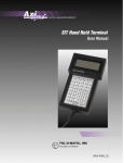
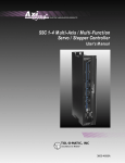
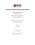
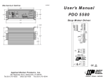
ELECTRIC LINEAR MOTION PRODUCTS
MSD Microstepping Motor Drive
USER'S MANUAL
TOL-O-MATIC, INC
Excellence in Motion®
3600-4053C
© Copyright 1998
Tol-O-Matic, Incorporated.
All rights reserved.
Axidyne and Tol-O-Matic
are registered trademarks of
Tol-O-Matic Incorporated.
1/2000
B A S I C
W I R I N G
C O N N E C T I O N
SPEED +
SPEED –
TACH +
TACH –
CW
WPR
CCW
DIR +
DIR –
STEP +
STEP –
EN+
EN–
FAULT+
FAULT–
S C H E M A T I C
F O R
DIR –
DIR +
STEP –
STEP +
T H E
M S D
STEP & DIRECTION
CONTROLLER
WITH THE MRS171 MOTOR
THE WIRING COLOR CODE IS AS FOLLOWS
A+ = WHT
A– = YLW
MSD
B– = BLU
B–
B+
A–
A+
GND
L2/N
L1
YLW
RED
ORG
BLK
GRN
WHT
BLK
B–
B+
A–
A+
X-AXIS
B+ = RED
MRS
MOTOR
Connection for Pulse and Direction Mode
i
Contents
Introduction
About this Manual.......................................................................................1
Safety Symbols........................................................................................1
Features........................................................................................................2
Modes of Operation ....................................................................................4
Getting Started.............................................................................................5
Connections
Connections and Adjustments...................................................................6
Connecting an Ac Line................................................................................7
Installing an Ac Line Cord.....................................................................8
Connecting the Motor.................................................................................9
Connecting Logic ......................................................................................10
Differential Logic .................................................................................11
Sinking Logic........................................................................................12
Sourcing Logic......................................................................................12
Setting up for Joystick Mode ................................................................13
Setting up for Oscillator Mode ............................................................15
Setting up for Analog Signal (using an Analog Signal) .....................17
Connecting Digital Inputs and Limit Switches .......................................19
Tach Output .........................................................................................19
Enable Input ........................................................................................19
Using the Fault Output .............................................................................20
Settings
Setting Phase Current ...............................................................................21
Current Setting Formula .....................................................................21
Current Setting Tables .........................................................................22
Special Features
Idle Current Reduction .............................................................................23
Microstepping ...........................................................................................23
Fault Protection .........................................................................................25
Temp .....................................................................................................25
Short .....................................................................................................25
Technical Specifications
Specifications ............................................................................................26
Dimensions................................................................................................28
Mounting Information
Mounting the MSD....................................................................................29
Use and Care ........................................................................................29
ii
C O N T E N T S
Recommended Motors
Motor Data and Dimensions ..............................................................30
Tol-O-Matic Catalog Motor Summary Data ......................................30
17 Frame Motor Dimensions Speed/Torque .......................................30
23 Frame Motor Dimensions...............................................................31
23 Frame Motor Speed/Torque Characteristics...................................31
34 Frame Motor Dimensions...............................................................32
34 Frame Motor Speed/Torque Characteristics...................................32
iii
C O N T E N T S
iv
Introduction
About This Manual
This manual provides the information necessary to configure and
install the Tol-O-Matic MSD Micro Stepping Drive for use with any
of the Tol-O-Matic MRS stepper motors, and with the Tol-O-Matic
SSC servo/stepper controller or other step and direction sources.
If you have difficulty configuring, installing, or programming
your system, please contact your local distributor for help, or
call Tol-O-Matic at 1-800-328-2174.
SAFETY SYMBOLS
The following symbols are used throughout this manual to alert the
user to potential safety hazards.
Caution! When this symbol appears, exercise care to avoid the
possibility of sustaining slight operator injury or equipment
damage.
WARNING! When this symbol appears, exercise extreme caution
to avoid an IMMEDIATE DANGER of sustaining severe operator
injury or irreparable equipment damage.
NOTE: Failure to comply with cautions, warnings and requirements
in this manual, may result in damage to equipment not covered
under Tol-O-Matic warranties.
1
I N T R O D U C T I O N
Features
The MSD Stepper Drive is a microstepping chopper drive with
integral power supply, packaged in a sheet metal enclosure with
heat sink.
DIR+
DIR–
SPEED+ STEP+
SPEED- STEP–
TACH+
EN+
TACH–
EN–
CW
FAULT+
WPR FAULT–
CCW
TEMP
POWER
• Digital oscillator provides smooth accel/decel ramps and
precise speed control.
SHORT
JOYSTICK
EXT SPEED
50% IDLE
CURRENT
(BASE = 0.5 A)
• Powerful microstepping amplifier provides high torque and
smooth, quiet motion.
0.2
0.4
0.8
1.6
2.0
HIGH SPEED
STEPS/REV
LOW SPEED
ACCEL
• Accepts a wide range of motors: NEMA sizes 14 - 42, 0.5 to 5.5
Amps peak/phase.
OSC BYPASS
SELF TEST
MSD
MicroStepping
MicroStepping
Motor
Motor Drive
Drive
MOTOR
B–
B+
A–
A+
• Easy to configure with on-board switches and potentiometers
for all settings.
• Automatic idle current reduction reduces motor and drive
heating, saves power.
90V pk
• Pluggable screw terminal connectors make wiring easy.
TOL-O-MATIC, INC.
Hamel, MN, USA
• Oscillator Mode operates from internal pots, external pots,
0 - 5V dc analog signal, or analog joystick.
AC
POWER
G
N
L
• Two speed ranges, can be selected “on the fly” by a digital
signal with automatic ramping between speeds.
• Inputs and outputs are optically isolated, differential
(sourcing or sinking). Speed & Enable 5 - 24V dc, Step &
Direction 5 - 12V dc.
• Tach Out signal allows easy measurement of speed.
• Enable input allows motor current to be shut off on command.
• Built-in 80 volt power supply (accepts 110 or 220 Vac power,
50-60 Hz).
• MOSFET pulse width modulation switching amplifiers (3 state).
continued
2
I N T R O D U C T I O N
• Microstepping pulse & direction model with 16 step/rev
settings from 200 (full step) through 50,800.
• Overtemp and overcurrent (short circuit) and surge
protection.
• Built-in self test for troubleshooting.
• CE and TUV compliant.
3
I N T R O D U C T I O N
Modes of Operation
The MSD has four modes of operation, selected by three dip switches.
OSC BYPASS
SELF TEST
5 6
Pulse & Direction Mode – the MSD
receives step pulses from an indexer
such as the SSC. Steps/revolution are
set by switches 1-4. This mode is the
same as earlier models of MSD.
Pulse & Direction Mode
JOYSTICK
1
OSC BYPASS
5 6
Joystick Mode – speed and direction
are determined by an external analog
voltage. STEP and DIR inputs can be
used for limit switches. SPEED input
selects speed range. LO SPEED and HI
SPEED pots adjust the 2 speed ranges.
SELF TEST
Oscillator Mode – speed can be
shooting. If the MSD isn’t responding to
step pulses, turn on the self test.
JOYSTICK
OSC BYPASS
5 6
Self Test Mode is used for trouble
Joystick Mode
1
controlled by on-board potentiometers
and/or by an external analog voltage.
STEP input starts and stops the motor.
DIR input controls direction of rotation.
SPEED input selects the speed range.
SELF TEST
Oscillator Mode
6
To activate the self test, slide switch #6
toward the TEST label. The drive will
SELF TEST
slowly rotate the motor, 1/2 revolution
forward, then 1/2 rev backward. The
pattern repeats until the switch is
Self Test Mode
moved away from the TEST label. The
MSD always uses half step mode during the self test, no matter how
the steps/rev switches are set. The self test ignores the STEP and
DIRECTION inputs while operating. The ENABLE input continues to
function normally.
4
I N T R O D U C T I O N
Getting Started
To use the MSD Microstepping Motor Drive, the following are
needed:
• a power cable (line cord)
• a compatible step motor
• a small flat blade screwdriver for tightening the connectors
For pulse & direction mode:
• a source of step pulses (usually an indexer is used)
For oscillator mode:
• an instrument for measuring motor speed (tachometer, freq. counter or
o-scope)
For joystick mode:
• an analog joystick
5
Connections
Connections and Adjustments
Refer to Figure 2 for important connection and adjustment points.
All mating connectors are included.
DIR+
DIR–
SPEED+ STEP+
SPEED- STEP–
TACH+
EN+
TACH–
EN–
CW
FAULT+
WPR FAULT–
CCW
Logic Connector
DIR
STEP
ENABLE
FAULT OUT
TEMP
POWER
SHORT
JOYSTICK
EXT SPEED
50% IDLE
CURRENT
(BASE = 0.5 A)
0.2
0.4
0.8
1.6
2.0
HIGH SPEED
STEPS/REV
LOW SPEED
ACCEL
LEDs
POWER
TEMP
SHORT
Switches
IDLE REDUCTION
PHASE CURRENT
OSC BYPASS
SELF TEST
MSD
MicroStepping
MicroStepping
Motor
Motor Drive
Drive
MOTOR
B–
B+
A–
A+
Switches
MICROSTEP
RESOLUTION
90V pk
TOL-O-MATIC, INC.
Hamel, MN, USA
AC
POWER
G
N
Connector
MOTOR
Connector
Ac POWER
L
Figure 2 - CONNECTION AND ADJUSTMENT POINTS
6
C O N N E C T I O N S
Connecting the Ac Line
110 Volts
The MSD is set for 110 Volt operation at the factory. Install a power
cord and plug it in. Before direct wiring the MSD to ac power,
consult a qualified electrician and observe all building and
electrical codes.
WARNING! Ac power can be dangerous. Use extreme caution in
installing the ac cord.
220 Volts
The MSD is set for 110 Volt operation at the factory. In order to use
220 Volts, a switch setting inside the case must be changed. This can
be done from the outside with a small screwdriver.
Caution! Do not open the MSD case. Do not attempt to change the
110/220 Volt switch setting until the power has been removed from
the drive for at least five minutes.
Before changing the 110/220 Volt switch setting, remove the motor
connector and the ac power connector from the drive. Set the drive
on the widest side, so that the heat sink fins are pointing upward.
Look through the opening in the case located directly above the
three position and four position green connectors (see Figure 3)
B–
B+
A–
A+
GND
N
L
B–
B+
A–
A+
GND
N
L
MOTOR
B–
B+
A–
A+
GND
L
N
TOL-O-MATIC, INC.
Hamel, MN
AC POWER
Unplug these connectors
fuse
switch in 110V position
fuse
switch in 220V position
Figure 3 - 200V SWITCH SETTINGS
continued
7
C O N N E C T I O N S
and observe two black objects. The one on the left is the fuse. The
black object to the right of the fuse is the 110/220 V switch. Figure 3
shows the two positions of the switch. To change from 110V to 220V,
carefully insert a screwdriver into the slot and push the switch to the
right.
INSTALLING AN AC LINE CORD
WARNING! Always use a three-wire power cord when working with
ac power. Failure to do so could result in damage to the MSD and/or
personal injury or death.
WARNING! Always disconnect the line cord from the source before
attaching it to the MSD.
Remove approximately 5 mm ( 3/16 inches) of insulation from each of
the three wires of the line cord. Depending on the source, the power
cord, may have black, white and green wires or brown/blue/green.
Connections
Refer to Figure 4.
Figure 4 - AC LINE CORD INSTALLATION
1. Connect the black or brown wire to the MSD “L” (line or “hot”
terminal of the ac power connector.
2. Connect the white or blue wire to neutral. That’s the “N” terminal.
3. Connect the green wire to the GND terminal. This connects the MSD
metal enclosure and dc power supply ground to earth ground.
8
C O N N E C T I O N S
Connecting the Motor
Caution! To avoid personal injury and/or damaging the MSD:
• Never connect the motor to the driver when the ac power is on.
• Never disconnect the motor while the ac power is on.
• Never connect motor leads to ground or to a power supply.
Tol-O-Matic catalog stepper motors are all four-lead, parallel
connected. Four-lead motors should be connected as shown in
Figure 5. See pages 25 and 26 for Tol-O-Matic recommended
motors.
A+
White
A+
4-lead
motor
A–
Black
4-lead
motor
A–
Yellow
Orange
Blue
Red
B+
Yellow
Red
B–
B+
MRS 171 FRAME MOTOR
B–
MRS 23 AND 34 FRAME MOTORS
Figure 5 - MOTOR CONNECTION
To reverse the rotation at the motor (rather than in programming),
reverse the + and - connections of one phase.
(Full Stepping)
DIR=1
cw
Step
0
1
2
3
4
A+
+
+
–
–
+
A–
–
+
+
–
B+
+
–
–
+
+
B–
+
+
–
–
DIR=0
ccw
(Step 2 is the Power Up State)
Figure 6 - STEP TABLE
9
C O N N E C T I O N S
Connecting Logic
The MSD drive contains optical isolation circuitry to prevent the
electrical noise inherent in switching amplifiers from interfering
with your circuits. A schematic diagram of the step input circuit is
shown in Figure 7. NOTE: DIRECTION and ENABLE circuits are the
same as STEP.
STEP+
680½
STEPFigure 7 - INPUT CIRCUIT
The logic signals can be sourcing, sinking or both (differential). The
input current will be about 1 mA per volt. Thus, if the logic signals
are 5 Volts, then logic low, or 0, for a given input, occurs when the +
and - signal pins have at least 4 Volts dc across them. In this state the
LED is conducting current. Logic high, or 1, occurs when the + and inputs are less than 1 V apart, or open.
STEP signals the driver to move the motor one step. The drive steps on
the falling edge of the pulse. The minimum width is 1 microsecond.
DIRECTION controls which way the motor will turn. (See the Figure
6 for details). The DIRECTION signal should be changed at least 1
microsecond before a step pulse is sent and held for at least 50 µsec
after the step pulse is sent. If the controller changes the state of the
direction input and sends a step pulse at the same instant, the
motor may take a step in the wrong direction.
ENABLE allows the user to turn off the current to the motor by
setting this signal to logic 0. The logic circuitry continues to operate,
so the drive “remembers” the step position even when the amplifiers
are disabled. However, the motor may move slightly when the
current is removed depending on the exact motor and load
characteristics. If there is no need to disable the amplifiers, it is
unnecessary to connect anything to the ENABLE input.
10
C O N N E C T I O N S
Setting Up for Pulse & Direction Mode
• Connect an indexer/controller to the Step and Direction inputs.
• Set the steps/rev.
• Set the OSC Bypass and Self Test Switches (page 3).
DIFFERENTIAL LOGIC
If the controller has STEP+, STEP-, DIR+ and DIR- outputs, (which
many indexers do), connect STEP+ to STEP+, STEP- to STEP- and so
forth, as shown in Figure 8.
Indexer
or
Controller
with
Differential
Outputs
DIR+
DIR+
DIR-
DIR-
STEP+
STEP+
STEP-
STEP-
ENABLE+
ENABLE+
ENABLE-
ENABLE-
MSD
Drive
= optional signal
Figure 8 - DIFFERENTIAL LOGIC CONNECTIONS
11
C O N N E C T I O N S
SINKING LOGIC
If the controller has STEP, DIR and +5V outputs connect STEP+ and
DIR+ to +5V, then connect STEP- to STEP. Connect DIR- to DIR as
shown in Figure 9. This is the connection to use for the Tol-O-Matic
SSC servo/stepper controller.
Indexer
or
Controller
with
Sinking
Outputs
+5V OUT
DIR+
DIR
DIRSTEP+
STEP
STEP-
MSD
Drive
ENABLE+
ENABLE-
ENABLE= optional signal
Figure 9 - SINKING LOGIC CONNECTIONS
SOURCING LOGIC
If the controller has STEP, DIR and GND (ground or common)
outputs, connect STEP- and DIR- to GND, then connect STEP+ to
STEP. Connect DIR+ to DIR as shown in Figure 10.
DIR
Indexer
or
Controller
with
Sourcing
Outputs
DIR+
DIR-
STEP
STEP+
STEP-
ENABLE
ENABLE+
GROUND
ENABLE= optional signal
Figure 10 - SOURCING LOGIC CONNECTIONS
12
MSD
Drive
C O N N E C T I O N S
If the Logic Voltage is not 5 to 12 Volts...
The MSD optical isolation circuits have built in resistors for 5 - 12
Volt logic. If the logic voltage is greater than 12 Volts but no more
than 24 Volts, add series resistors to the signal “+” pins (i.e. STEP+,
DIR+, etc.). Use 1/4 Watt, 1000 ohms.
Setting Up for Joystick Mode
In this mode, speed and direction are determined by the voltage
applied to the WPR (wiper) terminal. 2.5 Volts is “stopped” (no
speed). Increasing the WPR voltage toward 5 volts results in forward
motion: speed increases with voltage. Decreasing the WPR voltage
from 2.5 toward 0 results in reverse motion, with speed increasing as
voltage decreases. In joystick mode, the MSD operates at 12800
steps/rev.
The maximum speed is determined by two things: the state of the
SPEED input and the HI SPEED and LO SPEED trimpots. When the
SPEED input is ON, the speed range of the joystick can be adjusted
with the LO SPEED pot, up to 5 rev/sec (300 rpm). When the SPEED
input is OFF (or open), the joystick speed range is adjusted with the
HI SPEED pot, up to 25 rev/sec (1500 rpm). Turning the pots
clockwise increases the speed.
In joystick mode, limit switches can be connected to the MSP to
prevent motion outside of defined limits. The forward limit should
be connected to the STEP input and the reverse limit should be
connected to the DIR input. When the forward limit is ON, the
motor will not move forward (that is, when the joystick voltage is
between 2.5 and 5 Volts). When the reverse limit is ON, the motor
will not move when the joystick is in the 0 to 2.5 Volt range. If limits
are not needed, leave the STEP and DIR inputs unconnected.
13
C O N N E C T I O N S
STEP +
DIR +
SPEED +
fwd limit switch
STEP –
DIR –
rev limit switch
joystick “fire” button
MSD
+
5-12
Vdc
SUPPLY
–
SPEED –
CW
fwd
5k½
joystick
WPR
rev
speed (rev/sec)
CCW
25
20
15
10
5
0
-5
-10
-15
-20
-25
0
1
2
3
volts
5
volts
Speed vs Input Voltage
Joystick Mode, SPEED input off (open)
HI SPEED pot at maximum
14
4
C O N N E C T I O N S
Setting Up for Oscillator Mode
In oscillator mode, the MSD uses the direction set by the DIR input.
Off, or open, gives clockwise motion. Motor speed and the function
of the STEP input can be determined from the following table. In
oscillator mode, the MSD operates at 12800 steps/rev.
SPEED
input
switches
1& 2
ON
joystick
ext speed
ON
joystick
ext speed
OFF/open
joystick
ext speed
OFF/open
joystick
ext speed
speed set
by
LO SPEED
LO SPEED
HI SPEED
WPR input
trimmed by
when STEP
goes ON
when STEP
goes OFF
accel to speed
instant stop
accel to speed
instant stop
accel to speed
decel to stop
accel to speed
decel to stop
HI SPEED
There are two speed ranges in oscillator mode. One is the low speed
range, which is activated when the SPEED input is on. The low speed
can be set from 0 to 5 rev/sec (0 - 300 rpm) by adjusting the LO
SPEED pot. Turning the pot clockwise increases the speed.
The high speed setting is used when the SPEED input is off, or open.
If switch #2 is toward the words EXT SPEED, then the high speed is
proportional to the voltage applied to the WPR terminal, and is
trimmed by the HI SPEED pot. Connect an external 1K - 5K pot to
the WPR, CW and CCW terminals, or apply a 0 to 5 Volt analog signal
to the WPR terminal (ground the analog signal to the CCW pin). The
high speed range is 0 - 25 rev/sec (0 - 1500 rpm). Reduce the range
by turning down the HI SPEED pot. For example, if the motor is to
go 750 rpm when the external pot is on maximum, turn the HI
SPEED pot down about half way.
When switch #2 is away from the EXT SPEED label, the high speed is
set by the HI SPEED pot and the WPR input does nothing.
Never apply more than 5 Volts dc or less than 0 Volts to the WPR pin.
In joystick and oscillator modes, the accel/decel rate is set by the
ACCEL pot.
15
C O N N E C T I O N S
The range is 1 to 250 rev/sec/sec. Turning the pot clockwise makes
the motor start and stop faster, but if set too high the motor may run
out of torque and stall.
In nearly all cases, the accel/decel rate set is respected by the MSD.
For example, if the speed is switched while the motor is moving, the
drive will change speeds smoothly. When operating in EXT SPEED
mode and a sudden change is made in the voltage to the WPR
terminal, the drive accelerates (or decelerates) to the new speed
smoothly, according to the accel pot setting.
The only time the drive makes an instant change is when the SPEED
input is on and the STEP input goes off. That is done so that the
MSD can stop instantly (and exactly) from a low speed.
STEP +
DIR +
run/stop switch
(closed=run)
SPEED +
STEP –
direction switch
speed switch (closed=low speed)
cw
5k½
pot
DIR –
MSD
+
5-12
Vdc
SUPPLY
–
SPEED –
CW
WPR
ccw
CCW
Typical Wiring for Oscillator Mode Using External Speed Control Pot
16
C O N N E C T I O N S
Setting Up for Oscillator Mode (using an Analog Signal)
In oscillator mode, the MSD can rotate the motor at a speed
proportional to an analog voltage. The voltage must be applied to
the WPR terminal. The direction of rotation is controlled by the
digital DIR input and the motor can be stopped either by setting the
analog input voltage to 0 or by turning the digital STEP signal off.
To use the MSD in this mode, set switch #1 away
joystick
from the JOYSTICK label, and set switch #2 toward
ext speed
the EXT SPEED label.
The HI SPEED pot sets the maximum speed (the motor speed when
the analog signal is at 5 Volt DC). The range is 0 - 25 rev/sec. Wiring
diagrams and a plot of speed vs voltage are shown below.
STEP +
run/stop switch
(closed=run)
DIR +
STEP –
direction switch
DIR –
0 - 5V speed signal
WPR
signal return
CCW
MSD
+
5-12
Vdc
SUPPLY
–
Wiring for Speed Control by 0 - 5 Volt Analog Signal (with Dir Control)
STEP +
CW
0 - 5V speed signal
WPR
signal return
CCW
MSD
STEP –
Wiring for Speed Control by 0 - 5 Volt Analog Signal (Unidirectional)
17
C O N N E C T I O N S
speed (rev/sec)
25
20
15
10
5
0
0
1
2
3
4
5
Speed vs Input Voltage
EXT SPEED mode, HI SPEED pot at maximum
Connecting Digital Inputs and Limit Switches
The MSD contains optical isolation circuitry to prevent the electrical
noise inherent in switching amplifiers from interfering with your
circuits. This arranagement also allows a wide range of input
voltages to be used and allows the option of using sinking or
sourcing inputs.
A schematic diagram of the input circuit is shown on the next page.
A 5 - 12 Vdc power supply must be used to supply current to the
LEDs on the input side of the optoisolators. 24 Vdc is acceptable for
the SPEED and ENABLE inputs. The STEP and DIR inputs can be
operated at 24V if a 1000 ohm resistor is added to each input. Most
CMOS and open collector TTL devices are directly compatible with
this drive, as are typical PLC and proximity sensor outputs.
STEP+
R
STEP–
MSD Input Circuit
18
C O N N E C T I O N S
SINKING CIRCUITS (NPN)
If the output devices prefer to sink current, then connect the “+”
terminals to the positive power supply, and the “–” terminals to the
signals (i.e. STEP–, DIR–, etc.). If a TTL circuit is used to drive the
MSD, connect the “+” terminals to the 5 Volt bus. No ground
connection is needed. If a PLC or proximity sensor is used, an
external power supply is needed.
SOURCING CIRCUITS (PNP)
If the output devices can only source current (some PLC outputs are
this way), connect the “–” terminals to the ground of the dc power
supply that powers the output circuits. Then connect the signals to
the “+” terminals (STEP+, DIR+, etc.).
NOTE: We refer to an input as being ON when current is flowing
through the input. A signal is OFF when no current is flowing. An
input is OFF when COM and the input terminal are at the same
voltage, or when the input is left unconnected (open).
Tach Output
The Tach Out signal is provided for measuring the motor speed. It
generates 100 pulses per revolution, so if a frequency counter is
connected, the speed will read out in revs/second with two decimal
places.
Do not connect the Tach output to more than 24Vdc.
The current into the Tach+ terminal must not exceed 20 mA.
Enable Input
ENABLE allows the user to turn off the current to the motor by setting
this signal to logic 0. The logic circuitry continues to operate, so the
drive “remembers” the step position even when the amplifiers are
disabled. However, the motor may move slightly when the current is
removed depending on the exact motor and load characteristics. If
you have no need to disable the amplifiers, you don’t need to
connect anything to the ENABLE input.
19
C O N N E C T I O N S
Using the Fault Output
The MSD has a fault output to indicate if the drive has overheated or
if a short circuit has occurred at the motor outputs. The fault output
is optically isolated for noise immunity. This makes it more flexible
and more reliable, but also more difficult to set up. To connect to
5 Volt logic, consult Figure 11. Max current is 20 mA. For other
connections, consult the factory.
The photo transistor turns on when there is a fault. In the circuit
shown in Figure 11, the signal will be high (near 5 Volts) when there
is no fault. The signal will go low (0 Volts) if a fault occurs.
+5 Vdc
Resistor
10k½ 1/4W
MSD
FAULT+
1k½
TTL or CMOS input
FAULT–
Figure 11 - FAULT OUTPUT
20
Settings
Setting Phase Current
Before turning on the power supply the first time, set the driver for
the proper motor phase current. The rated current is printed on the
motor label. The current to be set on the MSD is the peak current,
not rms, so multiply the motor rating by 1.414 to get the maximum
setting.
Refer to page 23 of this manual for current limit settings of
Tol-O-Matic MRS series stepper motors. The MSD current is easy
to set. Use the simple formula for setting current. Or skip to the table
on the next page, find the current setting you want, and set the DIP
switches according to the picture.
Caution! Settings higher than recommended will cause motor to
overheat.
CURRENT SETTING FORMULA
Refer to Figure 12. Locate the bank of seven switches labeled
CURRENT on the front face of the driver. Six of the switches have a
value of current printed next to them, such as 0.1 and 1.6. Each
switch controls the amount of current, in amperes (A), that its label
indicates. There is always a base current of 0.5 A. To add to that, slide
the appropriate switches toward their labels
Example
0.4
5
0.8
6
1.6
7
2.0
8
CURRENT
(BASE=0.5A)
0.2
4
Suppose you want to set the driver
for 2.9 Amps per phase. You need
the 0.5 A base current plus another
2.0 and 0.4 A.
2.9 (TOTAL) = 0.5 (BASE) + 2.0 + 0.4.
Slide the 2.0 and 0.4 A switches
toward the labels as shown in
the figure.
Figure 12 - CURRENT SETTING EXAMPLE
Refer to Figures 13 and 14 for current settings.
21
S E T T I N G S
Current Setting Table
AMPS/
PHASE
4.5
AMPS/
PHASE
0.2
0.4
0.8
1.6
2.0
0.2
0.4
0.8
1.6
2.0
5.1
AMPS/
PHASE
5.3
AMPS/
PHASE
5.5
AMPS/
PHASE
Figure 13 - CURRENT SETTING (0.5 - 3.2 A/phase)
22
0.2
0.4
0.8
1.6
2.0
0.2
0.4
0.8
1.6
2.0
0.2
0.4
0.8
1.6
2.0
4 5 6 7 8
4.3
AMPS/
PHASE
0.2
0.4
0.8
1.6
2.0
4 5 6 7 8
AMPS/
PHASE
0.2
0.4
0.8
1.6
2.0
4.9
4 5 6 7 8
4.1
AMPS/
PHASE
0.2
0.4
0.8
1.6
2.0
4 5 6 7 8
AMPS/
PHASE
0.2
0.4
0.8
1.6
2.0
4.7
4 5 6 7 8
AMPS/
PHASE
0.2
0.4
0.8
1.6
2.0
3.9
4 5 6 7 8
3.1
AMPS/
PHASE
0.2
0.4
0.8
1.6
2.0
4 5 6 7 8
AMPS/
PHASE
0.2
0.4
0.8
1.6
2.0
3.7
4 5 6 7 8
2.9
AMPS/
PHASE
0.2
0.4
0.8
1.6
2.0
4 5 6 7 8
AMPS/
PHASE
0.2
0.4
0.8
1.6
2.0
3.5
4 5 6 7 8
2.7
AMPS/
PHASE
0.2
0.4
0.8
1.6
2.0
4 5 6 7 8
AMPS/
PHASE
0.2
0.4
0.8
1.6
2.0
3.3
4 5 6 7 8
2.5
4 5 6 7 8
AMPS/
PHASE
0.2
0.4
0.8
1.6
2.0
AMPS/
PHASE
0.2
0.4
0.8
1.6
2.0
4 5 6 7 8
1.7
2.3
4 5 6 7 8
AMPS/
PHASE
0.2
0.4
0.8
1.6
2.0
AMPS/
PHASE
0.2
0.4
0.8
1.6
2.0
4 5 6 7 8
1.5
2.1
4 5 6 7 8
AMPS/
PHASE
0.2
0.4
0.8
1.6
2.0
AMPS/
PHASE
0.2
0.4
0.8
1.6
2.0
4 5 6 7 8
1.3
1.9
4 5 6 7 8
AMPS/
PHASE
0.2
0.4
0.8
1.6
2.0
4 5 6 7 8
1.1
4 5 6 7 8
AMPS/
PHASE
0.2
0.4
0.8
1.6
2.0
4 5 6 7 8
0.9
4 5 6 7 8
AMPS/
PHASE
0.2
0.4
0.8
1.6
2.0
4 5 6 7 8
0.7
4 5 6 7 8
AMPS/
PHASE
0.2
0.4
0.8
1.6
2.0
4 5 6 7 8
0.5
S E T T I N G S
Idle Current Reduction
The MSD drive is equipped with a feature that automatically reduces
the motor current by 50% anytime the motor is not moving. This
reduces drive heating by approximately 50% and lowers motor
heating by 75%. This feature can be disabled if desired so that full
current is maintained at all times. This is useful when a high holding
torque is required. To minimize motor and drive heating it is
strongly recommended that you use the idle current reduction
feature unless your application strictly forbids it. Idle current
reduction is enabled by sliding CURRENT switch #1 toward the 50%
IDLE label, as shown in Figure 15. Sliding the switch away from the
50% IDLE label disables the reduction feature.
Idle Current Reduction
Selected
50% IDLE
1
No Current Reduction
50% IDLE
1
Figure 15 - IDLE CURRENT REDUCTION
Microstepping
Most step motor drives offer a choice between full step and half step
resolutions. In full step mode, both motor phases are used all the
time. Half stepping divides each step into two smaller steps by
alternating between both phases on and one phase on.
Microstepping drives like the MSD precisely control the amount of
current in each phase at each step position as a means of
electronically subdividing the steps even further. The MSD offers a
choice of full and half step as well as 14 other step resolutions. The
highest setting divides each full step into 254 microsteps, providing
50,800 steps per revolution when using a 1.8o motor.
In addition to providing precise positioning and smooth motion,
microstep drives can be used for motion conversion between
different units. The 25,400 step/rev setting is provided as a means of
converting motion from metric to English. (There are 25.4 mm in an
inch.) Other settings provide step angles that are decimal degrees
continued
23
S E T T I N G S
(36,000 steps/rev makes the motor take 0.01o steps.) Some settings
are used with lead screws. When the drive is set to 2000 steps/rev
and used with a 5 pitch lead screw, you get .0001 inches/step.
1 2 3 4
1 2 3 4
1 2 3 4
1 2 3 4
50800
STEPS/REV
(1/254)
1 2 3 4
STEPS/REV
(1/250)
1 2 3 4
50000
1 2 3 4
36000
STEPS/REV
(.01¡)
1 2 3 4
25600
STEPS/REV
(1/128)
MICROSTEP
RESOLUTION
STEPS/REV
(1/127)
MICROSTEP
RESOLUTION
25400
MICROSTEP
RESOLUTION
25000
STEPS/REV
(1/125)
MICROSTEP
RESOLUTION
STEPS/REV
(1 arc min)
MICROSTEP
RESOLUTION
21600
MICROSTEP
RESOLUTION
1 2 3 4
STEPS/REV
(1/100)
MICROSTEP
RESOLUTION
1 2 3 4
20000
MICROSTEP
RESOLUTION
1 2 3 4
18000
STEPS/REV
(.02¡)
1 2 3 4
STEPS/REV
(1/64)
1 2 3 4
12800
1 2 3 4
10000
STEPS/REV
(1/50)
1 2 3 4
5000
STEPS/REV
(1/25)
1 2 3 4
STEPS/REV
(1/10)
MICROSTEP
RESOLUTION
2000
MICROSTEP
RESOLUTION
1000
STEPS/REV
(1/5)
MICROSTEP
RESOLUTION
STEPS/REV
(HALF)
MICROSTEP
RESOLUTION
400
MICROSTEP
RESOLUTION
STEPS/REV
(FULL)
MICROSTEP
RESOLUTION
200
MICROSTEP
RESOLUTION
These resolutions are for the motor
only. Actuator performance may not
correspond at high microstepping
rates due to system compliance
and friction.
MICROSTEP
RESOLUTION
NOTE:
Figure 16 - SELECTING MICROSTEP RESOLUTION
24
Special Features
Fault Protection
The MSD provides protection against motor short circuits and
excessive drive temperature.
TEMP
If the TEMP light is on the MSD has detected a thermal problem and
shut down the amplifiers. The first thing to do is to unplug the drive
from the power source. Next, carefully touch the heat sink. If it is
very hot, the drive has probably overheated. Usually this means
more air flow is needed around the drive.
SHORT
If the SHORT light is on the MSD has detected a short circuit and has
shut down the amplifiers. Unplug the drive from the power source.
Check the motor wiring carefully. Make sure that the connections to
the drive are secure and that any unused motor leads are insulated
from the drive, power supply and each other. Check the motor leads
for shorts between phases or to ground.
25
Technical Specifications
Specifications
Amplifiers
Dual, MOSFET H-bridge, 3 state, pulse width modulated switching
at 20 kHz. 0.5 - 5.5 Amps/phase peak output current, switch
selectable in 0.1 increments. 400 Watts maximum output power.
Overcurrent and overtemperature protection. Automatic idle
current reduction (defeatable), reduces current to 50% of setting
after one second.
Power Supply
Linear, toroidal transformer based for high reliability and low noise.
110 or 220 Vac input, switch selectable, 50-60 Hz. 400 W max., .
internally fused with a 2.5A 250Vac fuse, Dc voltage at nominal line
voltage: 75 Vdc full load, 90 Vdc no load.
Inputs
Speed, Enable: optically isolated, differential 5 - 24V dc logic, 2200
ohms internal resistor.
Step, Direction: optically isolated, differential 5 - 12V dc logic, 680
ohms internal resistance. (24V dc with external 1000 ohm resistors.)
Wiper: 0 - 5 V dc analog signal. Max recommended pot/joystick
impedance: 1K - 5K ohms. Joystick dead zone: ±80 mV.
Potentiometer/analog signal dead zone: 40 mV.
In pulse & direction mode, motor steps on falling edge of step input.
0.25 µsec minimum pulse, 2 MHz max step rate. 1 µsec minimum set
up time, 50µs minimum hold time for direction signal.
Outputs
Tach & Fault: Optically isolated, uncommitted (open collector, open
emitter) photo transistors. 30V, 20 mA max. Tach output is 100 pulses
per motor revolution, 50% duty cycle (square wave).
Microstepping
Oscillator/joystick modes: 1/64 step (12,800 s/r) with 1.8° motor.
Pulse & Direction mode: 16 switch selectable resolutions: 200, 400,
1000, 2000, 5000, 10000, 12800, 18000, 20000, 21600, 25000, 25400,
25600, 36000, 50000, 50800 steps/rev.
Self test: 1/2 step.
26
T E C H N I C A L
S P E C I F I C A T I O N S
Oscillator Mode Speed Ranges
LO speed range: 0 - 5 rev/sec
HI speed range: 0 - 25 rev/sec
Accel/decel range: 1 to 250 rev/sec/sec
Physical
Constructed with black anodized aluminum heat sink and heavy
gauge steel housing. 3 x 5.3 x 8 inches overall. 7.8 lbs. 70°C max. heat
sink temperature. Power, overtemp and overcurrent LEDs. Mounting
brackets and switch cover included.
Connectors
European style, pluggable screw terminal blocks. Motor: 4 position.
Signal input/output: 8 position. Ac Input: 3 position.
27
DIR+
DIR–
SPEED+
STEP+
SPEED- STEP–
TACH+
EN+
TACH–
EN–
CW
FAULT+
WPR FAULT–
CCW
POWER
0.2
0.4
0.8
1.6
2.0
JOYSTICK
EXT SPEED
50% IDLE
CURRENT
(BASE = 0.5 A)
HIGH SPEED
OSC BYPASS
SELF TEST
ACCEL
LOW SPEED
MSD
B–
B+
A–
A+
MicroStepping
MicroStepping
Motor
Motor Drive
Drive
MOTOR
90V pk
TOL-O-MATIC, INC.
Hamel, MN, USA
G
L
N
TEMP
SHORT
STEPS/REV
28
0.25"
2.15"
5.45 "
5.30 "
2.02 "
3.00 "
1.25 "
AC
POWER
3.07 "
S P E C I F I C A T I O N S
T E C H N I C A L
Dimensions
8.00 "
8.97 "
9.25 "
0.06"
Mounting Information
Mounting the MSD
The MSD can be mounted on the wide or the narrow side of the
case. Bolt brackets and screws from the accessory bag onto the MSD.
If mounting on the narrow side, first remove one of the screws from
the heat sink, then put it back with the bracket in place, as shown in
Figure 17.
Bracket position for
wide side mounting.
Place brackets on
top and bottom of
drive.
Bracket
position
for narrow
side
mounting.
Place
brackets
on top
and
bottom of
drive.
This screw is already
in the drive.
Figure 17 - MOUNTING BRACKETS
USE AND CARE
• Never use the MSD in a space where there is no air flow or where the
ambient temperature exceeds 50°C (12°F).
• Never block the fins of the heat sink or the vent holes.
• Never put the drive where it can get wet.
• Never allow metal particles near the drive.
29
Recommended Motors
Motor Data and Dimensions
Tol-O-Matic catalog motor current settings (Figure 18).
MOTOR
WINDING
CONNECTION
MAX. PERMISSABLE DRIVE
CURRENT SETTING
AMPS (PEAK)
ROTOR
INERTIA
(oz-in 2 )
WEIGHT
(lbs)
MRS171
parallel
1.0
0.17
0.66
MRS231
parallel
2.20
0.66
1.5
MRS232
parallel
3.60
1.39
2.5
MRS341
parallel
5.50
3.21
3.2
MRS342
parallel
5.50
6.56
5.3
MRS343
parallel
5.50
9.66
7.6
Tol-O-Matic 17 frame motor dimensions (Figure 19).
White
Yellow
Red
Blue
1.69
A+
AB+
B-
[42.93]
.079
[2.01]
©.197
©.197
[5.00]
[5.00]
©.867
MRS171
1.66
1.220
[42.16]
[30.99]
3600-6129
[22.02]
3.1 In/LB
.433
.217
[11.00]
Torque (oz.-in.)
[5.51]
2.126
1.66
[54.00]
[42.16]
.28
35
.24
30
.21
25
.17
.14
20
MR
S2137
1
.10
10
.07
5
.03
0
30
.787
[19.99]
40
15
4
8
1.220
[30.99]
12 16 20 24 28
Revs Per Second
32
36
40
17 frame motor speed/torque
characteristics (Figure 20).
R E C O M M E N D E D
M O T O R S
Tol-O-Matic 23 frame motor dimensions (Figure 21).
Motor
Model
L
Max.
2.06
MRS231 52.4
3.10
MRS232 78.8
Black
Orange
Red
Yellow
6&5
1&2
8&7
3&4
Bipolar
parallel
A+
AB+
B-
23 frame motor speed/torque characteristics (Figure 22).
200.0
180.0
Torque (oz•in)
160.0
MRS232
140.0
120.0
100.0
80.0
60.0
MRS231
40.0
20.0
0.0
0
4
8
12
16
20
24
28
32
36
40
Revs per Second
31
R E C O M M E N D E D
M O T O R S
Tol-O-Matic 34 frame motor dimensions (Figure 23).
Motor
Model
L
Max.
2.58
MRS341 65.54
3.76
MRS342 95.51
3.76
MRS343 95.51
A+
AB+
B-
Black
Orange
Red
Yellow
PLUS GREEN / YELLOW GROUND
34 frame motor speed/torque characteristics (Figure 24).
600.0
Torque (oz•in)
500.0
MRS343
400.0
MRS342
300.0
200.0
MRS341
100.0
0.0
0
4
8
12
16
20
24
Revs per Second
32
28
32
36
40
Notes:
TOL-O-MATIC, INC.
3800 County Road 116
Hamel, MN 55340
763.478.8000 Telephone
763.478.8080 Fax
http://www.tolomatic.com