1
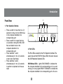
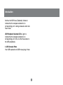
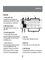
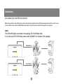
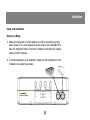
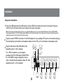
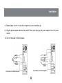
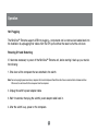
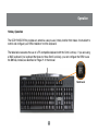
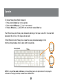
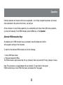
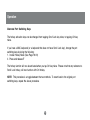
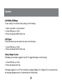
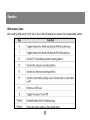
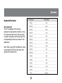
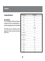
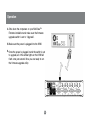
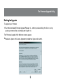
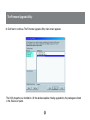
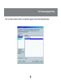
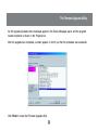
MiniView™ Extreme
Multimedia KVMP Switch
User Manual (GCS1732 / GCS1734)
®
Thank you for purchasing one of the most feature rich KVM and peripheral sharing switch on the market.
IOGEAR’s MiniView™ Extreme Multimedia KVMP Switch brings extra value to conventional KVM switches
by offering USB peripheral sharing capabilities, audio and microphone support, and multi-platform support
for Mac, Sun, USB and PS/2. You can save money and space by eliminating the need for multiple monitors,
keyboards, mice, and peripheral devices such as printers, scanners, zip drives, and more. Up to 127
different USB devices can be daisy chained from this KVMP switch. Sharing speakers and a microphone
also offers extra value and convenience for the users.
USB and KVM technology together makes cross-platform management easy. A single USB console can
control a PC and a Mac, or even a Sun workstation, and share peripherals and audio devices between the
computers. Any USB-enabled computers, using any USB-compatible operating system, can benefit from
the efficiency, expense reduction and convenience of IOGEAR’s Miniview Extreme KVMP switch.
We hope you enjoy using your Miniview™ Extreme Multimedia KVMP switch, yet another first-rate
connectivity solution from IOGEAR.
©2005 IOGEAR. All Rights Reserved. PKG-M0085C
IOGEAR, the IOGEAR logo, MiniView, VSE are trademarks or registered trademarks of IOGEAR, Inc. Microsoft and Windows are registered trademarks of
Microsoft Corporation. IBM is a registered trademark of International Business Machines, Inc. Macintosh, G3/G4 and iMac are registered trademarks of
Apple Computer, Inc. IOGEAR makes no warranty of any kind with regards to the information presented in this document. All information furnished here is
for informational purposes only and is subject to change without notice. IOGEAR, Inc. assumes no responsibility for any inaccuracies or errors that may
appear in this document.
Table of Contents
Package Contents
Overview
Features
Requirements
Introduction
Installation
Operation
Keyboard Emulation for Mac and SUN
The Firmware Upgrade Utility
Appendix
Specification
Technical Support
Radio & TV Interference Statement
Limited Warranty
○
○
○
○
○
○
○
○
○
○
○
○
○
○
○
○
○
○
○
○
○
○
○
○
○
○
○
○
○
○
○
○
○
○
○
○
○
○
○
○
○
○
○
○
○
○
○
○
○
○
○
○
○
○
○
○
○
○
○
○
○
○
○
○
○
○
○
○
○
○
○
○
○
○
○
○
○
○
○
○
○
○
○
○
○
○
○
○
○
○
○
○
○
○
1
○
○
○
○
○
○
○
○
○
○
○
○
○
○
○
○
○
○
○
○
○
○
○
○
○
○
○
○
○
○
○
○
○
○
○
○
○
○
○
○
○
○
○
○
○
○
○
○
○
○
○
○
○
○
○
○
○
○
○
○
○
○
○
○
○
○
○
○
○
○
○
○
○
○
○
○
○
○
○
○
○
○
○
○
○
○
○
○
○
○
○
○
○
○
○
○
○
○
○
○
○
○
○
○
○
○
○
○
○
○
○
○
○
○
○
○
○
○
○
○
○
○
○
○
○
○
○
○
○
○
○
○
○
○
○
○
○
○
○
○
○
○
○
○
○
○
○
○
○
○
○
○
○
○
○
○
○
○
○
○
○
○
○
○
○
○
○
○
○
○
○
○
○
○
○
○
○
○
○
○
○
○
○
○
○
○
○
○
○
○
○
○
○
○
○
○
○
○
○
○
○
○
○
○
○
○
○
○
○
○
○
○
○
○
○
○
○
○
○
○
○
○
○
○
○
○
○
○
○
○
○
○
○
○
○
○
○
○
○
○
○
○
○
○
○
○
○
○
○
○
○
○
○
○
○
○
○
○
○
○
○
○
○
○
○
○
○
○
○
○
○
○
○
○
○
○
○
○
○
○
○
02
03
04
05
06
10
13
24
26
34
35
37
38
39
Package Contents
This package contains:
1
2
1
1
1
1
1
MiniView™ Extreme Multimedia KVMP Switch (GCS1732 or GCS1734)
or 4 bonded KVM Cables (2 for GCS1732, 4 for GCS1734)
Power Adapter
Firmware Upgrade Cable
User Manual
Quick Start Guide
Warranty/Registration Card
If any items are damaged or missing please contact your dealer.
2
Overview
Overview
IOGEAR’s new MiniView™ Extreme Multimedia KVMP Switch brings extra value to conventional KVM
switches by offering USB peripheral sharing capabilities, audio and microphone support, and multi-platform
support for Mac, Sun, USB and PS/2. You can save money and space by eliminating the need for multiple
monitors, keyboards, mice, and peripheral devices such as printers, scanners, zip drives, and more. Up to
127 different USB devices can be daisy chained from this KVMP switch. Sharing speakers and a microphone
also offers extra value and convenience for the users.
USB and KVM technology together makes cross-platform management easy. A single USB console can
control a PC and a Mac, or even a Sun workstation, and share peripherals and audio devices between the
computers. Any USB-enabled computers, using any USB-compatible operating system, can benefit from the
efficiency, expense reduction and convenience of IOGEAR’s Miniview™ Extreme Multimedia KVMP switch.
3
Features
Features
• Multi functional switch allows multiple USB or PS/2 (additional cables needed) computers to share one USB
console and two USB peripheral devices such as printers and scanners, as well as speakers and a microphone
• User can conveniently switch USB peripheral devices from one computer to another using Hot Keys
• USB peripheral devices and USB consoles can be switched asynchronously from one computer to
another using Hot Keys
• Fully compliant with USB 1.1 specifications and delivers a 12 Mbps data transmission rate
• Complete keyboard and mouse emulation for error free booting
• Support special keys on Mac and Sun keyboard
• Allows PC keyboards to simulate Mac and Sun special keys through Hotkeys
• Features AutoScan mode to monitor all computers
• LED display for easy status monitoring
• Superior video quality - supports resolutions up to 2048 x 1536
• Extra convenience offered through sharing of speakers and microphone
• Easy installation: no software required, hot swappable
• Compact design for easy placement
4
Requirements
System Requirements
•
•
•
•
•
Computers with USB or PS/2 connections (additional cables needed for PS/2 computers)
Windows 98, 98SE, ME, 2000, XP
Mac OS 8.6 or greater
Sun Solaris work station
Linux, UNIX and other USB supported systems*
*Additional drivers and support may be needed
Audio
Only 2-piece, powered speaker system is supported
Accessories
• PS/2 KVM Cable (G2L5302P)
• USB KVM Console Extender (GCE700)
5
Introduction
Front View
1
1. Port Selection Buttons
•
•
•
•
Press a switch for less than two (2)
seconds to bring only the KVM focus
to the computer attached to its
corresponding port
Press a switch for longer than two
(2) seconds to bring the KVM, USB
hub, and Audio focus to the
computer attached to its
corresponding port
Press switches 1 and 2
simultaneously for two (2) seconds
to start Auto Scan Mode.
Press switches 3 and 4
simultaneously for two (2) seconds
to perform a keyboard and mouse
reset
2
3
2. Port LEDs
The Port LEDs are built into the Port Selection Switches. The
upper ones are the KVM Port Status LEDs; the lower ones are
the USB Peripheral Selected LEDs:
KVM Status LEDs: Lights DIM ORANGE to indicate that
the computer attached to the corresponding port is up and
running (On Line); lights BRIGHT ORANGE to indicate that
the computer attached to its corresponding port is the one
6
Introduction
that has the KVM focus (Selected); flashes to
indicate that the computer attached to its
corresponding port is being accessed under Auto
Scan mode.
USB Peripheral Selected LEDs: Lights to
indicate that the computer attached to its
corresponding port is the one that has access to
the USB peripherals.
3. USB Console Ports
Your USB keyboard and USB mouse plug in here.
7
Introduction
Back View
2
1
3
6
1. Console Audio Jacks
The cables from your microphone and
speakers plug in here. Each jack is marked
with an appropriate icon to indicate itself.
2. USB Peripheral Section
USB peripherals (printers, scanners, etc.)
plug in here.
3. Firmware Upgrade Section
• Firmware Upgrade Recovery Switch:
During normal operation and while performing
a firmware upgrade, this switch should be in
the NORMAL position.
• Firmware Upgrade Port:
The Firmware Upgrade Cable that transfers
the firmware upgrade data from the
administrator’s computer to the GCS1732 /
GCS1734 plugs into this RJ-11 connector.
See Pg. 25 for firmware upgrading details.
4
5
6
4. Power Jack
The power adapter cable plugs into this jack.
5. Monitor Port
The video cable from your monitor plugs in here.
6. CPU Port Section
The cables that link the switch to your computers plug
in here. Each CPU port is comprised of a microphone
8
Introduction
jack, speaker jack, and KVM data connector.
Note: The shape of these 15-pin KVM data connectors has been specifically modified so that only KVM cables designed to work with this switch can plug
in (see the Cables section for details). Do NOT attempt to use ordinary 15 pin VGA connector cables to link these ports to the computers
Cable
The USB KVM Cables are included in the package. DB-15 KVM data cable.
If you need some PS/2 KVM cable, please order G2L5302P (not included in this package).
USB KVM Cable
PS/2 KVM Cable
9
Installation
Setup and Installation
Before you Begin
1. Make sure that power to all the devices you will be connecting up have
been turned off. You must unplug the power cords of any computers that
have the Keyboard Power On function. Otherwise, the switch will receive
power from the computer.
2. To prevent damage to your installation make sure that all devices on the
installation are properly grounded.
10
Installation
Setup and Installation
1. Plug your USB keyboard and USB mouse into the USB Ports located on the unit’s front panel. Plug your
monitor into the Console monitor port located on the unit’s rear panel.
Note: For computers with older operating systems, such as Windows ME or prior, you may have to load the USB driver. Keep your OS CD ROM
handy during installation. If it is the first time you load the USB driver on this type of computers, there is a big chance that you may need to keep the old
keyboard and mouse on that computer until the driver is loaded.
2.
Plug the custom SPDB15 connector of the KVM cables into any available CPU ports on the switch and plug
the accompanying microphone and speaker cables into the CPU port’s microphone and speaker jacks.
3.
Plug the other end of the KVM cable to the
respective ports on the computer.
For a PS/2 connection, you will need to
purchase the PS/2 KVM cable (IOGEAR Part
No. G2L5302P), plug the keyboard, mouse,
video, microphone and speaker cables into their
respective ports on the computer.
11
Installation
4. Repeat steps 3 and 4 for any other computers you are connecting up.
5. Plug the power adapter cable into the switch’s Power Jack, then plug the power adapter into an AC power
source.
6. Turn on the power to the computers.
(Connection for PS/2 Computers)
(Connection for USB Computers)
12
Operation
Hot Plugging
The MiniView™ Extreme supports USB hot plugging – components can be removed and added back into
the installation by unplugging their cables from the CPU ports without the need to shut the unit down.
Powering Off and Restarting
If it becomes necessary to power off the MiniView™ Extreme unit, before starting it back up you must do
the following:
1. Shut down all the computers that are attached to the switch.
Note: You must unplug the power cords of any computers that have the Keyboard Power On function that are connected to the shut down switches.
Otherwise, the switches will still receive power from the computers.
2. Unplug the switch’s power adapter cable.
3. Wait 10 seconds, then plug the switch’s power adapter cable back in.
4. After the switch is up, power on the computers.
13
Operation
Hotkey Operation
The GCS1732/GCS1734 provides an extensive, easy-to-use, hotkey function that makes it convenient to
control and configure your KVM installation from the keyboard.
The table below assumes the use of a PC-compatible keyboard with the Scroll Lock key. If you are using
a MAC keyboard (or a keyboard that does not have Scroll Lock key), you can configure the KVM to use
the Ctrl key instead, as described on Page 21 of the manual
Scroll Lock
14
Operation
Port Switching
All port switches begin with tapping the Scroll Lock key twice:
[Scroll Lock], [Scroll Lock] + any of the actions on the table below
Cycling Through the Ports
15
Operation
Going Directly to a Port
Note: The n stands for the computer’s Port
ID number (1, 2, 3, or 4). Replace the n
with the appropriate Port ID when entering
hotkey combinations.
16
Operation
Auto Scanning:
The GCS1732 / GCS1734’s Auto Scan feature automatically cycles the KVM focus through the computer
ports at regular intervals. This allows you to monitor the computer activity without having to take the trouble
of switching from port to port manually. See the table below for details.
Note: The n stands for the number of seconds that the GCS1732 / GCS1734 should dwell on a port before
moving on to the next. Replace the n with a number between 1 and 99 when entering this hotkey
combination.
17
Operation
Hotkey Setting Mode (HSM)
OSD Operation
For all Hotkey operations, you must use the number keypad on the right side of your keyboard.
To
1.
2.
3.
Invoke Hotkey Mode (PC-Compatible Keyboard):
Press and hold Num Lock key for two seconds
Press and hold Minus key [ – ] for one second
Release Minus key [ – ] and within one second also release Num Lock key
The KVM will now enter Hotkey mode, and the Caps Lock and Scroll Lock LEDs flash in succession to
indicate this. On PC-Compatible keyboards this LED is usually located on top right-hand corner.
If the KVM did not enter Hotkey mode, repeat the above procedure keeping in mind that this entire
procedure must be done within five seconds.
PC keyboard
Num Lock
Minus
18
Operation
To
1.
2.
3.
Invoke Hotkey Mode (MAC Keyboard):
Press and hold Clear key for two seconds
Press and hold Minus key [ – ] key for one second
Release Minus key [ – ] and within one second also release Clear key
The KVM will now enter Hotkey mode; indicated by blinking of the Caps Locks LED. On some MAC
keyboards, this LED is on the Caps Lock key itself.
If the KVM did not enter Hotkey mode, repeat the above procedure keeping in mind
that this entire procedure must be done within five seconds.
Mac keyboard
Clear
Minus
NOTE: If using the Num Lock and Minus key to invoke Hotkey mode is not optimal, refer to the next page for
instructions on changing the hotkey invocation keys to Ctrl and F12.
19
Operation
Ordinary keyboard and mouse functions are suspended - only Hotkey compliant keystrokes and mouse
clicks (described in the sections that follow), can be input.
At the conclusion of some hotkey operations, you automatically exit hotkey mode. With some operations,
you must exit manually. To exit HSM manually, press the Esc key, or the Spacebar.
Alternate HSM Invocation Keys
An alternate set of HSM invocation keys is provided in case the default set conflicts
with programs running on the computers.
To switch to the alternate HSM invocation set, do the following:
1. Invoke HSM (see above)
2. Press and release the H key
The HSM invocation keys become the Ctrl key (instead of Num Lock) and the F12 key (instead of minus).
Note: This procedure is a toggle between the two methods. To revert back to the original
HSM invocation keys, invoke HSM, then press and release the H key again.
20
Operation
Alternate Port Switching Keys
The hotkey activation keys can be changed from tapping Scroll Lock key twice, to tapping Ctrl key
twice.
If you have a MAC keyboard (or a keyboard that does not have Scroll Lock key), change the port
switching keys by doing the following:
1. Invoke Hotkey Mode (See Page 18-19)
2. Press and release T
The hotkey function will now be activated when you tap Ctrl key twice. Please note that any reference to
Scroll Lock hotkey, will now function with Ctrl hotkey.
NOTE: This procedure is a toggle between the two methods. To revert back to the original port
switching keys, repeat the above procedure.
21
Operation
Keyboard Operating Platform
The GCS1732 / GCS1734’s default port configuration is for a PC Compatible keyboard operating
platform.
If your requirements call for different port settings (you have a Mac or Sun attached to a port, e.g.), you
can change a port’s keyboard operating platform configuration as follows:
1. Bring the KVM focus to the port you want to set.
2. Invoke Hotkey mode
3. Press and release the appropriate Function key (see table).
* The first time that the Sun system runs from a port, you must configure its port for the Sun keyboard
operating platform before you turn the system on, or else the Sun system will not start.
22
Operation
List Hotkey Settings:
To see a listing of the current hotkey settings, do the following:
1. Open a text editor or word processor
2. Invoke HSM (see p. 18-19)
3. Press and release the F4 function key
USB Reset
If the USB loses focus and needs to be reset, do the following:
1. Invoke HSM (see p. 18-19).
2. Press and release the F5 function key.
Hotkey Beeper Control
The Beeper can be hotkey toggled On and Off. To toggle the Beeper, do the following:
1. Invoke HSM (see p. 18-19).
2. Press and release the B key.
The Beeper toggles On or Off. The Command Line displays Beeper On or Beeper Off for one second; then
the message disappears and you automatically exit Hotkey Mode.
23
Operation
Disable Port Switching Keys
To disable the Port Switching Keys ([Scroll Lock] [Scroll Lock] / [Ctrl] [Ctrl]), do the following:
1. Invoke HSM (see p. 17).
2. Press [X] [Enter].
Note: This procedure is a toggle. To enable the Port Switching keys repeat steps 1 and 2.
Restore Default Settings
To reset the GCS1732 / GCS1734 to its default hotkey settings, do the following:
1. Invoke HSM (see p. 17).
2. Press [R] [Enter].
All hotkey settings return to the factory default settings.
24
Operation
HSM Summary Table:
After invoking HSM (see p.18-19), key in one of the following keys to perform the corresponding function:
25
Operation
Keyboard Emulation:
Sun Keyboard
The PC compatible (101/104 key)
keyboard can emulate the functions of the
Sun keyboard when the Control key [Ctrl]
is used in conjunction with other keys. The
corresponding functions are shown in the
table below.
Note: When using [Ctrl] combinatons, press
and release the Ctrl key, then press and
release the activation key.
26
Operation
Keyboard Emulation:
Mac Keyboard
The PC compatible (101/104 key) keyboard can
emulate the functions of the Mac keyboard. The
emulation mappings are listed in the table below.
Note: When using key combinatons, press and
release the first key, then press and release the
second one.
27
The Firmware Upgrade Utility
The Windows-based Firmware Upgrade Utility (FWUpgrade.exe) provides a smooth, automated process
for upgrading the KVM switch’s firmware.
The Utility comes as part of a Firmware Upgrade Package that is specific for each device. New firmware
upgrade packages are posted on our web site as new firmware revisions become available. Check the
web site regularly to find the latest packages and information relating to them:
http://www.iogear.com
Before You Begin
To prepare for the firmware upgrade, do the following:
1. From a computer that is not part of your KVM installation, go to the IOGEAR support site and select
the product part number (GCS1732 or GCS1734) to get a list of available Firmware Upgrade
Packages.
2. Choose the Firmware Upgrade Package you want to install (usually the most recent), and download
it to your computer.
3. Use the Firmware Upgrade Cable provided with this unit, to connect a COM port on your computer
to the Firmware Upgrade Port of your switch.
28
Operation
4. Shut down the computers on your MiniView™
Extreme installation and make sure the firmware
upgrade switch is set to “Upgrade”.
5. Make sure the power is plugged into the KVM.
6. Once the power is plugged in and the switch is set
to upgrade, all of the amber lights on the KVM will
flash once per second. Now you are ready to run
the firmware upgrade utility.
29
The Firmware Upgrade Utility
Starting the Upgrade
To upgrade your firmware:
1. Run the downloaded Firmware Upgrade Package file - either by double-clicking the file icon, or by
opening a command line and entering the full path to it.
The Firmware Upgrade Utility Welcome screen appears:
2. Read and Agree to the License Agreement (enable the I Agree radio button).
30
The Firmware Upgrade Utility
3. Click Next to continue. The Firmware Upgrade Utility main screen appears:
The Utility inspects your installation. All the devices capable of being upgraded by the package are listed
in the Device List panel.
31
The Firmware Upgrade Utility
4. As you select a device in the list, its description appears in the Device Description panel.
32
The Firmware Upgrade Utility
5. After you have made your device selection(s), Click Next to perform the upgrade.
If you enabled Check Firmware Version, the Utility compares the device’s firmware level with that of the
upgrade files. If it finds that the device’s version is higher than the upgrade version, it brings up a dialog
box informing you of the situation and gives you the option to continue or cancel.
If you didn’t enable Check Firmware Version, the Utility installs the upgrade files without checking whether
they are a higher level, or not.
33
The Firmware Upgrade Utility
As the Upgrade proceeds status messages appear in the Status Messages panel, and the progress
toward completion is shown on the Progress bar.
After the upgrade has completed, a screen appears to inform you that the procedure was successful:
Click Finish to close the Firmware Upgrade Utility.
34
The Firmware Upgrade Utility
Firmware Upgrade Recovery
If the upgrade failed to complete successfully a
dialog box appears asking if you want to retry. Click
Yes to retry. If you click No, the Upgrade Failed
screen appears:
There are basically three conditions that call for
firmware upgrade recovery:
• When you begin a firmware upgrade, but decide not
to proceed with it.
• When the Mainboard firmware upgrade fails.
• When the I/O firmware upgrade fails.
To perform a firmware upgrade recovery, do the
following:
1. Slide the Firmware Upgrade Recovery Switch (see
p. 8 drawing) to the Recover position.
Click Cancel to close the Firmware Upgrade Utility.
See the next section, Firmware Upgrade Recovery,
for how to proceed.
2. Power off and restart the switch.
3. Slide the Firmware Upgrade Recovery Switch back
to the Normal position.
4. Repeat Step 2.
35
Appendix
Troubleshooting
Symptom
Erratic
behavior
Keyboard
and/or Mouse
not responding
Action
Possible Cause
Unit not receiving
enough power
Keyboard and/or
mouse need to be
reset
No connection to
the computer
Use a DC 5V power adapter if you are not
already using one. If you are already using a
power adapter, check that it matches the
system specification (DC 5V), and that it is
plugged in and functioning properly.
Press and hold port selection switches 1 and 2
for two seconds. (GCS1734 only.)
Unplug the cable(s) from the console ports(2),
then plug it/them back in.
Check the cable from the switch to the computer
to make sure it is properly connected.
Power off all devices on the installation; power off
the KVM switch; wait five seconds; then power up.
USB devices
not responding
KVM switch needs
to be reset
Unplug the device's USB cable from the USB port
on the switch's rear panel, then plug it back in.
Use the USB Reset hotkey combination, to reset
the USB ports.
36
Specification
o
o
37
Specification
38
Technical Support
If you need technical support, please check out our IOGEAR Tech Info Library (T.I.L.) at
www.iogear.com/support for the latest tips, tricks, and troubleshooting. The IOGEAR T.I.L. was
designed to provide you with the latest technical information about our products. Most of the answers to
your questions can be found here, so please try it out before contacting technical support.
Technical support is available Monday through Friday from 8:00 am to 5:00 pm PST and can be
reached at 866-946-4327
39
Radio & TV Interference Statement
WARNING!!! This equipment generates, uses and can radiate radio frequency energy and, if not
installed and used in accordance with the instruction manual, may cause interference to radio
communications. This equipment has been tested and found to comply with the limits for a Class B
computing device pursuant to Subpart J of Part 15 of FCC Rules, which are designed to provide
reasonable protection against such interference when operated in a commercial environment.
Operation of this equipment in a residential area is likely to cause interference, in which case the user at
his own expense will be required to take whatever measures may be required to correct the
interference.
40
Limited Warranty
IN NO EVENT SHALL THE DIRECT VENDOR’S LIABILITY FOR DIRECT, INDIRECT, SPECIAL,
INCIDENTAL OR CONSEQUENTIAL DAMAGES RESULTING FROM THE USE OF THE PRODUCT,
DISK, OR ITS DOCUMENTATION EXCEED THE PRICE PAID FOR THE PRODUCT.
The direct vendor makes no warranty or representation, expressed, implied, or statutory with respect to
the contents or use of this documentation, and especially disclaims its quality, performance,
merchantability, or fitness for any particular purpose.
The direct vendor also reserves the right to revise or update the device or documentation without
obligation to notify any individual or entity of such revisions, or updates. For further inquires please
contact your direct vendor.
41
®
Contact info.
23 Hubble
•
Irvine, CA 92618
•
(P) 949.453.8782
•
(F) 949.453.8785
•
www.iogear.com