1
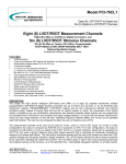
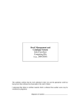
P/N 64PW3
TWO PWM SERVO AMPLIFIERS
VMEbus
TWO PWM SERVO AMPLIFIERS
with optional RS-422 serial data link, A/D, D/A or dual R/D
FEATURES:
• 5.0 A max. continuous; 8.5 A peak (per channel).
• Continuous background bit testing
SAFETY FEATURES: Interrupt will be set and Status registers will indicate:
• Drive fail: bias loss etc.
• Over-current condition
• Supply over-voltage condition
• Supply under-voltage condition
• Over temperature condition for PWM card
• Over temperature condition for Power Supply card
• Master Drive Enable
DESCRIPTION:
This conduction cooled card, incorporates two four-quadrant bi-directional PWM amplifiers that drive brush type,
(Optional brushless) DC motors, and optional RS-422, A/D, D/A or dual Resolver-to-Digital converters. The required 65
VDC power (other voltages are available) is supplied by a separate power supply module that is controlled by this card by
means of a pulse train. Contact factory for Optional programmable encoder (A & B) equivalent Hall Effect commutation
outputs.
The amplifiers can be set for either current or voltage control via the bus. Actual motor control, using the selected voltage
or current mode, can be done with the RS-422 link. Both output drives can be shut down via a single discrete opto-isolated
logic input. A thermal shutdown will prevent damage to the system caused by excessive temperature conditions. Motor
drive power is opto-isolated from VME power. Major diagnostics are incorporated that offer substantial
improvements to system reliability because user is immediately alerted to malfunctions. The processor monitors every
Safety characteristic and any failure triggers an Interrupt, and shut-down if applicable, with the results available in status
registers. The testing is totally transparent to the user, requires no external programming, has no effect on the standard
operation of this card and can be enabled or disabled via the bus. To simplify logistics, Part number, S/N, Date code, &
Rev. are located in non-volatile memory locations.
SPECIFICATIONS: PWM amplifiers (Apply after a 5 second warm up period)
65 VDC ±5% (Motor rails will be within 35 volts of the chassis)
Power:
Resolution:
Output (per channel):
Peak output voltage:
Frequency (PWM):
Band width:
Quiescent power:
Efficiency:
Heat to be dissipated:
Master Drive Enable:
Shut-down conditions:
12 bits. Monotonic over temperature range
5.0 A max. continuous, 8.5 A peak based on a card edge temperature of +85C. Short
circuit protected. Thermal protection will determine duration of peak current drive.
Supply voltage -2.4 V max. at 8.5 A peak
50 Khz
800 Hz open loop minimum in current mode with user programmable loop controller
variables.
TBD with no motors connected
At 65 VDC and 5.0 A: 96%
10 watts per amplifier
A discrete input (N/O), opto-isolated from the motor supply, must receive a +5 VDC
level to permit operation and cannot be overridden.
RS-422 time out
PWM card time out
Drive fail Ch.1: bias loss etc.
Drive fail Ch. 2: bias loss etc.
Supply over-voltage condition: 71.5 VDC
Supply under-voltage condition: 58.5 VDC
Over-temperature condition:
110°C at heat sink
North Atlantic Industries, Inc.
Apex Signal Division
110 Wilbur Place, Bohemia, NY 11716
631.567.1100/631.567.1823 (fax)
www.naii.com / e-mail: [email protected]
4/12/2002
Cage Code:OVGU1
64_PW3_2A001_Rev_3
Page 1 of 22
An H-bridge short will trigger an immediate shut down
Motor Output Ch. 1 shorted to ground
Motor Output Ch. 1 shorted to +VDC
Motor Output Ch. 2 shorted to ground
Motor Output Ch. 2 shorted to +VDC
A channel that is turned OFF by any ‘Shut-down condition’ except for Drive fail and
H-bridge short, can be returned to active status when ‘Shut-down condition’ becomes
normal by writing “1” to appropriate Drive Reset register.
Control of ext. Power: A pulse train signal between the Power Supply Module and the Motor Drive PWM
Module is used for ON/OFF and failure monitoring.
SPECIFICATIONS:
Definition:
RS-422 (Full Duplex) Serial Data link (Optional)
+ is non-inverted; – is inverted and internally terminated with 120Ω. One side is
pulled
up (1000 Ω) to +5 VDC and the other is pulled down (1000 Ω) to ground. When Logic
"1"is being transmitted, the High output will be +5 V and the Low output will be zero.
Clock rate:
2 Mhz, SLDC mode. User will generate the clock.
Clock edge:
Rising or Falling clock edge can be specified via VME bus.
Error status:
SDLC CRC checking is supported per IBM Specification GA27-3093-04. CRC error
status is available thru the VME interface. First status is a 16-bit word containing the
total number of CRC errors observed on the RX line pair. Second status is a 16-bit
word containing the total number of data frames received thru the RX line pair. The
third is a status bit indicating the status of the last data frame received (0=no CRC
error, 1=CRC error on last frame). The first and second status words will stop
counting when a max count of FFFF is reached. Clearing and restarting is thru the
VME interface.
Watchdog timer (RS485): With selectable time out period. When code is not received, drive power is shut down.
SPECIFICATIONS:
Number of A/D channels:
Resolution:
A/D Input voltage:
A/D Input impedance:
A/D Conversion Rate:
Number of D/A channels:
Resolution:
DA Output voltage:
D/A Load:
D/A Conversion rate:
Resolution:
Accuracy:
Tracking Rate:
Bandwidth:
Input format:
Input voltage:
Input Impedance:
Reference Input:
Reference Zin
Frequency:
Phase shift:
Velocity, Digital:
Wrap around Self Test:
North Atlantic Industries, Inc.
Apex Signal Division
110 Wilbur Place, Bohemia, NY 11716
A/D & D/A
TBD
12 bit, no missing codes
±10 VDC
10 K Ohms minimum
100 kSPS minimum
TBD
12 bit, guaranteed monotonic
±10 VDC
2 K Ohms minimum
100 kHz minimum
Resolver-to-digital:
16 bits
±1 arc-minute
150 RPS max. is standard with normal band width
Standard is 40 Hz at 400 Hz, and 100 Hz above 1 kHz. Can be programmed in field
From 5 Hz to 1200 Hz per channel.
Synchro or Resolver programmable.
2-28 VL-L, Autoranging,
40 kΩ min. Reference:
2-28 Vrms, Autoranging.
100 kΩ min.
400 Hz to 10 kHz
The synthetic reference circuit automatically compensates for phase shifts between
the transducer excitation and output up to ±60°.
16-bit resolution; Linearity: 0.1%. Scalable to 0.1°/sec resolution. BW is same as
Signal BW.
The three different powerful test methods are available.
631.567.1100/631.567.1823 (fax)
www.naii.com / e-mail: [email protected]
4/12/2002
Cage Code:OVGU1
64_PW3_2A001_Rev_3.doc
Page 2 of 22
SPECIFICATIONS:
General
Watchdog timer (VME):
Temperature, operating:
Storage temperature:
Stress screening:
With selectable time out period. When code is not received, drive power is shut down.
-40°C to +85°C card edge temperature
-55°C to +95°C
All boards are temperature cycled from -40°C to +85°C for 24 hours. The baseplate
temperature will be controlled to -40°C to +85°C.
60,000 feet
Data transfers within 200 ns.
A reliability prediction will be performed utilizing Mil-Hdbk-217, revision F, notice 2, in
an airborne rotary wing environment at a constant temperature of + 55 °C.
6U (9.2") height, 8HP (0.8") width.
TBD oz.
Altitude:
VME Data transfer:
MTBF:
Size:
Weight:
I/O CONFIGURATION:
The VMEbus interface will respond to A32:D16, A24:D16 and A16:D16 DTB cycles.
A32 mode: Unit responds to address modifiers 0A, 0D, 0E and 09. Base address can be set anywhere
in the 4 Gigabyte address space on 256 byte boundaries.
A24 mode: Responds to address modifiers 3A, 3D, 3E and 39. Base address can be set anywhere in
the 16 Megabyte address space on 256 byte boundaries.
A16 mode: Responds to address modifiers 2A, 2D, 2E and 29. Base address can be set anywhere in the 64 K byte
address space on 256 byte boundaries.
Enable Geographical Addressing by removing jumper from JP2.
Disable Geographical
Addressing by adding jumper to JP2.
When Geographical Addressing is enabled the card will respond to address modifier 2Fh for A24 Address mode,
where the 5 Msb’s of the A24 address are the 5 bits defined by the slot in VME back plane. The Card can
optionally be interrogated at 2Fh to determine resource requirements and available functionally. Using the
address modifier 2Fh, the following need to be written to the card:
1) The base address the card should respond to
2) The address modifier (A16, A24, A32)
3) Then enable the card.
For example: If the card is in slot # 10 the 5 Msb’s are 01010 so the address of the CSR registers are:
0101 0 111 1111 1111 xxxx xxxx or 57FFxx h ( xx is CSR register offset)
Write to address 57FF63 h, the A31 – A24 base address bits, for example 01h
Write to address 57FF67 h, the A23 – A16 base address bits, for example 02h
Write to address 57FF6B h, the A15 – A8 base address bits, for example 04h
Write to address 57FF6F h, the address modifier you wish to respond to shifted up 2 bits, for example
28h(0A<< 2)
Then Write to address 57FFFBh, 10h to enable the card.
The card will now respond to the base address (010204 in the example) and address modifier (0A in example)
programmed. The base address and address modifier can be changed at any time.
North Atlantic Industries, Inc.
Apex Signal Division
110 Wilbur Place, Bohemia, NY 11716
631.567.1100/631.567.1823 (fax)
www.naii.com / e-mail: [email protected]
4/12/2002
Cage Code:OVGU1
64_PW3_2A001_Rev_3.doc
Page 3 of 22
1.1 Memory Map
00
02
04
06
08
0A
0C
0E
10
12
14
16
18
1A
1C
1E
20
22
24
26
28
Current/Voltage select (Ch. 1 & 2) W/R
Command Source select (Ch 1 & 2) W/R
Drive Enable, Ch.1
W/R
Current command, Ch.1
W/R
Voltage command, Ch.1
W/R
Current limit, Ch.1
W/R
Current, measured Ch.1
R
Voltage, measured Ch.1
R
Drive Reset, Ch.1
W/R
Drive Enable, Ch.2
W/R
Current command, Ch.2
W/R
Voltage command, Ch.2
W/R
Current limit, Ch.2
W/R
Current, measured Ch.2
R
Voltage, measured Ch.2
R
Drive Reset, Ch.2
W/R
Interrupt Level
W/R
Interrupt Vector
W/R
Interrupt Enable
W/R
Kc Ch.1
W/R
Kg Ch.1
W/R
2A Ki Ch.1
2C Not used
2E Kp Ch.1
30 Kc Ch.2
32 Kg Ch.2
34 Ki Ch.2
36 Not used
38 Kp Ch.2
3A Rising/Falling clock edge
3C Total CRC errors observed
3E Total CRC Data Frames received
40 Clear CRC errors
42 Clear CRC Data Frames
44 Status, last Data Frame
46 Measured Supply voltage
48 RS422 Test Bits
4A RS422 Transmit Enable
4C Battlefield override
4E Status
50 DAC Test Word #1
52 DAC Test Word #2
W/R 54 ADC Input from Test connector
56 ADC Input Enable
W/R 58 ADC Input Loop Select
W/R 5A Watchdog timer (VME)
W/R 5C Watchdog timer (RS422)
W/R 5E Time out period, VME Watchdog timer
60 Time out period, RS422
W/R 62 Soft reset
W/R 64 Part number
R 66 Serial number
R 68 Date Code
W/R 6A Rev. Level, PCB
W/R 6C Rev. Level, Processor
R 6E Rev. Level, FPGA
R 70 Temperature, PWM 1
W/R 72 Temperature, PWM 2
W/R 74 Temperature, PS
W/R 76 PWM 1 duty cycle limit
R 78 PWM 2 duty cycle limit
R 7A Disable PS temp shut down
R
R
W/R
W/R
W/R
W/R
W/R
W/R
W/R
R
R
R
R
R
R
R
R
R
W/R
W/R
W/R
1.2 Register Definitions
All registers shall be defined as 16-bit in width. If no value is specified for a particular register or field within a
register, the register or field shall be initialized to 0’s. In the use of a boolean value for a two value register or
register field, valid values are 0000h or NOT 0000h, i.e. any other value other than 0000h and the module shall
respond correctly for any value of NOT 0000h. The preferred value for NOT 0000h shall be FFFFh, or in the
case of a register field which is a subset of the total register value, the preferred value for NOT 0h shall be the
maximum unsigned integer value for the field. As an example and 8-bit NOT 00h shall be FFh. Write Only
registers shall not be used. The value of any VME accessible register shall be readable via the VME bus.
1.2.1 Address: 00h
Description: PWM Module Current Mode/Voltage Mode Select
Type: Boolean
Range: 0000h or FFFFh
Read/Write: R/W
Initialized Value: 0000h
This register is used to select the motor drive topology used for both PWM channels, either current mode or
voltage mode. Definitions are as follows:
Reg. Value
0000h
FFFFh
Definition
Current Mode
Voltage Mode
Description
Current feedback loop wrapped around the motors
Voltage drive only, no current feedback
1.2.2 Address: 02h
Description: Command Source Select
Type: Boolean
Range: 0000h or FFFFh
Read/Write: R/W
Initialized Value: 0000h
This register is used for selecting the source of the motor current or voltage commands for both PWM channels.
Reg. Value
Definition
North Atlantic Industries, Inc.
Apex Signal Division
110 Wilbur Place, Bohemia, NY 11716
Description
631.567.1100/631.567.1823 (fax)
www.naii.com / e-mail: [email protected]
4/12/2002
Cage Code:OVGU1
64_PW3_2A001_Rev_3.doc
Page 4 of 22
0000h
RS-422 SDLC Commands come from the RS-422 SDLC interface
FFFFh
VME
Commands come from the VME registers
NOTES:
1. This register affects the R/W functionality of VME registers 06h, 08h, 14h, 16h. See the notes for those
specific registers.
1.2.3 Address: 04h
Description: Drive Enable, Channel 1
Type: Boolean
Range: 0000h or FFFFh
Read/Write: R/W
Initialized Value: 0000h
This register is used for PWM channel 1 drive enable control. Definitions are as follows:
Reg. Value
Definition
Description
0000h
Drive Disabled Motor drive is disabled for PWM channel 1
FFFFh
Drive Enabled Motor drive is enabled for PWM channel 1
NOTES:
1. When drive is disabled, also set voltage and current drive values to zero in registers 06h and 08h
1.2.4
Address: 06h
Description: Current Command, Channel 1
Type: 2’s Complement Integer
Range: F800h – 07FFh
Read/Write: Special
Initialized Value: 0000h
This register latches the PWM channel 1 current drive command when the module is operating in current mode
as defined by VME register 00h. The command is a 12-bit signed integer and is mapped into the LSB’s of the
VME 16-bit registers with sign bit extension.
Reg. Value
Definition
Description
F800h
Max Neg Value Value of -2048, equates to -8.5 A
07FFh
Max Pos Value Value of +2047, equates to +8.496 A
NOTES:
1.When VME register 02h is set to FFFFh, this register is R/W as this register is the source of the command
word.
2.When VME register 02h is set to 0000h, this register is R only as the source of the command is the RS-422
SDLC interface.
1.2.5
Address: 08h
Description: Voltage Command, Channel 1
Type: 2’s Complement Integer
Range: F800h – 07FFh
Read/Write: Special
Initialized Value: 0000h
This register latches the PWM channel 1 voltage drive command when the module is operating in voltage mode
as defined by VME register 00h. The command is a 12-bit signed integer and is mapped into the LSB’s of the
VME 16-bit registers with sign bit extension.
Reg. Value
Definition
Description
F800h
Max Neg Value Value of -2048
07FFh
Max Pos Value Value of +2047
NOTES:
1. When VME register 02h is set to FFFFh, this register is R/W because it is the source of the command word.
2. When VME register 02h is set to 0000h, this register is R only as the source of the command is the RS-422
SDLC interface.
North Atlantic Industries, Inc.
Apex Signal Division
110 Wilbur Place, Bohemia, NY 11716
631.567.1100/631.567.1823 (fax)
www.naii.com / e-mail: [email protected]
4/12/2002
Cage Code:OVGU1
64_PW3_2A001_Rev_3.doc
Page 5 of 22
1.2.6
Address: 0Ah
Description: Current Limit, Channel 1
Type: 2’s Complement Integer
Range: 0000h – 7FFFh
Read/Write: R/W
Initialized Value: 0000h
This register controls the maximum allowable current sourced by PWM channel 1. Since the register value is
defining the maximum allowable positive or negative current only positive 16-bit numbers are used. Negative
numbers will be latched as a value of zero.
Reg. Value
Definition
Description
0000h
Minimum Value Zero equates to zero drive current
7FFFh
Maximum Value 32767 equates to 9.995A maximum drive current
NOTES:
1. Negative values will be treated as zero and the VME readback shall indicated a register value of zero.
1.2.7
Address: 0Ch
Description: Current Feedback, Channel 1
Type: 2’s Complement Integer
Range: F800h – 07FFh
Read/Write: R/W
Initialized Value: 0000h
This register contains the measured motor current value in PWM channel 1. Overflow or underflow values shall
be clamped at the maximum positive or negative values. This value is sent to the Ch1 test point DAC with a
scaling 1A/V.
Reg. Value
Definition
Description
F800h
Max Neg Value -2048 equates to –10.0A
07FFh
Max Pos Value +2047 equates to +9.995A
NOTES:
1. Current values in excess of –10A or +9.995A shall be clamped to –2048 or +2047 respectively within the
VME register.
1.2.8
Address: 0Eh
Description: Voltage Feedback, Channel 1
Type: 2’s Complement Integer
Range: F800h – 07FFh
Read/Write: R/W
Initialized Value: 0000h
This register contains the actual motor voltage value (including applied potential to overcome motor back emf
when operating in current mode.) in PWM channel 1 and is scaled according to the maximum potential of
79.96V. Overflow and underflow values shall be clamped at the maximum positive or negative values
Reg. Value
Definition
Description
F800h
Max Neg Value -2048 equates to –80.000V
07FFh
Max Pos Value +2047 equates to +79.960V
NOTES:
1. Voltage values in excess of –80.000V or +79.960V shall be clamped to –2048 or +2047 respectively within the
VME register.
1.2.9
Address: 10h
Description: Drive Reset, Channel 1
Type: Boolean
North Atlantic Industries, Inc.
Apex Signal Division
110 Wilbur Place, Bohemia, NY 11716
631.567.1100/631.567.1823 (fax)
www.naii.com / e-mail: [email protected]
4/12/2002
Cage Code:OVGU1
64_PW3_2A001_Rev_3.doc
Page 6 of 22
Range: 0000h or FFFFh
Read/Write: R/W
Initialized Value: 0000h
This register is used to clear all fail conditions related to PWM channel 1 in the VME status register address 4Eh.
Reg. Value
Definition
Description
0000h
No Action
Inactive State
FFFFh
Clear Fails
Attempt to clear the PWM channel 1 fail status
NOTES:
1. This is implemented as a non-latched register value, i.e. upon writing a FFFFh do not need to write a 0000h to
return the register to an inactive state.
2. Drive Reset: In the event of a shut-down fault condition the drive will be disabled. The specific fault condition
is shown in the status register. To restore normal operation, write a “1” to the Drive Reset Register. This
attempts to clear any fault conditions. If fault conditions are cleared (by checking status bits) the drive can be
re-enabled via the Drive enable register.
1.2.10
Address: 12h
Description: Drive Enable, Channel 2
Type: Boolean
Range: 0000h or FFFFh
Read/Write: R/W
Initialized Value: 0000h
This register is used for PWM channel 2 drive enable control. Definitions are as follows:
Reg. Value
Definition
Description
0000h
Drive Disabled
Motor drive is disabled for PWM channel 2
FFFFh
Drive Enabled
Motor drive is enabled for PWM channel 2
NOTES:
1. When drive is disabled, also set voltage and current drive values to zero in registers 14h and 16h
1.2.11
Address: 14h
Description: Current Command, Channel 2
Type: 2’s Complement Integer
Range: F800h – 07FFh
Read/Write: Special
Initialized Value: 0000h
This register latches the PWM channel 2 current drive command when the module is operating in current mode
as defined by VME register 00h. The command is a 12-bit signed integer and is mapped into the LSB’s of the
VME 16-bit registers with sign bit extension.
Reg. Value
Definition
Description
F800h
Max Neg Value Value of -2048, equates to -8.5 A
07FFh
Max Pos Value Value of +2047, equates to +8.496 A
NOTES:
1. When VME register 02h is set to FFFFh, this register is R/W because it is the source of the command word.
2. When VME register 02h is set to 0000h, this register is R only because the source of command is the RS-422
SDLC interface.
1.2.12
Address: 16h
Description: Voltage Command, Channel 2
Type: 2’s Complement Integer
Range: F800h – 07FFh
Read/Write: Special
Initialized Value: 0000h
This register latches the PWM channel 2 voltage drive command when the module is operating in voltage mode
as defined by VME register 00h. The command is a 12-bit signed integer and is mapped into the LSB’s of the
VME 16-bit registers with sign bit extension.
Reg. Value Definition
F800h
Max Neg Value
North Atlantic Industries, Inc.
Apex Signal Division
110 Wilbur Place, Bohemia, NY 11716
Description
Value of -2048
631.567.1100/631.567.1823 (fax)
www.naii.com / e-mail: [email protected]
4/12/2002
Cage Code:OVGU1
64_PW3_2A001_Rev_3.doc
Page 7 of 22
07FFh
Max Pos Value
Value of +2047
NOTES:
1. When VME register 02h is set to FFFFh, this register is R/W because it is the source of the command word.
2. When VME register 02h is set to 0000h, this register is R only as the source of the command is the RS-422
SDLC interface.
1.2.13
Address: 18h
Description: Current Limit, Channel 2
Type: 2’s Complement Integer
Range: 0000h – 7FFF
Read/Write: R/W
Initialized Value: 0000h
This register controls the maximum allowable current sourced by PWM channel 2. Since the register value is
defining the maximum allowable positive or negative current only positive 16-bit numbers are used. Negative
numbers will be latched as a value of zero.
Reg. Value
Definition
Description
0000h
Minimum Value Zero equates to zero drive current
7FFFh
Maximum Value 32767 equates to 9.995A maximum drive current
NOTES:
1. Negative values will be treated as zero and the VME readback shall indicated a register value of zero.
1.2.14
Address: 1Ah
Description: Current Feedback, Channel 2
Type: 2’s Complement Integer
Range: F800h – 07FFh
Read/Write: R/W
Initialized Value: 0000h
This register contains the measured motor current value in PWM channel 2. Overflow or underflow values shall
be clamped at the maximum positive or negative values. This value is sent to the Ch2 test point DAC with a
scaling 1A/V.
Reg. Value
Definition
Description
F800h
Max Neg Value -2048 equates to –10.0A
07FFh
Max Pos Value +2047 equates to +9.995A
NOTES:
1. Current values in excess of –10.0A or +9.995A shall be clamped to –2048 or +2047 respectively within the
VME register.
1.2.15
Address: 1Ch
Description: Voltage Feedback, Channel 2
Type: 2’s Complement Integer
Range: F800h – 07FFh
Read/Write: R/W
Initialized Value: 0000h
This register contains the actual motor voltage value (including applied potential to overcome motor back emf
when operating in current mode.) in PWM channel 2 and is scaled according to the maximum potential of 65V.
Overflow and underflow values shall be clamped at the maximum positive or negative values
Reg. Value
Definition
Description
F800h
Max Neg Value -2048 equates to –80.000V
07FFh
Max Pos Value +2047 equates to +79.960V
NOTES:
1. Voltage values in excess of –80.000V or +79.960V shall be clamped to –2048 or +2047 respectively within the
VME register.
1.2.16
Address: 1Eh
Description: Drive Reset, Channel 2
Type: Boolean
Range: 0000h or FFFFh
North Atlantic Industries, Inc.
Apex Signal Division
110 Wilbur Place, Bohemia, NY 11716
631.567.1100/631.567.1823 (fax)
www.naii.com / e-mail: [email protected]
4/12/2002
Cage Code:OVGU1
64_PW3_2A001_Rev_3.doc
Page 8 of 22
Read/Write: R/W
Initialized Value: 0000h
This register is used to clear any fail conditions related to PWM channel 2 in VME status register at address 4Eh.
Reg. Value
Definition
Description
0000h
No Action
Inactive State
FFFFh
Clear Fails
Attempt to clear the PWM channel 2 fail status
NOTES:
1. This is implemented as a non-latched register value, i.e. upon writing a FFFFh do not need to write a 0000h to
return the register to an inactive state.
2. Drive Reset: In the event of a shut-down fault condition the drive will be disabled. The specific fault condition
is shown in the status register. To restore normal operation write a “1” to the Drive Reset Register. This
attempts to clear any fault conditions. If fault conditions are cleared (by checking status bits) the drive can be
re-enabled via the Drive enable register.
1.2.17
Address: 20h
Description: VME Interrupt Level
Type: Integer
Range: 0-7
Read/Write:
Initialized Value: 0000h
1.2.18
Address: 22h
Description: VME Interrupt Vector
Type:
Range:
Read/Write:
Initialized Value: 0000h
Interrupt Vector: Write 8 bit word (0-255).
1.2.19
Address: 24h
Description: VME Interrupt Enable
Type:
Range:
Read/Write:
Initialized Value: 0000h
The bit fields in this register correspond to the bit fields in the Status Register. Writing a “1” to a bit will enable an
interrupt. This allows any status register condition to cause an interrupt with the exception of the Master Enable
Switch.
1.2.20
Address: 26h
Description: Kc Channel 1, Input Command Scaling for PWM Channel 1
Type: 2’s Complement Integer
Range: 8000h – 7FFFh
Read/Write: R/W
Initialized Value: 0000h
This register is used to set the input voltage or current command scaling for input into the PWM channel 1 motor
loop controller.
Reg. Value
Definition
Description
8000h
Max Neg Value -32768 equates to –80V or –8.5A
7FFFh
Max Pos Value +32767 equates to +79.960V or +8.5A
NOTES:
1. A negative scale factor effectively indicates a polarity reversal of the command and should be handled as such.
North Atlantic Industries, Inc.
Apex Signal Division
110 Wilbur Place, Bohemia, NY 11716
631.567.1100/631.567.1823 (fax)
www.naii.com / e-mail: [email protected]
4/12/2002
Cage Code:OVGU1
64_PW3_2A001_Rev_3.doc
Page 9 of 22
1.2.21
Address: 28h
Description: Kg Channel 1, Global Gain for PWM Channel 1 Motor Loop PI Controller
Type: 2’s Complement Integer
Range: 8000h – 7FFFh
Read/Write: R/W
Initialized Value: 0000h
This register is used to define the PWM channel 1 motor loop controller global gain constant used when the
module is configured as a current mode driver.
Reg. Value
8000h
7FFFh
1.2.22
Definition
Max Neg Value
Max Pos Value
Description
-32768
+32767
Scaling
-10
+10
Address: 2Ah
Description: Ki Channel 1, Integral Gain for PWM Channel 1 Motor Loop PI Controller
Type: 2’s Complement Integer
Range: 8000h – 7FFFh
Read/Write: R/W
Initialized Value: 0000h
This register is used to define the PWM channel 1 integral gain constant used within the current mode motor
loop PI controller.
Reg. Value
8000h
7FFFh
1.2.23
Definition
Max Neg Value
Max Pos Value
Description
-32768
+32767
Scaling
-25000 (Driven by sample rate)
+25000
Address: 2Ch (NOT IMPLEMENTED)
Description: Channel 1 Current Mode PI Controller Integral Term Limit
Type: Unsigned Integer
Range: 0000h – FFFFh
Read/Write: R/W
Initialized Value: 0000h
This register is used to limit the PWM channel 1 PI controller integral term contribution to the motor drive output.
The value is used to relate the percentage of the output signal to the PWM drive bridge that the integral term of
the PI controller can grow to. This register in no way shall be used to limit the proportional term of the PI
controller.
Reg. Value
0000h
FFFFh
1.2.24
Definition
Minimum Value
Maximum Value
Description
0% of output signal contribution
100% of output signal contribution
Address: 2Eh
Description: Kp Channel 1, Proportional Gain for PWM Channel 1 Motor Loop PI Controller
Type: 2’s Complement Integer
Range: 8000h – 7FFFh
Read/Write: R/W
Initialized Value: 0000h
This register is used to define the PWM channel 1 proportional gain constant used within the current mode motor
loop PI controller.
Reg. Value
8000h
7FFFh
1.2.25
Definition
Max Neg Value
Max Pos Value
Description
-32768
+32767
Scaling
-2
+2
Address: 30h
Description: Kc Channel 2, Input Command Scaling for PWM Channel 2
Type: 2’s Complement Integer
Range: 8000h – 7FFFh
North Atlantic Industries, Inc.
Apex Signal Division
110 Wilbur Place, Bohemia, NY 11716
631.567.1100/631.567.1823 (fax)
www.naii.com / e-mail: [email protected]
4/12/2002
Cage Code:OVGU1
64_PW3_2A001_Rev_3.doc
Page 10 of 22
Read/Write: R/W
Initialized Value: 0000h
This register is used to set the input voltage or current command scaling for input into the PWM channel 2 motor
loop controller.
Reg. Value
Definition
Description
8000h
Max Neg Value -32768 equates to –80V or –8.5A
7FFFh
Max Pos Value +32767 equates to +79.960V or +8.5A
NOTES:
1. A negative scale factor effectively relates to a polarity reversal of the command and should be handled as
such.
1.2.26
Address: 32h
Description: Kg Channel 2, Global Gain for PWM Channel 2 Motor Loop PI Controller
Type: 2’s Complement Integer
Range: 8000h – 7FFFh
Read/Write: R/W
Initialized Value: 0000h
This register is used to define the PWM channel 2 motor loop controller global gain constant used when the
module is configured as a current mode driver.
Reg. Value
8000h
7FFFh
1.2.27
Definition
Max Neg Value
Max Pos Value
Description
-32768
+32767
Scaling
-10
+10
Address: 34h
Description: Ki Channel 2, Integral Gain for PWM Channel 2 Motor Loop PI Controller
Type: 2’s Complement Integer
Range: 8000h – 7FFFh
Read/Write: R/W
Initialized Value: 0000h
This register is used to define the PWM channel 2 integral gain constant used within the current mode motor
loop PI controller.
Reg. Value
8000h
7FFFh
1.2.28
Definition
Max Neg Value
Max Pos Value
Description
Scaling
-32768
-25000 (Driven by sampling rate
+32767
+25000
Address: 36h (NOT IMPLEMENTED)
Description: Channel 2 Current Mode PI Controller Integral Term Limit
Type: Unsigned Integer
Range: 0000h – FFFFh
Read/Write: R/W
Initialized Value: 0000h
This register is used to limit the PWM channel 2 PI controller integral term contribution to the motor drive output.
The value is used to relate the percentage of the output signal to the PWM drive bridge that the integral term of
the PI controller can grow to. This register in no way shall be used to limit the proportional term of the PI
controller.
Reg. Value
0000h
FFFFh
1.2.29
Definition
Minimum Value
Maximum Value
Description
0% of output signal contribution
100% of output signal contribution
Address: 38h
Description: Kp Channel 2, Proportional Gain for PWM Channel 2 Motor Loop PI Controller
Type: 2’s Complement Integer
Range: 8000h – 7FFFh
Read/Write: R/W
North Atlantic Industries, Inc.
Apex Signal Division
110 Wilbur Place, Bohemia, NY 11716
631.567.1100/631.567.1823 (fax)
www.naii.com / e-mail: [email protected]
4/12/2002
Cage Code:OVGU1
64_PW3_2A001_Rev_3.doc
Page 11 of 22
Initialized Value: 0000h
This register is used to define the PWM channel 2 proportional gain constant used within the current mode motor
loop PI controller.
Reg. Value
8000h
7FFFh
1.2.30
Definition
Max Neg Value
Max Pos Value
Description Scaling
-32768
-2
+32767
+2
Address: 3Ah
Description: RS-422 SDLC Rising/Falling Clock Edge Select
Type: Boolean
Range: 0000h or FFFFh
Read/Write: R/W
Initialized Value: 0000h
This register is used to select the clock edge used by the RS-422 SDLC serial port. Transmit and receive
functions will use opposite edges as defined in the following table
Reg. Value
0000h
FFFFh
1.2.31
Definition
Description
Tx falling edge, Rx rising edge
Tx rising edge, Rx falling edge
Address: 3Ch
Description: Total RS-422 SDLC CRC Errors Observed
Type: Unsigned Integer
Range: 0000h – FFFFh
Read/Write: R
Initialized Value: 0000h
This register is used to capture RS-422 SDLC Receive Data Frame CRC errors. Whenever a CRC error is
detected within a received data frame this register will increment its value unless VME register is 42h is
commanding a clear/reset state. If the maximum count value is received the register will stop counting and retain
the max count value until cleared, i.e. it will not roll the count value back to 0000h and continue counting
Reg. Value
Definition
Description
0000h
Min Count Value No RS-422 SDLC errors observed
FFFFh
Max Count Value At least 65535 RS-422 SDLC errors observed
NOTES:
1.When VME register 42h is commanding a clear, this register will reset to value 0000h and will not increment
its count until VME register 42h has stopped commanding a clear.
1.2.32
Address: 3Eh
Description: Total RS-422 SDLC Data Frames Received
Type: Unsigned Integer
Range: 0000h – FFFFH
Read/Write: R
Initialized Value: 0000h
This register is used to capture the number of RS-422 SDLC Data Frames received, valid or invalid. If the
maximum count value is received the register will stop counting and retain the max count value until cleared, i.e.
it will not roll the count value back to 0000h and continue counting.
Reg. Value
Definition
Description
0000h
Min Count Value No RS-422 SDLC data frames received
FFFFh
Max Count Value At least 65535 RS-422 SDLC data frames received
NOTES:
1.When VME register 40h is commanding a clear, this register will reset to value 0000h and will not increment its
count until VME register 40h has stopped commanding a clear.
1.2.33
Address: 40h
Description: Clear RS-422 SDLC Errors Observed
North Atlantic Industries, Inc.
Apex Signal Division
110 Wilbur Place, Bohemia, NY 11716
631.567.1100/631.567.1823 (fax)
www.naii.com / e-mail: [email protected]
4/12/2002
Cage Code:OVGU1
64_PW3_2A001_Rev_3.doc
Page 12 of 22
Type: Boolean
Range: 0000h or FFFFh
Read/Write: R/W
Initialized Value: 0000h
This register is used to clear the RS-422 SDLC CRC error counter in VME register 3Eh. While is register value is
in the inactive/no clear state the status register is allowed to increment its count value. When the active/clear
state is commanded the status register shall clear its count value to 0000h and retain that count value without
incrementing until this register value has returned to the inactive state.
Reg. Value
Definition
Description
0000h
Inactive/ No Clear VME register 3Ch enabled to count
FFFFh
Active/Clear
VME register 3Ch cleared
1.2.34
Address: 42h
Description: Clear RS-422 SDLC Data Frames Received
Type: Boolean
Range: 0000h or FFFFh
Read/Write: R/W
Initialized Value: 0000h
This register is used to clear the RS-422 SDLC CRC data frame counter in VME register 40h. While the register
value is in the inactive/no clear state the status register is allowed to increment its count value. When the
active/clear state is commanded the status register shall clear its count value to 0000h and retain that count
value without incrementing until this register value has returned to the inactive state.
Reg. Value
Definition
Description
0000h
Inactive/ No Clear VME register 3Eh enabled to count
FFFFh
Active/Clear
VME register 3Eh cleared
1.2.35
Address: 44h
Description: Error Status of Last RS-422 SDLC Data Frame
Type: Boolean
Range: 0000h or FFFFh
Read/Write: R/W
Initialized Value: 0000h
This register is used to indicate the status of the last RS-422 SDLC data frame received. If a data frame is
interrupted for any reason an error indication shall be indicated within this register. This register shall retain the
status of the last data frame received until another data frame transmission has completed and new status is
available to update this register value.
Reg. Value
Definition
0000h
Last Frame Valid
FFFFh
Last Frame Error
1.2.36
Description
The last RS-422 SDLC data frame received had no errors
The last RS-422 SDLC data frame received had an error
Address: 46h
Description: Measured PWM Positive Supply Voltage
Type: 2’s Complement Integer
Range: 8000 – 7FFFh
Read/Write: R
Initialized Value: 0000h
This register is used to indicate the positive voltage rail of the PWM h-bridge output.
Reg. Value
0000h
07FFh
Definition
Min Value
Max Value
North Atlantic Industries, Inc.
Apex Signal Division
110 Wilbur Place, Bohemia, NY 11716
Description
0V observed on PWM power supply
+79.96V observed on PWM power supply
631.567.1100/631.567.1823 (fax)
www.naii.com / e-mail: [email protected]
4/12/2002
Cage Code:OVGU1
64_PW3_2A001_Rev_3.doc
Page 13 of 22
1.2.37
Address: 48h
Description: RS422 Test Bits
Type: Integer
Range: 0000 – 000Fh
Read/Write: R/W
Initialized Value: 0000h
The least significant 4 bits of this register (D3 – D0) are transmitted by the RS422 interface whenever the ADC
reading is enabled to be transmitted via registers 56h & 58h
1.2.38
Address: 4Ah
Description: RS422 Transmit Enable
Type: Boolean
Range: 0000h or FFFFh
Read/Write: R/W
Initialized Value: 0000h
This register enables SDLC transmission of a frame after receipt of a valid frame. A value of 0000h disables
transmission, a value of FFFFh enables transmission.
1.2.39
Address 4Ch
Description: Battlefield Override Command
Type: Boolean
Range: 0000h or FFFFh
Read/Write: R/W
Initialized Value: 0000h
This register is used to lockout all fail-safes within the PWM module and/or PS module. When active, no
intervention of the protection circuitry to shut drive off to either PWM channel is allowed (except for Watchdog
timer 5Eh or 60h) however the status of any protection logic shall be updated within the VME register 4Eh to
indicate a failure exists.
Reg. Value
0000h
FFFFh
1.2.39
Definition
Inactive
Active
Description
Normal operation, protection circuitry enabled
Failsafe lockout, protection circuitry disabled
Address: 4Eh
Description: PWM Module Status Register
Type: Discrete
Range: See Below for Bit Definitions
Read/Write: R
Initialized Value: 0000h
This register is used to indicate hardware status for the PWM and PS modules.
MSB
D15
D14
Reg. Field
D0
D1
D2
D3
D4
D5
D6
D7
D8
D9
D10
D14
D12
D11
Status Register Bit Field Identifiers
D10
D9
D8
D7
D6
D5
Identifier
Power Supply Over-voltage
Power Supply Under-voltage
PWM 1 Module Over-temp
PWM 2 Module Over-temp
PS Module Over-temp
Drive Fault PWM 1
Drive Fault PWM 2
RS-422 SDLC access timeout
VME access timeout
Not implemented
Not implemented
North Atlantic Industries, Inc.
Apex Signal Division
110 Wilbur Place, Bohemia, NY 11716
D4
D3
D2
D1
LSB
D0
Status Definition
0=normal, 1=fail
0=normal, 1=fail
0=normal, 1=PWM module over-temp
0=normal, 1=PWM module over-temp
0=normal, 1=PS module over-temp
0=normal, 1=fault
0=normal, 1=fault
0=normal, 1=watchdog timeout (VME register 5Ah)
0=normal, 1=watchdog timeout (VME register 5Ch)
0=normal, 1=PWM 1 over-current
0=normal, 1=PWM 2 over-current
631.567.1100/631.567.1823 (fax)
www.naii.com / e-mail: [email protected]
4/12/2002
Cage Code:OVGU1
64_PW3_2A001_Rev_3.doc
Page 14 of 22
D11
D12
D13
D14
D15
Not used
Not used
Drive Shut-Down PWM 1
Drive Shut-Down PWM 2
Master Drive Enable
Not used
Not used
0=normal, 1=Shutdown (clear with reset command)
0=normal, 1=Shutdown (clear with reset command)
0=enabled (sw. closed), 1=disabled (sw. open)
NOTES:
1. Over-voltage/Under-voltage is defined as <10%>/<10%> percent of nominal power supply voltage of 65V.
2. PWM over-temp is defined as a sensed temperature in excess of 110 deg C at heat sink.
3. PS over-temp is defined as a sensed temperature in excess of 100 deg C at base plate.
4. Master Drive enable is an external mechanical SPST switch closure used to indicate that it is acceptable to
enable motor drive.
5. Refer to VME register 5Ch information for description of RS-422 SDLC access timeout
6. Refer to VME register 5Ah information for description of VME access timeout
1.2.40
Address: 50h
Description: Test Word Output # 1 (On DAC Channel # 3)
Type: 2’s Complement Integer
Range: F800h – 07FFh
Read/Write: R
Initialized Value: 0000h
This register provides VME read access to the RS-422 SDLC receive data for DAC test word #1, the first of two
Digital to Analog test words used to provide general purpose analog output thru the RS-422 SDLC interface.
Since the SDLC data frames contain 12-bit words the data is mapped into the lsb’s of the VME register with sign
bit preservation.
Reg. Value
Definition
Description
F800h
Max Neg Value -2048 equates to –10V on the DAC #3 output channel
07FFh
Max Pos Value +2047 equates to +9.995V on the DAC #3 output channel
NOTES:
1.The PWM module receive data frame does not always necessarily contain the test word channels to be valid.
2.If no test word is transmitted or if an error is detected in the SDLC data frame, the last valid Test Word #1
value will be output on DAC #3.
1.2.41
Address: 52h
Description: Test Word Output # 2 (On DAC Channel # 4)
Type: 2’s Complement Integer
Range: F800h – 07FFh
Read/Write: R
Initialized Value: 0000h
This register provides VME read access to the RS-422 SDLC receive data for DAC test word #2, the second of
two Digital to Analog test words used to provide general purpose analog output thru the RS-422 SDLC interface.
Since the SDLC data frames contain 12-bit words the data is mapped into the lsb’s of the VME register with sign
bit preservation.
Reg. Value
Definition
Description
F800h
Max Neg Value -2048 equates to –10V on the DAC #4 output channel
07FFh
Max Pos Value +2047 equates to +9.995V on the DAC #4 output channel
NOTES:
1. The PWM module receive data frame does not always necessarily contain the test word channels to be valid.
2. If no test word is transmitted or if an error is detected in the SDLC data frame, the last valid Test Word #2
value will be output on DAC #4.
1.2.42
Address: 54h
Description: ADC Test Word Input
Type: 2’s Complement Integer
Range: F800h – 07FFh
North Atlantic Industries, Inc.
Apex Signal Division
110 Wilbur Place, Bohemia, NY 11716
631.567.1100/631.567.1823 (fax)
www.naii.com / e-mail: [email protected]
4/12/2002
Cage Code:OVGU1
64_PW3_2A001_Rev_3.doc
Page 15 of 22
Read/Write: R
Initialized Value: 0000h
This register provides VME read access to the RS-422 SDLC transmit data for the ADC test word, an Analog to
Digital test word used to provide general purpose analog input thru the RS-422 SDLC interface. Since the SDLC
data frames contain 12-bit words the data is mapped into the lsb’s of the VME register with sign bit preservation.
Reg. Value
Definition
Description
F800h
Max Neg Value -2048 equates to –10V on the ADC input channel
07FFh
Max Pos Value +2047 equates to +9.995V on the ADC input channel
NOTES:
1. The PWM module will only transmit this data when VME register 54h contains a valid transmit enable value.
2. If the SDLC transmit is not enabled, it is acceptable to latch the last transmitted value in this VME register and
does not need to be cleared upon a disable command in the VME register 54h.
1.2.43
Address: 56h
Description: ADC Test Word Input Enable
Type: Boolean
Range: 0000h or FFFFh
Read/Write: R/W
Initialized Value: 0000h
This register is used to enable or disable the ADC input test word for either transmission over the RS-422 SDLC
interface or injection into the PWM module channel control loop summing junctions. This register is only used to
determine if the word is enabled or not, the actual destination is determined by VME register 58h below.
Reg. Value
0000h
FFFFh
1.2.44
Definition
Disabled
Enable
Description
ADC input word is not enabled
ADC input word is enabled
Address: 58h
Description: ADC Test Word Input Destination Select
Type: Special
Range: 0000h, 5555h, or AAAAh
Read/Write: R/W
Initialized Value: 0000h
This register is used to select the destination for the ADC Test Input Word. The available destinations are either
the RS-422 SDLC interface or the summing junctions of the PWM Channel Loop Controllers. If the PWM module
is operating in a voltage mode, then the ADC input word will be added to the command voltage up to the
allowable saturation limits. If the PWM module is operating in a current mode, then the ADC input word is
injected into the feed-back summing junction of the loop controller. The purpose of this register is to allow Lab
analysis of the PWM loop controller for verification purposes of the loop characteristics.
When the ADC input word is injected into the feedback summary junction, the scaling is 07FFh=8.5A (10V input
to ADC=8.5A)
Reg. Value
0000h
5555h
AAAAh
Definition
RS-422
PWM Ch 1
PWM Ch 2
Description
ADC input is transmitted on RS-422 SDLC interface
ADC input is summed into PWM Ch 1 Loop Controller
ADC input is summed into PWM Ch 2 Loop Controller
NOTES:
1. Only the above three valid values are allowed. If any value other than the above three values is used, the
PWM module shall act as the ADC input word is not enabled and will not send the digitized data to any of the
three available locations defined above.
1.2.45
Address: 5Ah
Description: VME Activity Monitor Watchdog Timer Enable
Type: Boolean
Range: 0000h or FFFFh
Read/Write: R/W
Initialized Value: 0000h
North Atlantic Industries, Inc.
Apex Signal Division
110 Wilbur Place, Bohemia, NY 11716
631.567.1100/631.567.1823 (fax)
www.naii.com / e-mail: [email protected]
4/12/2002
Cage Code:OVGU1
64_PW3_2A001_Rev_3.doc
Page 16 of 22
This register provides enable or disable control of the VME activity watchdog timer defined in VME register 5Ah.
Reg. Value
0000h
FFFFh
1.2.46
Definition
Disabled
Enabled
Description
VME activity watchdog timer disabled
VME activity watchdog timer enabled
Address: 5Ch
Description: RS-422 SDLC Activity Monitor Watchdog Timer Enable
Type: Boolean
Range: 0000h or FFFFh
Read/Write: R/W
Initialized Value: 0000h
This register provides enable or disable control of the RS-422 SDLC activity watchdog timer defined in VME
register 5Ch.
Reg. Value
0000h
FFFFh
1.2.47
Definition
Disabled
Enabled
Description
RS-422 SDLC activity watchdog timer disabled
RS-422 SDLC activity watchdog timer enabled
Address: 5Eh
Description: VME Activity Monitor Watchdog Timeout Interval
Type: Unsigned Integer
Range: 0000h – FFFFh
Read/Write: R/W
Initialized Value: 0000h
This register provides the capability to define the watchdog timeout interval for a VME activity monitor. If the
watchdog timer is enabled via VME register 5Ah, the PWM module shall monitor accesses to the PWM module
status register at VME register 4Eh. If the status register is not accessed within the interval defined below, the
PWM module shall disable both PWM output channels even if the battlefield override command is enabled per
VME register 4Ch. The watchdog timeout status will also be updated within VME register 4Eh.
Reg. Value
0000h
FFFFh
1.2.48
Definition
Min Value
Max Value
Description
Zero equates to 0 milliseconds
65535 equates to 250 milliseconds
Address: 60h
Description: RS-422 SDLC Activity Monitor Watchdog Timeout Interval
Type: Unsigned Integer
Range: 0000h – FFFFh
Read/Write: R/W
Initialized Value: 0000h
This register provides the capability to define the watchdog timeout interval for a RS-422 SDLC activity monitor.
If the watchdog timer is enabled via VME register 5Ch, the PWM module shall monitor valid RS-422 SDLC
receive data frames. If a valid SDLC receive data frame is not received within the interval defined below, the
PWM module shall disable both PWM output channels even if the battlefield override command is enabled per
VME register 4Ch. The watchdog timeout status will also be updated within VME register 4Eh.
Reg. Value
0000h
FFFFh
1.2.49
Definition
Min Value
Max Value
Description
Zero equates to 0 milliseconds
65535 equates to 250 milliseconds
Address: 62h
Description: Module Soft Reset
Type: Boolean
Range: 0 or 1
Read/Write: W
Initialized Value: 0
North Atlantic Industries, Inc.
Apex Signal Division
110 Wilbur Place, Bohemia, NY 11716
631.567.1100/631.567.1823 (fax)
www.naii.com / e-mail: [email protected]
4/12/2002
Cage Code:OVGU1
64_PW3_2A001_Rev_3.doc
Page 17 of 22
This register is used to command a power on reset for the PWM and PS modules. Upon receiving a valid soft
reset command sequence, both modules shall re-initialize to the power on state as quickly as possible. Soft
Reset is Level sensitive. Writing a “1” initiates and holds software in reset state; then writing “0” initiates reboot
(depending upon configuration, takes up to 3 seconds). This function is equivalent to a power-on reset where all
parameters are reset to their default condition.
1.2.50
Address: 64h
Description: Module Part Number
Type: Integer
Read/Write: R
Initialized Value: N/A
Part Number: 15025
1.2.51
Address: 66h
Description: Module Serial Number
Type: Integer
Read/Write: R
Initialized Value: N/A
1.2.52
Address: 68h
Description: Module Date Code
Type: Integer
Range: YYWW (Ex.0224 indicates week 24 of year 2002)
Read/Write: R
Initialized Value: N/A
1.2.53
Address: 6Ah
Description: Revision Level of PCB (raw board)
Type: Integer
Read/Write: R
Initialized Value: N/A
1.2.54
Address: 6Ch
Description: Revision Level of Processor
Type: Integer
Read/Write: R
Initialized Value: N/A
1.2.55
Address: 6Eh
Description: Revision Level of FPGA
Type: Integer
Read/Write: R
Initialized Value: N/A
1.2.56
Address: 70h
Description: Temperature PW 1
Type: Signed Integer
Read/Write: R
Initialized Value: N/A
Range: -32768 to 32767 (Temperature in degrees C)
1.2.57
Address: 72h
Description: Temperature PW 2
Type: Signed Integer
Read/Write: R
Initialized Value: N/A
North Atlantic Industries, Inc.
Apex Signal Division
110 Wilbur Place, Bohemia, NY 11716
631.567.1100/631.567.1823 (fax)
www.naii.com / e-mail: [email protected]
4/12/2002
Cage Code:OVGU1
64_PW3_2A001_Rev_3.doc
Page 18 of 22
Range: -32768 to 32767 (Temperature in degrees C)
1.2.58
Address: 74h
Description: Temperature Power Supply
Type: Signed Integer
Read/Write: R
Initialized Value: N/A
Range: -32768 to 32767 (Temperature in degrees C)
1.2.59
Address: 76h
Description: Pulse width Duty Cycle Limit PW 1
Type: Integer
Read/Write: R/W
Initialized Value: 950
Range: 0 - 950 (Max. duty cycle)
1.2.60
Address: 78h
Description: Pulse width Duty Cycle Limit PW 2
Type: Integer
Read/Write: R/W
Initialized Value: 950
Range: 0 - 950 (Max. duty cycle)
1.2.61
Address: 7Ah
Description: Disable PS temp shut down
Type: Integer
Read/Write: R/W
Initialized Value: 0
Range: 0-1 ‘1’ disables power supply temperature shutdown.
North Atlantic Industries, Inc.
Apex Signal Division
110 Wilbur Place, Bohemia, NY 11716
631.567.1100/631.567.1823 (fax)
www.naii.com / e-mail: [email protected]
4/12/2002
Cage Code:OVGU1
64_PW3_2A001_Rev_3.doc
Page 19 of 22
BLOCK DIAGRAM
TWO PWM SERVO AMPLIFIERS
EMI
Filter
Power to Sec. Half Bridge
65V
Local Decoupling
Upper Drive
Command
Optically Coupled
FET Driver
Upper FET
Hi-Freq EMI Filter
Shunt
Short Circuit
Fault < 80A
Bead
To
Motor
Optically Coupled
Sensor
Lower Drive
Command
Optically Coupled
FET Driver
Lower FET
Over Current
Fault > 128 A
Motor Current
DUAL SERVO AMP
1/2 OF BRIDGE DRIVE
Sec. Half Bridge Motor Current
Test Signals
MUX + A/D
(Shared by Drive
Module)
65V Input Power
Data to Control
North Atlantic Industries, Inc.
Apex Signal Division
110 Wilbur Place, Bohemia, NY 11716
631.567.1100/631.567.1823 (fax)
www.naii.com / e-mail: [email protected]
4/12/2002
Cage Code:OVGU1
64_PW3_2A001_Rev_3.doc
Page 20 of 22
P2 (Special) for PWM card : AirBorn Inc. WG80PR7SY.
Pin
1
2
28
29
54
55
3
Pin
Sensor Bias
Temp Sensor
Pulse train
Ground
Not used
Not used
Chassis
30
56
4
31
57
5
32
Pin
Chassis
Chassis
Motor Hi #2
Motor Hi #2
Motor Hi #2
Motor Low #2
Motor Low #2
58
6
33
59
7
34
60
Pin
Motor Low #2
Chassis
Chassis
Chassis
Motor Hi #1
Motor Hi #1
Motor Hi #1
8
35
61
9
36
62
10
Pin
Motor Low #1
Motor Low #1
Motor Low #1
Chassis
Chassis
Chassis
65 V return
37
63
11
38
64
12
39
Pin
65 V return
65 V return
65 V return
65 V return
65 V return
+65 VDC
+65 VDC
65
13
40
66
14
42
67
+65 VDC
+65 VDC
+65 VDC
+65 VDC
Chassis
Chassis
Chassis
P0 Connector
Pin
E1
E2
E3
E4
Pin
RXD+
RXDTXD+
TXD-
E5
E6
E7
E8
Pin
CLKAI +
CLKAI A/D Input
Ground
Test Connector AMP 104069-1
Pin
1
2
3
4
Test word output from turret Ch.#1
Test word output from turret Ch.#2
PWM command, Ch.1
PWM command, Ch.2
E9
E10
E11
E12
Pin
Master Drive Enable +5 VDC
Ground
Test word out from turret Ch.#1
Test word out from turret Ch.#2
E13
E14
E15
E16
Pin
Pin
5
6
7
8
9
10
11
12
Not used
Not used
TXD+
TXD-
PWM command, Ch.1
PWM command, Ch.2
Not used
Not used
Pin
RXD+
RXDCLKAI CLKAI +
13 A/D Input
14 Ground
15 Not used
PART NUMBER DESCRIPTION
64PW3-XXXX Contact factory for applicable part number
North Atlantic Industries, Inc.
Apex Signal Division
110 Wilbur Place, Bohemia, NY 11716
631.567.1100/631.567.1823 (fax)
www.naii.com / e-mail: [email protected]
4/12/2002
Cage Code:OVGU1
64_PW3_2A001_Rev_3.doc
Page 21 of 22
Revision Page
Revision
Rev 1
Description of Change
Initial Release
Engineer
Date
FH
04/12/02
Rev 2
Added memory map and detailed descriptions
FH
07/26/06
Rev 3
New Address
DD
05/09/07
North Atlantic Industries, Inc.
Apex Signal Division
110 Wilbur Place, Bohemia, NY 11716
631.567.1100/631.567.1823 (fax)
www.naii.com / e-mail: [email protected]
4/12/2002
Cage Code:OVGU1
64_PW3_2A001_Rev_3.doc
Page 22 of 22