1
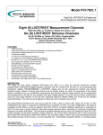
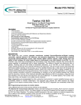
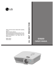
Model cPCI-75LD1 3U
Eight (8) LVDT/RVDT-to-Digital Channels
Eight (8) LVDT Measurement Channels
2-Wire or 3/4-Wire LVDT to Digital Converters
Auto-ranging; Optional On-Board Excitation
Commercial & Military Temperature Ranges
•
•
•
•
•
•
•
•
•
•
•
•
•
•
•
16-bit resolution
0.025% FS accuracy
Continuous background BIT testing with Excitation and Signal loss detection
Self-calibrating. Does not require removal for calibration
360 Hz to 10 kHz operation
Auto-ranging input between 2.0 and 28 Vrms
8 and 4-channel versions available
Optional programmable reference excitation
Transformer isolated
LATCH feature
Compensates for ±60° phase shift
I/O via front panel, P2 or both
Conducted cooled versions available
No adjustments or trimming required
Part number, S/N, Date Code, and Revision in non-volatile memory
DESCRIPTION:
This high-density intelligent DSP-based card incorporates up to eight (8) separate transformer isolated
programmable LVDT/RVDT-to-Digital tracking converters with extensive diagnostics, and optional programmable
excitation supply. Instead of buying cards that are set for specific inputs, the uniqueness of this design makes it
possible to order our standard card that auto ranges between 2.0 and 28 volts. Operating frequency between 400
Hz and 10 kHz can be specified (see part number). This card can be used for 4-wire , 3-wire or 2-wire LVDT
inputs. For 4-wire or 3-wire configurations the output is computed as A-B/A+B and is expressed as %FS. For 2wire configurations, the output is computed as A/B ( where A is the a-b signal of the LVDT and B is a constant
reference signal ) and is expressed as %FS This card uses a derived reference ratio-metric design approach that
is insensitive to magnitude, temperature, frequency and phase shift effects. The ratio-metric technique assures
that the output will change only when the LVDT position changes and will ignore excitation voltage variations. The
LATCH feature permits the user to read all channels at the same time. Reading will unlatch that channel. The
converters utilize a Type II servo loop processing technique that enables tracking, at full accuracy, up to the
specified rate. Intermediate transparent latches, on all data outputs, guarantee that current valid data is always
available for any channel without affecting the tracking performance of the converters. No interrupts or waiting
time are required. The optional on−board excitation is field programmable. To simplify logistics, Part Number,
S/N, Date Code, and Revision are stored in non-volatile memory locations.
This board incorporates major diagnostics that offer substantial improvements to system reliability because
the user is alerted to channel malfunction. This approach reduces bus traffic, because the Status Registers need
not be constantly polled. Three different tests (one on-line and two off-line) can be selected,
The D2 Test initiates automatic background BIT testing. Each channel is checked over the programmed signal
range to a measuring accuracy 0.1% FS, and each Signal and Excitation is monitored. Any failure triggers an
Interrupt (if enabled) and the results are available in registers. The testing is totally transparent to the user,
requires no external programming, has no effect on the standard operation of this card and can be enabled or
disabled via the bus.
North Atlantic Industries, Inc.
Apex Signal Division
110 Wilbur Place, Bohemia, NY 11716
631.567.1100/631.567.1823 (fax)
www.naii.com / e-mail: [email protected]
6/22/2005
Cage Code:OVGU1
75_LD1_A001_Rev_2.3
Page 1 of 8
The D3 Test, if enabled, starts an initiated BIT Test that disconnects all channels from the outside world and
connects them across an internal stimulus that generates and measures multiple voltages to a test accuracy of
0.1%FS. Board programmer may elect to initiate a D3 self-test immediately after power on during his initialization.
External excitation is not required. Any failure triggers an interrupt (if enabled) and results can be read from
registers. The testing requires no external programming and can be initiated or terminated at any time via the bus.
The D0 Test is used to check the card and the PCI interface. All channels are disconnected from the outside
world, allowing user to write any number of input positions to the card and then read the data from the interface.
External excitation is not required.
SPECIFICATIONS:
Number of channels:
Resolution:
Accuracy:
Bandwidth:
Input format:
Input voltage
Excitation voltage:
Input Impedance:
Frequency:
Phase shift:
Wrap around Self Test:
Interrupts:
Power:
Temperature, operating:
Storage temperature:
Size:
Weight:
REFERENCE SUPPLY:
Voltage:
Frequency:
Regulation:
Output power:
(applies to each channel)
4or 8 (see part number)
16-bit
0.025% FS
40 Hz. BW and tracking rate can easily be customized.
2, 3, or 4-wire LVDT or RVDT
Auto-ranging from 2.0 to 28 Vrms. Transformer isolated.
Not required for computation of output but should be connected to allow card to
check for excitation loss.
40 kΩ min. at 360 Hz
Specify between 360 Hz to 10 kHz, (See Part Number and Code Table)
Automatically compensates for phase shifts between the transducer excitation and
Output up to ±60° (3-wire units ignore phase shift)
Three powerful test methods are described in the Programming Instructions.
One Interrupt capability is implemented.
+ 5 VDC at 0.35 A
±12 VDC at 0.1 A without Excitation; 1.1 A for 5 VA Excitation Output
"C"=0°C to +70°C; "E"= -40°C to +85°C. (See part number)
-55°C to +105°C.
3U (3.94") height, 4HP (0.8") width. 100 mm x 20.3 mm x 160 mm deep
18 oz.
Optional. (See part number).
2-28Vrms programmable, or 115 Vrms fixed. Resolution 0.1 Vrms,
Accuracy ±2%
360 Hz to 10 kHz ±1% with 1 Hz resolution.
10% max. No load to full load.
5VA max. @ 40° min. inductive;
190mA RMS @ 2-28VAC, 45mA RMS @ 115VAC
Note: Power is reduced linearly as the Reference Voltage decreases (2-28VRMS):
i.e. Up 190mA can be delivered to a load for that respective reference voltage
range.
Principals of LVDT Operation: Typically the LVDT primary is excited by an ac source, causing a magnetic flux
to be generated within the transducer. Voltages are induced in the two secondaries, with the magnitude varying
with the position of the core. Usually, the secondaries are connected in series opposition, causing a net output
voltage of zero when the core is at the electrical center. When the core is displaced in either direction from center
the voltage increases linearly either in phase or out of phase with the excitation depending on the direction.
Interfacing the LVDT to the Converter: Two common connection methods are:
Primary as reference (two-wire system)
This method of connection converts the widest range of LVDT sensors and is the most sensitive to excitation
voltage variations, temperature and phase shift effects.
Derived reference (three/four-wire LVDT)
The LVDT is again excited from the primary side, but the converter reference is the sum of A + B that has
constant amplitude for changing core displacement. This system is insensitive to temperature effects, phase
shifts and oscillator instability and solves the identity (A-B)/(A+B)
North Atlantic Industries, Inc.
Apex Signal Division
110 Wilbur Place, Bohemia, NY 11716
631.567.1100/631.567.1823 (fax)
www.naii.com / e-mail: [email protected]
6/22/2005
Cage Code:OVGU1
75_LD1_A001_Rev_2.3
Page 2 of 8
LVDT Coil Voltage vs. Position
(IN-PHASE)
(USUAL LVDT CONFIGURATION)
10.0 V
Example uses
10Vrms output
Vb
5.0 V
Va
0.0 V
POSITION
-FS
O
Va+Vb=10V Va+Vb=10V
Va-Vb=-10V Va-Vb=0V
Va=0V
Va=5V
Vb=10V
Vb=5V
+FS
Va+Vb=10V
Va-Vb=10V
Va=10V
Vb=0V
Various LVDT configurations
OPTIONAL
ON BOARD
EXCITATION
OPTIONAL
ON BOARD
EXCITATION
4 Wire
3 Wire
A HI
A HI
a
a
A LO
A LO
B LO
Excitation IN
Excitation IN
B LO
b
b
B HI
B HI
POS = a - b
a+b
POS = a - b
a+b
Excitation Ref Hi
(Monitoring)
Excitation Ref Lo
Excitation Ref Hi
(Monitoring)
Excitation Ref Lo
OPTIONAL
ON BOARD
EXCITATION
2 Wire
A HI
a-b
A LO
a
Excitation IN
POS = a - b
Excit.
b
B HI
B LO
Excitation Ref Hi
(Monitoring)
Excitation Ref Lo
North Atlantic Industries, Inc.
Apex Signal Division
110 Wilbur Place, Bohemia, NY 11716
631.567.1100/631.567.1823 (fax)
www.naii.com / e-mail: [email protected]
6/22/2005
Cage Code:OVGU1
75_LD1_A001_Rev_2.3
Page 3 of 8
LVDT Connections:
For 3,4 Wire LVDT’s, connect A and B LVDT outputs to Signal A and B inputs. Excitation is not used, but should
be connected to allow card to monitor and report any excitation loss.
For 2 Wire LVDT’s, connect A-B output of LVDT to card “A” input and connect external excitation voltage to card
“B” input and to excitation input to allow card to monitor and report any excitation loss.
PROGRAMMING INSTRUCTIONS:
00
04
08
0C
10
14
18
1C
20
24
28
2C
30
34
38
3C
40
44
48
Ch.1 Data Hi
Ch.2 Data Hi
Ch.3 Data Hi
Ch.4 Data Hi
Ch.5 Data Hi
Ch.6 Data Hi
Ch.7 Data Hi
Ch.8 Data Hi
Velocity 1
Velocity 2
Velocity 3
Velocity 4
Velocity 5
Velocity 6
Velocity 7
Velocity 8
Scale Ch. 1
Scale Ch. 2
Scale Ch. 3
read
read
read
read
read
read
read
read
read
read
read
read
read
read
read
read
r/w
r/w
r/w
4C
50
54
58
5C
60
64
68
6C
70
74
78
7C
80
84
88
8C
90
94
Scale Ch.4
Scale Ch. 5
Scale Ch. 6
Scale Ch. 7
Scale Ch. 8
2 or 3,4 wire Input
Test angle
Test (D2) verify
Test Enable
Active channels
Interrupt Enable
Interrupt Status
Not Used
Status, Signal
Status, Reference
Status, Test
Latch
(A & B) res. Ch.1
(A & B) res. Ch.2
r/w
r/w
r/w
r/w
r/w
r/w
write
r/w
r/w
r/w
r/w
read
read
read
read
write
r/w
r/w
98
9C
A0
A4
A8
AC
B0
B4
B8
BC
C0
C4
C8
CC
D0
D4
D8
DC
E0
(A & B) res. Ch.3
(A & B) res. Ch.4
(A & B) res. Ch.5
(A & B) res. Ch.6
(A & B) res. Ch.7
(A & B) res. Ch.8
Velocity scale Ch.1
Velocity scale Ch.2
Velocity scale Ch.3
Velocity scale Ch.4
Velocity scale Ch.5
Velocity scale Ch.6
Velocity scale Ch.7
Velocity scale Ch.8
Magnitude (A+B) Ch.1
Magnitude (A+B) Ch.2
Magnitude (A+B) Ch.3
Magnitude (A+B) Ch.4
Magnitude (A+B) Ch.5
r/w
r/w
r/w
r/w
r/w
r/w
r/w
r/w
r/w
r/w
r/w
r/w
r/w
r/w
read
read
read
read
read
E4
E8
EC
F0
F4
F8
FC
100
104
108
10C
110
114
118
11C
120
124
128
12C
Magnitude (A+B) Ch.6
Magnitude (A+B) Ch.7
Magnitude (A+B) Ch.8
Not Used
Not Used
Not Used
Not Used
Freq. (Ref. Supply)
Eo (Ref. Supply)
Watchdog timer
Soft reset
Part Number
Serial Number
Date code
PC Board rev.
Software rev.
Interface FPGA rev.
FPGA rev.
Board Ready
read
read
read
r/w
r/w
r/w
write
read
read
read
read
read
read
read
read
REGISTER BIT MAP
Latch Outputs
Test Enable
Active channels
Status, Test
Status, Signal
Status, Excitation
2 or 3,4 wire Input
Interrupt
(A&B) resolution
D15
X
X
X
X
X
X
X
X
0
D14
X
X
X
X
X
X
X
X
X
D13
X
X
X
X
X
X
X
X
X
D12
X
X
X
X
X
X
X
X
X
D11
X
X
X
X
X
X
X
X
X
D10
X
X
X
X
X
X
X
X
X
D9
X
X
X
X
X
X
X
X
X
D8
X
X
X
X
X
X
X
X
X
D7
X
X
Ch.8
Ch.8
Ch.8
Ch.8
Ch.8
X
X
D6
X
X
Ch.7
Ch.7
Ch.7
Ch.7
Ch.7
X
X
D5
X
X
Ch.6
Ch.6
Ch.6
Ch.6
Ch.6
X
X
TABLE 3
Note 1 –Values are rounded off.
D4
D3
X
X
X
D3
Ch.5
Ch.4
Ch.5
Ch.4
Ch.5
Ch.4
Ch.5
Ch.4
Ch.5
Ch.4
X
#4
X
X
16 bit
15 bit
14 bit
13 bit
12 bit
Encoder outputs
INTERRUPT ENABLE & STATUS REGISTERS
#1 = S/D Signal Loss
#2 = S/D Reference Loss
D2
X
D2
Ch.3
Ch.3
Ch.3
Ch.3
Ch.3
X
X
0
0
0
0
1
D1
1
X
Ch.2
Ch.2
Ch.2
Ch.2
Ch.2
#2
D1
0
0
1
1
0
D0
X
D0
Ch.1
Ch.1
Ch.1
Ch.1
Ch.1
#1
D0
0
1
0
1
0
↑
#4 = S/D Test Accuracy Error (BIT)
Immediately following a Power-On or System Reset, it is suggested a D3 test be implemented if a complete self
test is desired.
Enter Active Channels: Set the bit, corresponding to each channel to be monitored during BIT testing, in the
Active Channel Register. “1”=active; “0”=not used. Omitting this step will produce false alarms because unused
channels will set faults.
Optional Reference/Excitation Supply: For excitation frequency, write a 16-bit word (Ex: 400 Hz =
110010000) to the Internal Excitation Frequency Register. For voltage, write an 16-bit word (Ex: 26.1Vrms
=100000101) with LSB=0.1Vrms, to Internal Excitation Eo Register. It is recommended that user program the
required frequency before setting the output voltage.
North Atlantic Industries, Inc.
Apex Signal Division
110 Wilbur Place, Bohemia, NY 11716
631.567.1100/631.567.1823 (fax)
www.naii.com / e-mail: [email protected]
6/22/2005
Cage Code:OVGU1
75_LD1_A001_Rev_2.3
Page 4 of 8
Interrupt Registers: Interrupts can be enabled to relay specific problems/failures detected by the card. The
problem/failures that generate these interrupts are:
LVDT Signal Loss, LVDT Reference Loss, LVDT Test Accuracy Error (BIT),
Each external interrupt can be enabled individually. This is accomplished by writing a “1” to the bit corresponding
to desired interrupts to the Interrupt Enable Register and a “0” to disable those interrupts not used. Refer to
Register Bit Map.
Interrupt Status Registers: When an interrupt is initiated via a problem/failure, the Interrupt Status Register
can be interrogated by a read to identify, which interrupt occurred. See Register Bit Map. Register is latched when
interrupt is generated and unlatched when read.
Note: This register is typically read and cleared by the device driver. Subsequent readings of this register will
give clear status
Selecting 2 or 3,4 Wire operation: Program the corresponding bit for the appropriate channel in the 2-3/4
Wire Register. Logic 1 = 2 wire; Logic 0 = 3 or 4 wire.
Data Format:
For 4-wire or 3-wire inputs, the output data is A-B/A+B and represents %FS. Format is two's complement.
Maximum positive excursion is 32767 (7FFFh), 0 = 0, and maximum negative excursion is -32768 (8000h).
For 2-wire input, the output data is A-B/Excitation and represents %FS. Format is two's complement. Maximum
positive excursion is 32767 (7FFFh), 0 = 0, and maximum negative excursion is -32768 (8000h).
Programming Scale Registers
The 4-wire or 3-wire LVDT has two output voltages referred to as A and B. When connected to the A and B
Signal inputs, no scaling is required because the inputs are auto-ranging, however the corresponding Scale
Register can be used to scale the output code.
Default settings for the Scale Registers are set to 65535 (FFFFh) which results in a full-scale output reading for
full travel of the LVDT. A full-scale output reading for less than full travel of the LVDT can be obtained by writing
a scale value to the corresponding Scale Register. For example, writing 32768 (8000h) to Scale Ch. 1 Register
will result in channel 1 having a full-scale output reading for one-half travel of the LVDT.
For 2-wire input, the default settings for the Scale Registers are 65535 (FFFFh), which result in a full-scale output
reading for full travel of the LVDT for TR = 1 (transformation ratio). To achieve full output readings for TR < 1, a
scale factor (SF) should be programmed into the corresponding Scale Register. This is calculated from the
equation:
SF =65535 (FFFFh) x TR
The calculated SF value is written to the corresponding Scale Register.
Read (A+B): Read binary number from the (A+B) Magnitude Register and multiply by 0.01 Volt. Only valid for 3
or 4 wire configurations.
Velocity Scale Factor: To scale the Max Velocity word for 150 Strokes / Second (SpS), set Velocity Scale
Factor = 4095 in HEX (max velocity word of 7FFFh being max. CW rotation, and 8000h being max. CCW
rotation).
Scaling effects only the Velocity output word and not the dynamic performance.
Ex:
To get max. velocity word @ 150 SPS: 4095(150/150) = 4095 (0FFFh) This is also the Factory setting.
To get max. velocity word @ 50 SPS. 4095(150/50) = 12,285 (2FFDh)
To get max. velocity word @ 9.375 SPS.4095(150/9.375) = 65,520 (FFF0h) This is also the lowest
setting.
Velocity Output: Read Velocity registers of each channel as a 2’s complement word, with 7FFFh being max.
CW rotation, and 8000h being max. CCW rotation.
When max. velocity is set to 150 SpS, an actual speed of 10 SpS CW would be read as 0888h.
When max. velocity is set to 150 SpS, an actual speed of 10 SpS CCW would be read as F778h.
When max. velocity is set to 50 SpS, an actual speed of 10 SpS CW would be read as 1999h.
When max. velocity is set to 50 SpS, an actual speed of 10 SpS CCW would be read as E667h.
To convert a velocity word, for example E667h, into rps: If max. velocity set to 50 SpS, then
SpS = 50 x E667h / 32,768 = 50 x -6,553 / 32,768 = -10 SpS
Latch: All channels may be latched by writing a “1” to D1 in the Latch Register. Reading a particular channel
will disengage the latch for that channel. Writing a 0 to this register will disengage latch on all channels.
North Atlantic Industries, Inc.
Apex Signal Division
110 Wilbur Place, Bohemia, NY 11716
631.567.1100/631.567.1823 (fax)
www.naii.com / e-mail: [email protected]
6/22/2005
Cage Code:OVGU1
75_LD1_A001_Rev_2.3
Page 5 of 8
D2 Test Enable: Writing a “1” to the D2 bit of the Test Enable Register initiates automatic background BIT
testing. Each channel is checked over the programmed Signal range to a measuring accuracy 0.1%FS. An
Interrupt will be set to indicate an accuracy problem. A “0” deactivates this test The testing is totally
transparent to the user, requires no external programming, has no effect on the standard operation of this
card and can be enabled or disabled via the bus. The results are available in Test Status Registers. The
card will write 55h to the Test D2 Verify Register when D2 Test is enabled. User can periodically clear to 00h
and then read the Test D2 Verify Register again, after 30 seconds, to verify that background BIT testing is
activated.
In addition, each Signal and Excitation input is continually monitored. Any failure triggers an Interrupt (if enabled)
and the results are available in the Signal and Excitation Status Registers.
Status, Test: Check the corresponding bit of the Test Status Register, for status of BIT testing for each active
channel. A ”1” =Accuracy OK; “0” = failed. Channels that are inactive are also set to “0”. (Test cycle takes 45
seconds for accuracy error). Any Test status failure, transient or intermittent will latch the Test Status Register.
Reading will unlatch register.
Status, Excitation: Check the channel’s corresponding bit of the Excitation Status Register, for status of the
Excitation input for each active channel. A ”1” = Excitation. ON, “0” = Excitation. loss. Channels that are inactive
are also set to “0”. (Excitation loss is detected after 2 seconds). Excitation monitoring is disabled during D3 or D0
Test. Any Excitation status failure, transient or intermittent will latch the Excitation Status Register. Reading will
unlatch register.
Status, Signal: Check the channel’s corresponding bit of the Signal Status Register, for status of the input
signals for each active channel. A "1" = Signal ON, “0” = Signal loss. Channels that are inactive are also set to
“0”. (Signal loss is detected after 2 seconds). Any Signal status failure, transient or intermittent will latch the
Signal Status Register. Reading will unlatch register.
D3 Test Enable: A complete Self-Test, is enabled, when writing a “1” to D3 in the Test Enable Register. This
starts an initiated BIT test that disconnects all channels from the outside world and connects them across an
internal stimulus that generates multiple test voltages that are measured to a test accuracy of 0.1%FS. Test cycle
takes about 10 seconds and results can be read from the Test Status Register when D3 changes from “1” to “0”.
External excitation is not required. An Interrupt, if enabled will be generated if a BIT failure is detected (See
Interrupt Register). Testing requires no external programming and can be terminated by writing “0” to D3 of the
Test Enable Register.
Signal and Excitation monitoring is disabled during D3 test.
D0 Test Enable: Checks the card and interface. Writing a “1” to D0 in the Test Enable Register disconnects all
channels from the outside world, allowing user to write any number of input positions to the card in the LVDT/D
Test Position Register and then reads the data from the PCI bus (allow 50 ms before reading). External
excitation is not required.
Signal and Excitation monitoring is disabled during D0 test.
(A&B) Encoder Resolution: Enter required resolution, for each channel, per above table (Register Bit Map).
Can be changed on the fly. Encoder outputs are optional, see part ordering information. Default is 12 bit encoder
output.
Watchdog Timer: This feature monitors the Watchdog Timer Register. When it detects that a code has been
received, that code will be inverted within 100 µSec. The inverted code stays in the register until replaced by a
new code. User, after 100 µSec, should look for the inverted code to confirm that the processor is operating.
Soft Reset: Write an integer “1” to Soft Reset Register, then clear to 0 before 50ms elapses. CAUTION:
Register is level sensitive and for proper card operation, the logic level “1”, or pulsewidth, must be <=
50ms. Considering minimum and maximum, 1 μs < pulsewidth <= 50ms. Processor reboots in about 400 ms,
after which calibration procedures begin. This function is equivalent to a power-on reset.
Part Number: Read as a 16-bit binary word from the Part Number Register. A unique 16 bit code is assigned to
each model number.
Serial Number: Read as a 16 bit binary word from the Serial Number Register. This is the serial number of that
particular board.
Date Code: Read as decimal number from the Date Code Register. Four digits represent YYWW (Year, Year,
Week, Week).
North Atlantic Industries, Inc.
Apex Signal Division
110 Wilbur Place, Bohemia, NY 11716
631.567.1100/631.567.1823 (fax)
www.naii.com / e-mail: [email protected]
6/22/2005
Cage Code:OVGU1
75_LD1_A001_Rev_2.3
Page 6 of 8
Rev Levels: There are a total of 6 Revision Level Registers, which are listed below. Each register is defined as
16 bits. The integer value of that particular register corresponds to the actual revision.
Rev level PCB
Rev level DSP
Rev level FPGA
Rev level Interface FPGA
Board Ready: When board initialization is completed (& auto-cal for A/D modules), after as much as 10
seconds, the board is ready for access and the Board Ready register is set to “AA55”.
Software - PCI Programming
This section provides programmers the information needed for developing drivers other than those supplied.
The following information resides in the PCI configuration registers:
Device ID
= 7531h
Vendor ID
= 15ACh
Rev
= 01h
Subsystem ID
= 000115ACh
Base Address
= Assigned by the PCI BIOS. Interrogate the PCI BIOS for this information.
Required Address space
= 1K for each card.
Front panel Connector:
DD-50P, Mate: DD-50S (not supplied)
Pin
25
8
9
24
7
23
Ch. 1
A Lo
B Hi
A Hi
B Lo
RHi
RLo
Pin
22
5
6
21
20
4
Ch. 2
A Lo
B Hi
A Hi
B Lo
RHi
RLo
Pin
2
19
3
18
35
36
Ch. 3 Pin Ch. 4 Pin Ch. 5 Pin Ch. 6 Pin Ch. 7 Pin Ch. 8 Pin Ref. Output
A Lo
42 A Lo
43 A Lo
45 A Lo
31 A Lo
49 A Lo
1 Ref Hi Out
B Hi
37 B Hi
26 B Hi
28 B Hi
30 B Hi
32 B Hi
34 Ref Lo Out
A Hi
41 A Hi
27 A Hi
29 A Hi
47 A Hi
33 A Hi
B Lo
38 B Lo
10 B Lo
12 B Lo
14 B Lo
16 B Lo
RHi
39 RHi
11 RHi
13 RHi
15 RHi
17 RHi
RLo
40 RLo
44 RLo
46 RLo
48 RLo
50 RLo
Rear panel J2 connector
Pin
D20
E21
E20
D21
E19
D19
Ch. 1
A Lo
B Hi
A Hi
B Lo
RHi
RLo
Pin
D17
E18
E17
D18
C19
B19
Ch. 2
A Lo
B Hi
A Hi
B Lo
RHi
RLo
Pin
D15
E16
E15
D16
E14
D14
Ch. 3
A Lo
B Hi
A Hi
B Lo
RHi
RLo
Pin
D12
E13
E12
D13
C14
B14
Ch. 4 Pin Ch. 5 Pin Ch. 6 Pin Ch. 7
A Lo
D2 A Lo
D5 A Lo
D7 A Lo
B Hi
E3 B Hi
E6 B Hi
E8 B Hi
A Hi
E2 A Hi
E5 A Hi
E7 A Hi
B Lo
D3 B Lo
D6 B Lo
D8 B Lo
RHi
E4 RHi
C4 RHi
E9 RHi
RLo
D4 RLo
B4 RLo
D9 RLo
Pin
D10
E11
E10
D11
C9
B9
Ch. 8 Pin Ref. output
A Lo
E22 Ref Hi Out
B Hi
D22 Ref Lo Out
A Hi
B Lo
RHi
RLo
Do not connect to any undesignated pins
North Atlantic Industries, Inc.
Apex Signal Division
110 Wilbur Place, Bohemia, NY 11716
631.567.1100/631.567.1823 (fax)
www.naii.com / e-mail: [email protected]
6/22/2005
Cage Code:OVGU1
75_LD1_A001_Rev_2.3
Page 7 of 8
Code Table
Code
01
02
03
04
05
06
Frequency (Hz)
400
2.8K - 3.2K
2K
2.69K
2.5kHz
7kHz
Notes
See code list addendum for descriptions of code 50 and above
PART NUMBER DESIGNATION
75LD1- XX X X X X - XX
TOTAL NUMBER OF CHANNELS
04 = 4 Channels
08 = 8 Channels
CODE (See Code Table)
ENCODER/COMMUTATION
- = Without Encoder/Commutation option
E = With Encoder/Commutation option
ENVIRONMENTAL
C = 0°C to +70°C
E = -40°C to +85°C
H = E With Removable Conformal Coating
K = C With Removable Conformal Coating
OPTIONAL REFERENCE SELECTION
0 = No “On Board Reference”
A = 2-28 VRMS output
contact factory for other temperature requirements
EXCITATION CONNECTIONS
1 = One Common Excitation input tied
to the Excitation Supply
2 = Individual Excitation Inputs
MECHANICAL
F = Front Panel I/O only
B = Front Panel I/O and J2 I/O
P = J2 I/O only
W= P with Wedgelocks (cPCI only, not PXI)
Note: J2 connections can not be used for
Analog signals in a PXI chassis. Analog
Outputs must be via the front panel I/O only
North Atlantic Industries, Inc.
Apex Signal Division
110 Wilbur Place, Bohemia, NY 11716
631.567.1100/631.567.1823 (fax)
www.naii.com / e-mail: [email protected]
C = 115 VRMS fixed output
6/22/2005
Cage Code:OVGU1
75_LD1_A001_Rev_2.3
Page 8 of 8
Revision Page
Revision
Description of Change
1.2
Initial Release
1.3
Engineer
Date
GS
05/01/02
Corrected Header for 8 (not 16) channels
GS
06/05/02
1.4
For proper Soft Reset operation, 1μ < pulsewidth <=50ms.
GS
6/27/02
1.5
Removed 2-13.5 volt reference option (from spec, and PN)
GS
6/28/02
8/28/02
9/5/02
1.6
Adds Board Ready
GS
1.7
Removed all references to Save and Post. Update Graphic Va-Vb = -10, first column.
GS
1.8
Edited D3 test to imply POST feature
GS
9/6/02
1.9
Corrected LDVT -> to LVDT in diagram title.
GS
9/19/02
2.0
Conducted cooled versions available
GS
7/7/4
2.1
Removes Wedgelock option from PN. Conduction cooled version is NOT available
GS
4/19/5
2.2
Adds Wedgelock option back to PN. Conduction cooler version is available.
GS
6/22/5
New Address
KL
04/25/07
2.3
North Atlantic Industries, Inc.
Apex Signal Division
110 Wilbur Place, Bohemia, NY 11716
631.567.1100/631.567.1823 (fax)
www.naii.com / e-mail: [email protected]
6/22/2005
Cage Code:OVGU1
75_LD1_A001_Rev_2.3
Page 9 of 8