1
SSD Parvex SAS
8, avenue du Lac - B.P. 249
F-21007 Dijon Cedex
www.SSDdrives.com
DIGIVEX Multi Drive
DIGITAL SERVOAMPLIFIER
User and commissioning manual
PVD 3464 GB – 04/2004
PRODUCT RANGE
1-
« BRUSHLESS » SERVODRIVES
TORQUE OR POWER
RANGES
•
•
•
2-
BRUSHLESS SERVOMOTORS, LOW INERTIA, WITH RESOLVER
Very high torque/inertia ratio (high dynamic performance machinery):
⇒ NX -HX - HXA
⇒ NX - LX
High rotor inertia for better inertia load matching:
⇒ HS - LS
Varied geometrical choice :
⇒ short motors range HS - LS
⇒ or small diameter motors : HD, LD
Voltages to suit different mains supplies :
⇒ 230V
three-phase for «série L - NX»
⇒ 400V, 460V three-phase for «série H - NX»
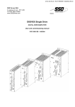
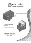
"DIGIVEX Drive" DIGITAL SERVOAMPLIFIERS
⇒ SINGLE-AXIS
DSD
⇒ COMPACT SINGLE-AXIS
DµD, DLD
⇒ POWER SINGLE-AXIS
DPD
⇒ MULTIPLE-AXIS
DMD
"PARVEX MOTION EXPLORER" ADJUSTING SOFTWARE
1 to 320 N.m
0,45 to 64 N.m
3,3 to 31 N.m
3,3 to 31 N.m
9 to 100 N.m
SPINDLE DRIVES
•
•
3-
SPINDLE SYNCHRONOUS MOTORS
⇒ "HV" COMPACT SERIES
⇒ "HW" ELECTROSPINDLE,frameless, water-cooled motor
From 5 to 110 kW
up to 60,000 rpm
"DIGIVEX" DIGITAL SERVOAMPLIFIERS
DC SERVODRIVES
•
•
•
4-
"AXEM", "RS" SERIES SERVOMOTORS
"RTS" SERVOAMPLIFIERS
"RTE" SERVOAMPLIFIERS for DC motors + resolver giving position
measurement
0.08 to 13 N.m
SPECIAL ADAPTATION SERVODRIVES
•
•
5-
"EX" SERVOMOTORS for explosive atmosphere
"AXL" COMPACT SERIES SERVOREDUCERS
POSITIONING SYSTEMS
•
•
•
•
Numerical Controls « CYBER 4000 » 1 to 4 axes
"CYBER 2000" NC 1 to 2 axes
VARIABLE SPEED DRIVE - POSITIONER
⇒ SINGLE-AXIS
DSM
⇒ POWER SINGLE-AXIS
DPM
⇒ MULTIPLE-AXIS
DMM
ADJUSTMENT AND PROGRAMMING SOFTWARE PARVEX MOTION EXPLORER
5 to 700 N.m
Servoamplifier DIGIVEX Multi Drive
CONTENTS
SAFETY...........................................................................................................................................................5
1.
GENERAL
7
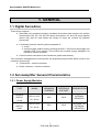
1.1 Digital Servodrive
1.2 Servoamplifier General Characteristics
1.2.1
Power Supply Modules
1.2.2
Servoamplifier Modules
1.2.3
Possible Combinations
1.3 Rack, general
1.4 DIGIVEX Power Supply
1.4.1
Presentation
1.4.2
Block Diagram
1.4.3
Braking Energy Dissipation
1.5 DIGIVEX Drive SERVOAMPLIFIER
1.5.1
Presentation
1.5.2
General Characteristics
1.5.2.1 Functions
1.5.2.2 Electrical Characteristics
1.6 Compliance with Standards
2. SPACE REQUIREMENTS, ASSEMBLY, LABELLING,
CODES
2.1 Dimensions and mounting
2.1.1
Rack and Power Supply
2.1.2
DIGIVEX Drive
2.2 Labels, Codes
2.2.1
Racks
2.2.2
Power Supply
2.2.3
DIGIVEX Drive
3.
7
7
7
8
8
8
9
9
10
12
15
15
15
15
16
18
19
19
19
22
22
22
23
24
ELECTRICAL CONNECTIONS
3.1 General Wiring Requirements
3.1.1
Electromagnetic Compatibility
3.1.2
DIGIVEX DRIVE SUB-D Plug, general
3.2 Typical Connection Diagram
3.2.1
Surge Suppressor
3.3 Power Supply connection
3.3.1
Front panel terminal blocks
3.3.2
Terminal block characteristics
3.3.3
Power component dimensions
3.3.4
Connection to mains
1
PVD 3464 GB 04/2004
25
25
25
26
27
30
31
31
32
32
33
Servoamplifier DIGIVEX Multi Drive
3.3.5
Low-Level and Auxiliary Supply
34
3.3.6
External Energy Dissipation Resistor
35
3.3.7
Control signal connection (terminal Blocks X2 and X3)
35
3.3.8
Terminal Block X1 "Brake Supply"
38
3.4 DIGIVEX Drive connection
38
3.4.1
Front plate terminals
38
3.4.2
Terminal blocks and sockets characteristics
40
3.4.3
DIGIVEX Drive Servomotor connection
40
3.4.3.1 "POWER" Cable Definition
40
3.4.3.2 Guidelines for use of inductors and resistors for long cables between the motor and
drive
42
3.4.3.3 Connection to motor (power, brake, thermal protector and ventilation)
42
3.4.3.4 Resolver Connection
49
3.4.4
"Input/Output" SUB-D Plug
52
3.4.4.1 Inputs/Outputs description
52
3.4.4.2 Input/Output Cable (Terminal Block X2 Inputs/Outputs)
56
3.4.5
SUB-D Plug
58
3.4.5.1 Definition
58
3.4.5.2 RS 232 cable
58
3.5 Accessories
58
3.5.1
Mains filter
58
3.5.2
External energy dissipation resistors
60
3.5.3
Tool
60
3.5.4
Cables
60
3.5.5
Inductors for long cable lengths with axis motor
61
4.
PARAMETER FUNCTION AND ADJUSTMENT
4.1 DIGIVEX Power Supply
4.1.1
Straps positions
4.1.2
Initialization Sequence
4.2 DIGIVEX Drive
4.2.1
Functions
4.2.1.1 Block Diagram
4.2.1.2 Logic Input Forcing
4.2.1.3 Stimulus/Oscilloscope Function
4.2.1.4 Logic outputs
4.2.1.5 Brake Action
4.2.1.6 Emergency Stop (speed loop mode only)
4.2.2
Servocontrol and Adjustment Parameters
4.2.2.1 List of Parameters
4.2.2.2 Regulation Selection: Current, Proportional, Pl, Pl≤
4.2.2.3 Integration Stop
4.2.2.4 Speed Scaling
2
PVD 3464 GB 04/2004
64
64
64
66
66
66
66
69
69
69
69
70
70
70
71
73
73
Servoamplifier DIGIVEX Multi Drive
4.2.2.5 Filtering Frequency
4.2.2.6 Predictors
4.2.3
Entering Parameters / personnalization board/change
4.2.4
Servocontrol Parameter Setting
4.2.4.1 Overview of Settings
4.2.4.2 Parameters setting Tools
4.2.4.3 Parameter Access Condition
4.2.4.4 Motor Selection and Parameter Entry via DIGIVEX PC Software
4.2.4.5 Loop Parameter Adjustment Speed Regulation Mode
4.2.4.6 Predictor Adjustment
4.2.4.7 Parameter Adjustment in Current Regulation Mode
4.2.4.8 Other Parameters
5.
74
74
76
77
77
78
80
81
81
85
89
89
STARTING UP - DETECTING CAUSES OF STOPPAGE
90
5.1 Start Up Sequence
5.1.1
Prior Checks
5.1.2
First Time Starting with DIGIVEX PC Software or the terminal
5.1.3
Start up or Modification with the Display / Parameter Setting Terminal / Parameters
transfer 92
5.2 Detecting causes of stoppage
5.2.1
DIGIVEX Power Supply
5.2.2
DIGIVEX Drive
5.2.2.1 Display
5.2.2.2 Drive Fault Processing
5.2.2.3 Current Monitoring
5.2.2.4 Temperature Monitoring
5.2.2.5 Miscellaneous Monitoring
5.2.2.6 Fault and Diagnostic Summary Chart
5.2.2.7 Corrective actions
5.2.2.8 7-segment display (SS 6611 mounted)
6.
OPTIONS
90
90
91
92
92
93
93
93
94
95
95
96
97
97
98
6.1 Possible associations
6.2 Encoder Emulation Card Option (SC 6631)
6.2.1
Resolution and Zero Signal Position Programming
6.2.2
Electrical Characteristics
6.2.3
SUB-D Plug
6.2.4
Encoder Emulation Cable (ENCODER terminal block X3)
DIGIVEX SERVO-AMPLIFIER
98
98
98
99
101
101
103
PLUGS AND CABLES FOR DIGIVEX AND HX, HS, HD 104
3
PVD 3464 GB 04/2004
Servoamplifier DIGIVEX Multi Drive
Characteristics and dimensions subject to change without notice.
YOUR LOCAL CORRESPONDENT
SSD Parvex SAS
8 Avenue du Lac / B.P 249 / F-21007 Dijon Cedex
Tél. : +33 (0)3 80 42 41 40 / Fax : +33 (0)3 80 42 41 23
www.SSDdrives.com
4
PVD 3464 GB 04/2004
Servoamplifier DIGIVEX Multi Drive
SAFETY
Servodrives present two main types of hazard :
- Electrical hazard
Servoamplifiers may contain non-insulated live AC or DC
components. Users are advised to guard against access
to live parts before installing the equipment.
Even after the electrical panel is de-energized, voltages
may be present for more than a minute, until the power
capacitors have had time to discharge.
Specific features of the installation need to be studied to
prevent any accidental contact with live components :
- Connector lug protection ;
- Correctly fitted protection and earthing features ;
- Workplace insulation
(enclosure insulation humidity, etc.).
General recommendations :
• Check the bonding circuit;
• Lock the electrical cabinets;
• Use standardised equipment.
- Mechanical hazard
Servomotors can accelerate in milliseconds. Moving parts
must be screened off to prevent operators coming into
contact with them. The working procedure must allow the
operator to keep well clear of the danger area.
All assembly and commissioning work must be done by
qualified personnel who are familiar with the safety
regulations (e.g. VDE 0105 or accreditation C18510).
5
PVD 3464 GB 04/2004
Servoamplifier DIGIVEX Multi Drive
Upon delivery
All servoamplifiers are thoroughly inspected during manufacture and tested at length before
shipment.
•
•
Unpack the servoamplifier carefully and check it is in good condition.
Also check that data on the manufacturer's plate comries with data on the order
acknowledgement.
If equipment has been damaged during transport, the addressee must file a complaint with the
carrier by recorded delivery mail within 24 hours.
Caution :
The packaging may contain essential documents or accessories, in particular :
• User Manual,
• Connectors.
Storage
Until installed, the servoamplifier must be stored in a dry place safe from sudden temperature
changes so condensation cannot form.
Special instructions for setting up the equipment
CAUTION
For this equipment to work correctly and safely it must be
transported, stored, installed and assembled in accordance with
this manual and must receive thorough care and attention..
Failure to comply with these safety instructions may lead to
serious injury or damage.
The cards contain components that are sensitive to electrostatic
discharges. Before touching a card you must get rid of the static
electricity on your body. The simplest way to do this is to touch a
conductive object that is connected to earth (e.g. bare metal parts
of equipment cabinets or earth pins of plugs).
6
PVD 3464 GB 04/2004
Servoamplifier DIGIVEX Multi Drive
1. GENERAL
1.1 Digital Servodrive
These drives comprise :
• Sinusoidal emf, permanent magnet, brushless servomotors with resolvers for position
measurement NX, HX, HS and HD range servomotors. HV and HW range spindel
motors may also be used (these two ranges of motor are covered by separate
documents).
•
•
A multi-axis electronic control system composed of :
♦ A rack ;
♦ A power supply module directly receiving the 400 V / 50-60 Hz mains supply and
providing 550 V bus voltage. This module also controls energy dissipation via
internal or external resistors.
Control modules connected to the servomotor (power and resolver).
Two connection arrangements for servomotors are proposed (except HX300 which comes in the
connector version only):
• Terminal box + resolver connector.
• Power connector + resolver connector.
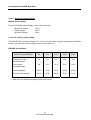
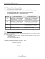
1.2 Servoamplifier General Characteristics
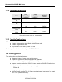
1.2.1 Power Supply Modules
TYPE
MAINS
DIGIVEX
400 V+/-10%
SUPPLY
12 kW
DIGIVEX
SUPPLY
25kW
50 - 60 Hz
400 V+/-10%
50 - 60 Hz
MEAN BUS
CURRENT
RATED BUS
VOLTAGE
REGENERATION
25 A
540 V
INTERNAL
RESISTOR
50 A
540 V
INTERNAL OR
EXTERNAL
RESISTOR
7
PVD 3464 GB 04/2004
Servoamplifier DIGIVEX Multi Drive
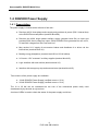
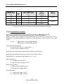
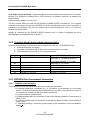
1.2.2 Servoamplifier Modules
TYPE
DIGIVEX Drive
2/4
DIGIVEX Drive
4/8
DIGIVEX Drive
8/16
DIGIVEX Drive
16/32
DIGIVEX Drive
32/64
PEAK
PERMANENT
CURRENT
* PEAK
PULSE
CURRENT
MODULE
FORMAT
2A
4A
SINGLE
4A
8A
SINGLE
8A
16 A
SINGLE
16 A
32 A
DOUBLE
32 A
64 A
TRIPLE
* Peak pulse current up to 2 s, non repetitive
1.2.3 Possible Combinations
Different versions of several rack models are available :
• 6-location single module racks (19 inch, double Europe rack).
• 3-location single module racks.
• Single module 13-slot racks (19-inch 15U rack).
Rack composition is further restricted by the POWER SUPPLY format.
1.3 Rack, general
The rack provides the following functions :
• Mechanical support of power supply and drive cards.
• Support for regeneration resistors and power bus capacitors.
• Power transfer from supply to drive (550 V power bus).
• Low-level supply transfer from DIGIVEX Power Supply to DIGIVEX Drive (low-level
bus).
• Logic signal transfer between drive and power supply :
♦ Drive OK
♦ Reset
• Emergency stop control
• 24V brake supply transfer. The 24V filtered-regulated supply is not part of our supply,
see § 3.4.3.3 (brake connection).
8
PVD 3464 GB 04/2004
Servoamplifier DIGIVEX Multi Drive
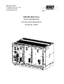
1.4 DIGIVEX Power Supply
1.4.1 Presentation
The power supply is located at the left side of the rack :
•
Receives 400 V three-phase mains supply and provides dc power (550 V internal bus)
to the DIGIVEX servoamplifiers (terminal block B2).
•
Receives the 400V single phase auxiliary supply (terminal block B1) as input and
provides 550V direct voltage as output. Each DIGIVEX Drive generates its own ±15V,
5V and 24V voltages from this "low level bus".
•
May receive 24 V supply for servomotor brakes and distributes it to drives via the
internal bus (terminal block X1).
•
Braking energy dissipation (terminal block B3 on 25 kW calibre).
•
24 V and ± 15V "customer" auxiliary supplies (terminal block X3).
•
Logic interface with main switch (terminal block X2).
•
Interface with emergency stop and external reset (terminal block X3).
Two versions of the power supply are available :
•
•
12 kW DIGIVEX Power Supply (rectified current = 25 A)
25 kW DIGIVEX Power Supply (rectified current = 50 A)
The 12 or 25 kW can be considered as the sum of the mechanical power really used
simultaneously by the axis at a given time.
A series of LEDs is used to check the status of the power supply and drives
9
PVD 3464 GB 04/2004
Servoamplifier DIGIVEX Multi Drive
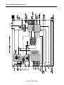
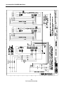
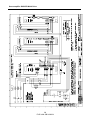
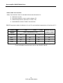
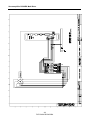
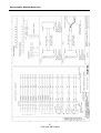
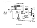
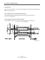
1.4.2 Block Diagram
See following pages. The left-hand side shows inputs that can be accessed by plug-in terminal
blocks on the front panel. The right-hand side shows card end connection to the rack mother card.
For the power section :
• Hexaphase diode rectification.
• Current limitation resistor in diodes at start up (short circuited when bus voltage is
adequate).
• Control of energy regeneration via resistor (top right), internal only for 12 kW supply
(resistor at rear of mother card), internal or external for 25 kW supply.
• Control of insufficient or excessive mains voltage and control of bus voltage.
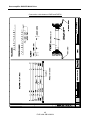
The low-level supply unit (auxiliary) comprises :
• Single-phase rectification, the "auxiliary bus" from which each drive derives the voltage
required to power its regulation card (chopping and isolation transformer for drive
cards).
• Auxiliary supplies :
♦ 24 V common to "customer" terminal block and rack fans.
♦ ± 15 V common to "customer" terminal block and internal supply regulation.
• 24 V brake which simply passes through the power supply (at bottom of block
diagram).
• Terminal block logic inputs/outputs, including on left-hand side of block diagram :
Reset - Emergency Stop - Ready - OK
Logic links with drives:
Supply :
• Sends initialization signal to drives (Init).
• Sends reset signal.
• Sends emergency stop signal.
• Receives logic signal (Drive OK) from each drive possibly tripping "OK relay".
• Receives a signal « Axis present », if at least 1 axis is located in the rack.
"Protection Management" block
• Logic block carrying out protection sequences (locking drives, controlling Ready and
OK relays) and ordering LEDs to be energized on the front panel.
10
PVD 3464 GB 04/2004
Servoamplifier DIGIVEX Multi Drive
CHOPPER
SUPPLY
11
PVD 3464 GB 04/2004
Servoamplifier DIGIVEX Multi Drive
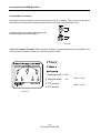
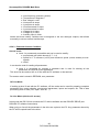
1.4.3 Braking Energy Dissipation
Braking energy is dissipated by a rack-mounted resistor for the 12 kW power supply, or rackmounted or external resistor for the 25 kW power supply.
Regeneration is controlled on the basis of two voltage limits measured across the power bus :
• Resistor cuts in at U = 700 V.
• Resistor cuts out at U = 690 V.
Upon energising the system tests the value of the current through the braking resistor. It should be
10 A < I < 70 A. This means either no resistance (break) or a short circuit can be detected. If a
fault occurs the OK relay is tripped.
There are two models of external resistor in insulated enclosures (See § 3.5.2) :
• 2 kW - 27 Ω (RE91001).
•
4.5 kW - 12 Ω (RE91002).
12 kW Power Supply with internal rack resistor
Internal resistor only whose temperature is monitored by thermal sensor.
25 kW Power Supply with internal rack resistor
In terminal block B3 there must be a strap between terminals INT B3/2 - B3/3.
CAUTION : Strap ST2 must remain in position 2-3 without fail. See § 4.1.1 for strap positions.
Power Supply with external resistor
In terminal block B3 there is not strap between terminal INT (B3/2 and B3/3). The external resistor
is connected between terminal EXT (B3/1 B3/2).
12
PVD 3464 GB 04/2004
Servoamplifier DIGIVEX Multi Drive
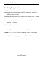
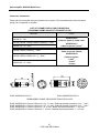
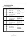
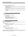
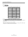
SUMMARY CHART OF BRAKING ENERGY DISSIPATION ARRANGEMENTS FOR POWER
SUPPLY MODULES
12 kW
POWER
SUPPLY
INTERNAL
RESISTOR
25 kW POWER SUPPLY
INTERNAL
RESISTOR
EXTERNAL RESISTOR
RE 91002
RE 91001
Resistor value
Ω
22 (66)
22
12
27
Max. current
A
32 (10)
32
60
26
Pulse power
kW
22(7.5)
22
40
18
Permanent power
kW
1.1 (0.37)
1.1
4.5
2
Max. non-repeat time
s
2
2
2
2
Max. repeat cycle time
s
0.2
0.2
0.2
0.2
Repetition
%
5
5
5
5
Max. non-repeat time
s
N/A
N/A
5
5
Max. repeat cycle time
s
N/A
N/A
0.5
0.5
Repetition
%
N/A
N/A
12
12
ST2 in position 2-3 (Int Res)
ST2 in position 1-2 (Ext Res)
(--) Values for reduced ventilation racks.
Max. current : Maximum controlled current, the resistor is activated at 700 V, the controlled
current is equal at most to 700 / resistor value.
Pulse power : Maximum power dissipated by the resistor, this power can only be demanded for
short periods and in keeping with a specific cycle.
Permanent power : Mean power that can be dissipated permanently by the resistor.
Max. non-repeat time : Maximum time in seconds for which pulse power can be demanded (from
cold); the resistor must be allowed to cool before braking again. With internal resistors,
temperature is monitored by a thermal sensor.
Max. repeat cycle time : Maximum time in seconds during which pulse power can be demanded
provided that the power is established for only a certain percentage of the total time (repetition).
N.B. The characteristics given for external resistors correspond to natural ventilation conditions of
these resistors and at an ambient temperature not exceeding 30°C.
13
PVD 3464 GB 04/2004
Servoamplifier DIGIVEX Multi Drive
Regeneration monitoring.
• Upon starting, detection of resistor presence. This prohibits starting (OK relay remains
open) if the resistor is broken or short-circuited (strap on terminal block B3 in wrong
position).
• In addition monitoring is carried out at each regeneration period.
• During operation the internal resistor temperature is monitored.
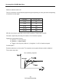
Calculation of power dissipation by braking resistor
The permanent and pulse power values shown in the previous table are limited by the braking
resistor characteristics.
Where the application includes intensive cycles or long periods of deceleration, the mean power to
be dissipated by each drive must be calculated.
2
J⎛ N ⎞
Power (Watts) = ⎜
⎟ .f
2 ⎝ 9.55 ⎠
J : Moment of inertia of servomotor and load, in kgm2.
N : Angular speed of motor shaft at start of braking, in rpm.
f : Repetition frequency of braking cycles in s-1.
The formula is for the worst-case scenario. Where the mechanical parts produce substantial
friction or reverse yield is low, the power to be dissipated may be substantially less.
The total power to be dissipated from all drives must not exceed the permissible permanent power
for the resistor. Durations and repetitions must not exceed the values in the preceding table.
14
PVD 3464 GB 04/2004
Servoamplifier DIGIVEX Multi Drive
1.5 DIGIVEX Drive SERVOAMPLIFIER
1.5.1 Presentation
DIGIVEX servoamplifiers are IGBT four-quadrant, transistor control modules for auto-drive
(brushless) synchronous motors with resolvers.
The power supply and regulation supply are provided by two 550 V buses located in the double
Europe rack which also contains the DIGIVEX Power Supplymodule.
Customized requirements for the motor - drive unit (servo-control parameters) are entered :
⇒ either using a PC with DIGIVEX - PC software under Windows
⇒ or using a display and parameter setting terminal.
These parameters are placed in two EEPROM stores :
⇒ one fixed store for DIGIVEX parameters
⇒ one plug-in store for application-specific parameters.
Modules come in three sizes and five ratings: 2/4, 4/8, 8/16, 16/32 and 32/64.
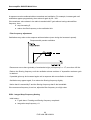
1.5.2 General Characteristics
1.5.2.1 Functions
Motor phase law control to obtain the maximum torque-speed working range.
Resolver power supply and digital demodulation providing rotor position and speed
measurement.
Digital processing of current and PWM loops and of power-related monitoring features : mean
and rms current limitations, zero torque setting, etc.
Digital processing of speed loop, comprising :
• loop optimisation (P, Pl or Pl2 correctors)
• scaling (10 V = max. N)
• introduction of anticipatory actions:
♦ gravity compensation (fixed torque)
♦ compensation for dry friction, fixed value depending on direction of rotation
♦ viscous friction proportional to speed
♦ compensation of acceleration torque
• second-order filter for reducing resonance at high frequencies
• analogue-digital conversion of speed or current reference
• memorisation of the 30 previous faults
• integration of "stimuli" for exciting the system and oscilloscope function for displaying
internal variables.
15
PVD 3464 GB 04/2004
Servoamplifier DIGIVEX Multi Drive
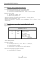
1.5.2.2 Electrical Characteristics
Module Power Supply
From the DIGIVEX Power Supply via the rack power bus.
- Maximum voltage :
- Rated voltage
:
- Minimum voltage :
750 V
540 V
200 V
Low-level auxiliary power supply
The DIGIVEX Drive internal voltages (5 V, ±15 V) are taken after chopping and galvanic insulation
from the low-level bus. Same voltage values as the power bus.
DIGIVEX Drive Module
DIGIVEX Drive MODULE
2/4
4/8
8/16
16/32
32/64
Permanent current
(sinusoidal peak)
2A
4A
8A
16 A
32 A
Pulse current
(sinusoidal peak)
4A
8A
16 A
32 A
64 A
Power dissipated
20 W
35 W
70 W
130 W
260 W
Low-level consumption*
20 W
20 W
20 W
20 W
25 W
∗ Add 5 W if an encoder emulation option card is used
16
PVD 3464 GB 04/2004
Servoamplifier DIGIVEX Multi Drive
DIGIVEX Drive GENERAL TECHNICAL CHARACTERISTICS
Power loss with altitude
Power loss of 1% per 100 m above 1000 m up to maximum
4000 m.
Operating temperature
and relative humidity
Normal use: 0 to +40°C
Power loss of 20 % per 10°C above 40°C m up to maximum
60°C
85 % (without condensation).
Storage temperature
-30°C to + 85°C
Chopping frequency
8 kHz
Current bandwidth
to 600Hz -3dB
Speed bandwidth
Up to 300 Hz
Minimum speed
0.05 rpm or 1/30,000 of maximum speed
Maximum speed
Controlled by DIGIVEX: 100,000 rpm
Static speed accuracy for zero
With digital reference : 0.1% (field bus).
load variation at rated current
With analogue reference: 1% regardless of speed
and for rated voltage of DIGIVEX
Electrical protection
Galvanic insulation of power bridge.
Mean current protection in line with drive calibre.
Pulse current protection of drive and motor.
Rms current protection of motor.
Protection against short circuits at bridge output.
Fuse protection against internal short circuits.
Mechanical protection
IP20 to IEC 529 when rack-mounted
Other protective features
Motor temperature
Drive temperature
Cooling air temperature
Brake supply
Resolver supply
17
PVD 3464 GB 04/2004
Servoamplifier DIGIVEX Multi Drive
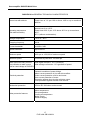
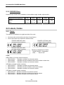
1.6 Compliance with Standards
Servomotor
HX, HS and HD range servomotors meet Directive 73/23/EEC of 19th February 1973 (as
amended by Directive 93/68/EEC of 22nd July 1993) and comply with standards EN 60034-1 and
IEC 34-1/1994. The entire range bears the CE marking.
Compliance with these standards requires installation in accordance with our recommendations
(see servomotor commissioning and use instructions). In addition, the installation must be on a
mechanical support providing good thermal conduction and not exceeding 40°C in the vicinity of
the servomotor flange.
Main standards that the servomotors comply with:
IP protection
Flange
Shaft end
Flange tolerance
Noise
Balancing
Electrical values
AFNOR
NF60034-5
C 51-104
C 51-105
C 51-119
C 51-111 (add. 1)
C 51-111
DIN/VDE
DIN 40050
DIN 42948
DIN 42946
DIN 42955
DIN 45665
VDE 0530/1
IEC 34-5
IEC 34-5
IEC 72
IEC 72
IEC 72
IEC 34-9
ISO 2373
IEC 34-1
DIGIVEX
The CE mark is affixed to the front panel of the rack (on the ventilation block).
DIGIVEX DRIVE and DIGIVEX POWER SUPPLY bear the CE mark under European Directive
89/336/EEC as amended by Directive 93/68/EEC on electromagnetic compatibility. This European
Directive refers to the harmonised generic standards EN50081-2 of December 1993 (Electrical
Compatibility - Generic Standard for Emissions - Industrial Environments) and EN50082-2 of June
1995 (Electromagnetic Compatibility - Generic Standard for Immunity - Industrial Environments).
These two harmonised generic standards are based on the following standards :
• EN 55011 of July 1991 : Radiated and conducted emissions
• EN 50140 of August 1993 and ENV 50204 : Immunity to radiated electromagnetic
fields
• EN 61000-4-8 of February 1994: Mains frequency magnetic fields
• EN 61000-4-2 of June 1995 : Electrostatic discharge
• ENV 50141 of August 1993 : Interference induced in cables
• EN 61000-4-4 of June 1995 : Rapid transient currents
Compliance with the reference standards above implies adherence to the instructions and wiring
diagrams in the technical documents supplied with the appliances.
Incorporation in Machinery
The design of the equipment means it can be used in machinery covered by Directive 89/392/EEC
(Machine Directive) provided that it is integrated (or incorporated and/or assembled) in
accordance with the rules-of-the-art by the machinery manufacturer and in keeping with the
instructions in this booklet.
18
PVD 3464 GB 04/2004
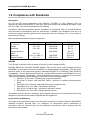
Servoamplifier DIGIVEX Multi Drive
2. SPACE REQUIREMENTS, ASSEMBLY,
LABELLING, CODES
2.1 Dimensions and mounting
Two sizes of rack are available in three versions :
•
•
Rack to accommodate six single format servoamplifier modules in addition to the POWER SUPPLY
Half-rack to accommodate three single format servoamplifier modules in addition to the POWER
SUPPLY.
For each size, the following three versions are available :
•
•
•
Standard ventilation and internal braking energy dissipation resistor;
Standard ventilation and external braking energy dissipation resistor;
Compact ventilation and internal braking energy dissipation resistor (reserved for cases where all
DIGIVEX DRIVES are less than or equal to 4/8 calibre).
The fans are powered by the low-level source from the POWER SUPPLY.
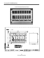
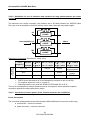
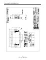
2.1.1 Rack and Power Supply
13 LOCATION SINGLE MODULE RACK
19
PVD 3464 GB 04/2004
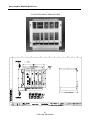
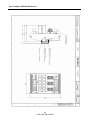
Servoamplifier DIGIVEX Multi Drive
6 LOCATION SINGLE MODULE RACK
20
PVD 3464 GB 04/2004
Servoamplifier DIGIVEX Multi Drive
3 LOCATION SINGLE MODULE RACK
21
PVD 3464 GB 04/2004
Servoamplifier DIGIVEX Multi Drive
2.1.2 DIGIVEX Drive
Double Europe format cards, available in three widths: single, double, triple module.
2/4
1.3 kg
4/8
1.3 kg
55.9 mm
55.9 mm
DIGIVEX Drive MODULE
Weight
Width
8/16
1 3 kg
16/32
3.1 kg
32/64
5 kg
55.9 mm 111.8 mm 167.6 mm
2.2 Labels, Codes
2.2.1 Racks
Two stickers are affixed to the right-hand side of the rack :
•
•
One shows the serial number and date of manufacture.
One is equivalent to the specimen stickers below :
DIGIVEX 84E Rack Label
(6 single-module locations)
DIGIVEX 51E Rack Label
(3 single-module locations)
DIGIVEX 84E Rack Label
(13 single-module locations)
Meaning of indications on labels :
. RACK DIGIVEX : Designation
. DRA ....…: Rack Code
Codes
84Ex2 Racks (13 single module locations)
• DRA3128V63
Standard ventilation and internal resistor
• DRA3128L63
Standard reduced ventilation and internal resistor resistor bus
• DRA3128R43
Standard ventilation and external resistor
84E Racks (6 single module locations)
• DRA3168V63
Standard ventilation and internal resistor
• DRA3168V23
Standard reduced ventilation and internal resistor
• DRA3168R43
Standard ventilation and external resistor
51E Racks (3 single module locations)
• DRA3165V43.....Standard ventilation and internal resistor
• DRA3165V23.....Standard reduced ventilation and internal resistor
• DRA3165R23.....Standard ventilation and external resistor
22
PVD 3464 GB 04/2004
Servoamplifier DIGIVEX Multi Drive
2.2.2 Power Supply
Two labels are fastened to the rear connectors of the DIGIVEX Power Supply module:
⇒ One shows the serial number and date of manufacture;
⇒ One is equivalent to the specimen stickers shown below
DIGIVEX Power Supply 12kW
Meaning of label indications :
- Convertisseur CA/CC
- DPS ---- E: 3 x 400 V --A
- fn: 50/60 Hz
- S: 550 V -- A
- Charge: DXD
- Class: 1
DIGIVEX Power Supply 25 kW
AC / DC converter
DIGIVEX Power Supply code
Input voltage and current
Authorised frequency range
Output voltage and current
Type of load (DIGIVEX DRIVE module)
Service class to standard EN 60146, 1 = permanent
Codes
DIGIVEX Power Supply
DPS0612: 12 kW DIGIVEX Power Supply
DPS0625: 25 kW DIGIVEX Power Supply
EXTERNAL ENERGY DISSIPATION RESISTORS
RE 91001 : 2000 W - 27 Ω resistor
RE 91002 : 4500 W - 12 Ω resistor
RE 90020 : Pair of wall fastening resistor support
23
PVD 3464 GB 04/2004
Servoamplifier DIGIVEX Multi Drive
2.2.3 DIGIVEX Drive
Markings affixed to appliance:
•
Two labels are affixed to the rear connectors :
∗ one showing the serial number and date of manufacture
∗ one in accordance with the model below.
Digpl28.T
Meaning of label markings :
- Convertisseur CC/CA
- DXD---- E: 550 V -- A
- Class
- S: 0-540V -- Â
: DC/AC converter
: DIGIVEX Drive module code
: Input voltage and current
: Service class to standard NF EN 60146, 1 = permanent
: Output voltage and permanent output current (peak Amp)
•
One label on the front panel, on the handle, indicating :
∗ DXD module serial number
∗ DXD module code
∗ one line for miscellaneous information
•
One label on the EEPROM (subprint SZ 6608B)
∗ DXD module code
∗ corresponding motor
∗ maximum speed (N max.) for a given reference (usually 10 V)
•
One label on the EEPROM
AP501V3).
(marked U47) indicating the software reference (e.g.
The drive customized parameters are stored in this plug-in EEPROM memory. The parameters
can be read by :
⇒ DIGIVEX - PC software
⇒ Display / parameter setting terminal (see following sections)
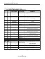
Codes
DXD06002
DXD06004
DXD06008
DXD06016
DXD06032
:
:
:
:
:
DIGIVEX Drive axis module 2/4
DIGIVEX Drive axis module 4/8
DIGIVEX Drive axis module 8/16
DIGIVEX Drive axis module 16/32
DIGIVEX Drive axis module 32/64
24
PVD 3464 GB 04/2004
Servoamplifier DIGIVEX Multi Drive
3. ELECTRICAL CONNECTIONS
3.1 General Wiring Requirements
3.1.1 Electromagnetic Compatibility
GROUNDING
•
•
Adhere to all local safety regulations concerning grounding.
Use a metal surface as a ground reference plane (e.g. cabinet wall or assembly grid).
This conducting surface is termed the potential reference plane (PRP). All the
equipment of an electrical drive system is connected to the PRP by a low impedance
(or short distance) link. First make sure that the connections conduct electricity
properly by scraping off the surface paint if necessary and by using fan washers. The
drive will be grounded by a low impedance link between the PRP and the ground rod
on the front panel of the DIGIVEX rack. If this link is longer than 30 cm, use a flat braid
or standard wire instead.
CONNECTIONS
•
Avoid routing low level cables (resolver, input/output, NC or PC links) alongside power
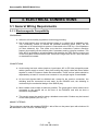
cables (power supply or motor). Also avoid routing the supply cable and motor cables
together in order to conserve mains filter attenuation. These various cables should be
separated by at least 10 cm and never crossed or only at right angles if unavoidable.
•
All low level signals shall be shielded and, except for the resolver connection, the
shielding shall be connected at both ends. At the DIGIVEX end, the shielding is
continued by the mechanical design of the SUB-D plug.
•
Motor cables must be kept as short as possible. The green/yellow motor lead must be
connected to the ground rod on the front of the DIGIVEX rack with as short a
connection as possible.
•
This usually saves the need for using a shielded motor cable. Chokes may be inserted
on the motor phases (see 3.4.3.2).
MAINS FILTERING
The equipment complies with standard EN55011 with a filter on the power input with minimum 60
dB attenuation in the 150 kHz - 30 MHz range.
25
PVD 3464 GB 04/2004
Servoamplifier DIGIVEX Multi Drive
Avoid running cables together ahead of and after the filter.
For appliances requiring voltage adaptations, it is preferable to use a transformer. The transformer
neutral is to be connected to earth by as short a wire as possible to the potential reference plate.
For single-phase transformers, one of the two alternate outputs will be connected to the potential
reference plate.
Filters sometimes have high leakage currents. In this case, the standard wiring diagrams must be
respected when fitting.
OTHER REQUIREMENTS
The self-inducting components must be protected against interference : brakes, contactor or relay
coils, fans, electro-magnets, etc.
The front panels of the rack-mounted appliances must be screwed down.
HANDLING MODULES AND CONNECTORS
Do not remove or fit the modules while the power is on.
While the power is on do not connect or disconnect :
• the power connectors.
• the resolver and encoder emulation connections.
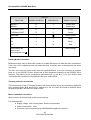
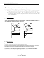
3.1.2 DIGIVEX DRIVE SUB-D Plug, general
For immunity from interference it is essential for the rack to be correctly connected to the ground
of the electrical cabinet and to use EMI/RFI shielded type SUB-D plug caps (metal with shielding
braid connected). Make sure the SUB-D connectors and their caps are properly fixed (lock screws
must be tight).
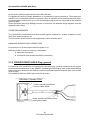
The shielding inside the SUB-D caps must be as shown :
GROUND CONNECTION
Fold the shielding braid back
over the cable sheath
Solder between the braid and the
green/yellow cable.
26
PVD 3464 GB 04/2004
Servoamplifier DIGIVEX Multi Drive
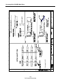
3.2 Typical Connection Diagram
See drawings FELX 304541GB and FELX 304557GB below.
27
PVD 3464 GB 04/2004
Servoamplifier DIGIVEX Multi Drive
28
PVD 3464 GB 04/2004
Servoamplifier DIGIVEX Multi Drive
29
PVD 3464 GB 04/2004
Servoamplifier DIGIVEX Multi Drive
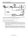
3.2.1 Surge Suppressor
- KM:
- AP:
Power Contactor
Surge Suppressor
The power contactor coil KM should necessary have a surge suppressor AP connected in order
not to destroy prematurely the internal relay contact of the drive. This module should be use
whether the power contactor supply is AC or DC.
The relay manufacturers (Telemecanique: LC1 series, ABB: B series,…) provide surge
suppressors fitted relays wether the power contactor supply is AC or DC for various voltages (RC
module, Diode+Zener Diode, Varistor,…).
30
PVD 3464 GB 04/2004
Servoamplifier DIGIVEX Multi Drive
3.3 Power Supply connection
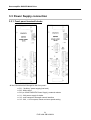
3.3.1 Front panel terminal blocks
B3
All the connections are brought to the front panel :
• B1 : "Auxiliary" power supply (low level)
• B2 : Mains input
• B3 (on 25 kW DIGIVEX Power Supply): external resistor
• X1 : 24V power supply for brake
• X2 : main contactor automatic control interface
• X3 : 24V, +/-15V outputs, Reset and zero speed setting
31
PVD 3464 GB 04/2004
Servoamplifier DIGIVEX Multi Drive
3.3.2 Terminal block characteristics
Recap showing for terminal blocks B1, B2, B3, X1, X2 and X3 (DIGIVEX Power Supply) :
• terminal type.
• maximum permissible cable cross-section (S) for the terminal block.
• recommended torque value (T) for the terminal block.
TERMINAL
B1
B2
12 kW POWER SUPPLY
25 kW POWER SUPPLY
screw-type, S = 4 mm² flexible wire
screw-type, S = 4 mm² flexible wire
S = 6 mm² rigid wire, T = 0.8 Nm
S = 6 mm² rigid wire, T = 0.8 Nm
screw-type, S = 6 mm² flexible wire
screw-type, S = 6 mm² flexible wire
S = 10 mm² rigid wire, T = 1.8 Nm
S = 10 mm² rigid wire, T = 1.8 Nm
B3
-
screw-type, S = 4 mm² flexible wire
S = 6 mm² rigid wire, T = 0.8 Nm
X1 à X3
spring-type, S = 2.5 mm≤
spring-type, S = 2.5 mm≤
3.3.3 Power component dimensions
Applicable to components ahead of the DIGIVEX POWER SUPPLY (fuses, cables, contactor,
etc.), dimensions depend on :
• permanent currents (sinusoidal peak) at low speed of each motor as shown in
characteristics (Î0).
• the drive simultaneity coefficient.
Supposing this coefficient is equal to 1 and cosϕ= 1, gives :
P mains ≅ 1.1 U rms ΣÎ0
P
Irms mains =
Urms.√3
32
PVD 3464 GB 04/2004
Servoamplifier DIGIVEX Multi Drive
MAINS INPUT
POWER 400 V
kW
∑ Î0
Â
LINE CURRENT for
mains Urms = 400 V
A eff.
FUSE
RATING
Type gG
MAINS
FILTER
FR03016
4.4
10
6.5
10
6.6
15
9.5
16
13.2
30
19
32
24.2
55
36
50/63
FR03036
The cable cross-section and contactor rating must be selected accordingly.
3.3.4 Connection to mains
400 V rms three-phase mains supply via terminal block B2 : terminals U1 - V1 - W1
Single-phase operations possible (downgraded mode, please ask for details).
50/60 Hz mains supply voltage must be greater than 200 V rms and less than 470 V rms; a
transformer or an auto transformer is necessary for use with 460 V ± 10% or 480 V ± 10% mains
supply.
Current :
20 A rms for 12 kW POWER SUPPLY
40 A rms for 25 kW POWER SUPPLY
Power loss with temperature :
• Power loss of 2% per °C above 40°C.
• Max. ambient temperature 60°C.
A thermal sensor trips the OK relay when the dissipater reaches 85°C.
Power loss with altitude: Power loss of 1% per 100 m above 1,000 m.
"MAIN SUPPLY " terminal block B2: Marked U1 - V1 - W1.
Mains monitoring :
• No phase (see strap ST1).
• Maximum mains voltage (470 V).
Power bus monitoring :
• Maximum bus voltage (750 V).
• Minimum bus voltage (200 V).
Power dissipated :
• 12 kW power supply : 50 W.
• 25 kW power supply : 100 W.
33
PVD 3464 GB 04/2004
Servoamplifier DIGIVEX Multi Drive
3.3.5 Low-Level and Auxiliary Supply
Terminal block B1.
Each DIGIVEX Drive derives its low-level supply from a low-level supply bus and restores the ±
15 V / 5 V it requires through a chopper supply and transformer.
The « low-level supply » bus, whose voltage is between 200 V and 750 V, may be obtained in
either of two ways :
⇒ either via terminal block B1, from a single-phase source, which may be :
• 400 V single-phase, from 48 to 62 Hz between two phases ahead of the main switch;
• a separate 400 V source. In this case a 200 VA isolating transformer must be
provided (e.g. primary 230 V ± 10%, secondary 400 V ± 10%)
The advantage with these solutions is that the power part can be cut out separately while the LED
fault display and the encoder emulation counting capability are maintained.
⇒ Or from the power bus. In this case only terminal block B2 need be connected.
Drawback : If power fails, regulation supply and above all any encoder emulation card information
is lost.
Internal fuse :
• Marked F1, protects the chopped supply : type 500V / 1.6A
Auxiliary supply monitoring, supply present.
• Auxiliary supply also provides 24 V dc for the rack fans, and the rack is therefore fancooled as long as the low-level supply is maintained.
Low-level consumption: 30 W.
34
PVD 3464 GB 04/2004
Servoamplifier DIGIVEX Multi Drive
3.3.6 External Energy Dissipation Resistor
For 25 kW DIGIVEX POWER SUPPLY with external resistor option :
• No link between terminals 2 and 3 of terminal block B3.
• The resistor is connected between terminal 1 and 2 of terminal block B3.
Maximum current in cable :
• With RE 91001 (2 000 W) : 30 A
• With RE 91002 (4 500 W) : 60 A
Cable type: unshielded, cross-section 2.5 mm² for 2 000 W, 4 mm² for 4 500 W.
Maximum recommended distance : 10 m.
Resistor end: connection by terminal box through packing gland PG 16 for 10 mm - 14 mm
diameter cable.
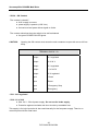
3.3.7 Control signal connection (terminal Blocks X2 and X3)
Plug-in terminals
TERMINAL BLOCK X2
1-2
Output
« READY » contact
3-4
Output
« OK » contact
Potential free contacts
Max. U = 250 V I =1A
Cut-out power = 250 VA
(ohmic load)
- X2/1.2 : Ready Contact
The contact is closed if :
• the auxiliary bus (low-level) is correct, >290 V dc on powering up,
• at least one drive is in the rack,
• drives signalled no faults when low-level supplies appeared.
This contact authorises the main switch to be closed
• the red POWER OFF LED glows.
35
PVD 3464 GB 04/2004
Servoamplifier DIGIVEX Multi Drive
- X2/3.4 : OK Contact
The contact is closed if :
• AUX. supply is correct,
• power supply is present (>200 V dc)
• the low-level and power drives signal no faults.
The contact authorises the main switch to be self-maintained
• the green POWER ON LED glows.
CAUTION :
Opening the OK contact must cause the main contactor to open with a max 100 ms
delay.
TERMINAL BLOCK X3
1
Output
24 V regulated
2
Output
0V of 24 V
3
Output
15 V regulated
4
Output
0 V of ±15 V
5
Output
-15 V regulated
6
Input
+ Reset
7
Input
- Reset
8
Input
+ Emergency Stop
9
Input
- Emergency
- X3/1 24 V regulated
- X3/2 0 V of 24 V
• Max. 24 V - 50 mA power supply. Do not use for brake supply.
• Protection against overloads and short circuits by resettable fuse.
This supply is for logic inputs but is also used internally for the fan power supply. There is no
common point with the metal case.
36
PVD 3464 GB 04/2004
Servoamplifier DIGIVEX Multi Drive
- X3/3 +15 V regulated
-X3/4 0 V of 15 V
- X3/5 -15 V regulated
• max. ±15 V - 10 mA power supply.
• Protected by 47 Ω resistor.
This supply is common with the internal supply of the POWER SUPPLY module. There is no
common point with the metal casing.
- X3/6 to X3/9 Logic inputs
Common characteristics:
• 24 V dc optocoupled inputs (insulation voltage 1 kV)
• type two inputs to IEC 1131-2.
These inputs may be connected directly to PNP type outputs (external load resistor not required).
MIN.
TYPICAL
MAX.
Level 0 input voltage
-
0V
5V
Level 1 input voltage
11V
24V
30V
Level 0 input current
-
0mA
2mA
Level 1 input current
7mA
13mA
15mA
Response time Ton (0 to 1)
-
1ms
-
Response time Toff (1 to 0)
-
1ms
-
- X3/6 and X3/7
Reset
A 24 V rising edge applied across X3/6 compared with X3/7 resets the system after a power
supply or drive fault (clear).
Note that the front panel reset button can also be used, or turning off the power completely (power
and auxiliaries).
This control has no effect during normal operation.
- X3/8 and X3/9
Emergency Stop , in speed loop mode only
A 24 V source must be applied between terminals X3/8 (+) and X3/9 (-) to enable drive operation:
the 24 V may be taken from X3 terminals 1 and 2.
The collapse of 24 V across terminals X3/8 and X3/9 acts on all the drives causing dynamic
braking. This is an aid for category 1 or 2 stops to standard EN 60204.
37
PVD 3464 GB 04/2004
Servoamplifier DIGIVEX Multi Drive
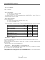
3.3.8 Terminal Block X1 "Brake Supply"
Plug-in terminal block.
This terminal block can accommodate a 24 V power supply for brakes fitted to motors. It is
redistributed by the drives to the motor power terminal blocks.
Regulated / filtered 24 V ± 10% voltage - Overload protection by 26 Joule varistance. This
protection is operational from 30 V.
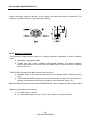
3.4 DIGIVEX Drive connection
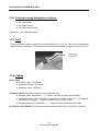
3.4.1 Front plate terminals
All the inputs/outputs required for operation are grouped on the
front panel as :
- one or two terminal blocks grouping the servomotor,
brake and thermal protection connections
- one X1 resolver connector, 9-pin female contact SUB-D
for resolver
- one X2 input/output connector, 25-pin female contact
SUB-D for all logic and analog inputs/outputs
- one RS232 X3 connector, 9-pin female contact SUB-D
for the RS232 link with the PC.
The motor ground is to be connected to the "ground bar" located
under the rack. The SUB-D plugs used must be metallised (or
metallic) and provide continuous shielding to the rack metal
ground.
As option 1 encoder connector, 9-pin male contact SUB-D for
pulse encoder emulation.
38
PVD 3464 GB 04/2004
Servoamplifier DIGIVEX Multi Drive
Terminal Blocks B1/B2: Power, Thermal Protection and Brake
• Terminal block B1 for calibre 2/4, 4/8, 8/16 and 16/32
• Terminal block B1 and B2 for calibre 32/64
DIGIVEX Drive calibres 2/4, 4/8, 8/16 and 16/32
•
One plug-in terminal block B1 comprising :
•
•
•
terminals 1, 2 and 3 marked U2, V2 and W2 for power.
terminals 4 and 5 for motor thermal protection (TH) input (current less than 3
mA).
terminals 6 and 7, 24 V for brake supply (BR).
DIGIVEX Drive calibre 32/64
- One fixed terminal block B1 (screw
terminals), terminals 1, 2 and 3
(U2, V2, W2) for power.
- One plug-in terminal block B2 comprising :
♦ terminals 1 and 2 for motor thermal
protection (TH) input (current less than 3
mA).
♦ terminals 3 and 4 (marked Br+ and -) 24
V for braking supply (BR).
39
PVD 3464 GB 04/2004
Servoamplifier DIGIVEX Multi Drive
24 V brake output terminals : Outputs assigned to motor brake control (terminal 6 to positive,
terminal 7 to negative for calibres 2/4 to 16/32; terminal 3 to positive, terminal 4 to negative for
calibre 32/64).
Normal braking voltage: 24 V dc ±10%.
The 24 V source enters the rack via the DIGIVEX POWER SUPPLY terminal X1. It is supplied
externally and passes through the DIGIVEX unit to be redistributed to the drives. Protection is
provided by a resettable 1.8 A fuse for calibres up to and including 8//16, and a 2.7 A fuse for
calibres 16/32 and 32/64.
Voltage is monitored by the DIGIVEX DRIVE software and, if a brake is engaged, the drive
acknowledges the disappearance of the 24 V.
3.4.2 Terminal blocks and sockets characteristics
Summary chart showing for terminal blocks (or sockets) B1, B2, X1 - X4 (DIGIVEX Drive) :
• terminal block type (or socket).
• maximum cross-section (S) of cable for the terminal block (or socket).
• recommended torque value (T) for the terminal block.
TERMINAL
DIGIVEX Drive 4/8 - 16/32
B1
spring-type, S = 2.5 mm≤
B2
X1
X2
X3
X4
Resolver SUB-D S = 0.5 mm≤
Input/output SUB-D S = 0.5 mm≤
RS 232 SUB-D S = 0.5 mm≤
Encoder S = 0.5 mm≤
DIGIVEX Drive 32/64
screw-type, S = 6 mm≤ flexible wire,
S = 10 mm≤ rigid wire, T = 1.8 Nm
spring-type, S = 2.5 mm≤
Resolver SUB-D S = 0.5 mm≤
Input/output SUB-D S = 0.5 mm≤
RS 232 SUB-D S = 0.5 mm≤
Encoder S = 0.5 mm²
3.4.3 DIGIVEX Drive Servomotor connection
3.4.3.1 "POWER" Cable Definition
The power/drive connector cables must have as a minimum requirement :
• 3 insulated conductors connected to U, V, W phases. Cross-sections as in the table
below. The internal chokes of the DIGIVEX Drive mean that, as a general rule, there is
no need to use shielding on the three power conductors.
• 1 ground conductor (green/yellow).
• 2 shielded twisted pairs for connection of the motor thermal protection. Cross-section of
about 1 mm².
• 2 shielded twisted pairs for connection of the holding brake (if fitted). Cross-section of
about 1 mm².
• 1 “shielding continuity” conductor (green/orange) to be connected to the servoamplifier
earth
40
PVD 3464 GB 04/2004
Servoamplifier DIGIVEX Multi Drive
Power cable cross-section
Cable cross-sections shown in the table below make allowance for :
• rated drive current;
• motor/drive distance, loss in useful voltage = RI.
• ambient temperature, cable loss of Joules = RI2.
• standardised increase of cable cross-sections.
PARVEX proposes cables for distance of up to 50 m and ambient temperatures of less than 40° C.
Distance → 0m
50m
DIGIVEX
Calibre
2/4 and 4/8
100m
200m
PARVEX SUPPLY
L = 50m, θ ≤ 40°C
Cable cross-section in mm≤
0.5
1
2.5
1
8/16
1.5
2.5
6*
2.5
16/32
2.5
6*
10*
2.5
32/64
6
10*
16*
6
* Cross-sections incompatible with DIGIVEX DRIVE power terminal blocks (See § 3.4.2).
Fit an intermediate terminal block close to the DIGIVEX DRIVE.
41
PVD 3464 GB 04/2004
Servoamplifier DIGIVEX Multi Drive
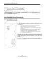
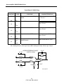
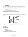
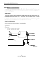
3.4.3.2 Guidelines for use of inductors and resistors for long cables between the motor
and drive
The inductors and, where necessary, the resistors are to be fitted between the DIGIVEX Multi
Drive (as close as possible to the drive) and the motor when used with long cable lengths.
U2
CHOKE
Motor
Servoamplifier V2
CHOKE
W2
CHOKE
References of inductors (Dimensions : see § 3.5.5)
L ≤ 20 m
20 < L < 30 m
30 ≤ L < 70 m
70 ≤ L < 100 m
L ≤ 15 m
15 < L < 20 m
20 ≤ L < 50 m
50 ≤ L < 70 m
2/4 – 4/8
-
DSF02
DSF02
8/16
-
-
DSF02
32/64
-
-
SF02025
DIGIVEX
Multi Drive
Normal
Cable
length (L) Shielded
•
•
•
Not
recommended
SF02032 +
resistor
SF02025
DSF02: three inductances of 50 mH damped by resistors to rise on rail DIN
For lengthes superior to 100 m, consult us.
Damping resistor to be used with SF02032 :RE 40008 470 Ω 25 W
The use of self dampers for shorter distances can be envisaged to reduce parasite reception,
caused by capacitive coupling with power cables.
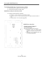
3.4.3.3 Connection to motor (power, brake, thermal protector and ventilation)
Power Connection
Two connection arrangements are provided (except HX300 which has the connector version only) :
• terminal box + resolver connector.
• power connector + resolver connector.
42
PVD 3464 GB 04/2004
Servoamplifier DIGIVEX Multi Drive
43
PVD 3464 GB 04/2004
Servoamplifier DIGIVEX Multi Drive
44
PVD 3464 GB 04/2004
Servoamplifier DIGIVEX Multi Drive
Connection cable between DMD and DSF02
45
PVD 3464 GB 04/2004
Servoamplifier DIGIVEX Multi Drive
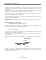
Terminal Box Connection
The clamp nuts and washers for the terminal box come in a sachet. Take care when fitting the
terminals not to loosen the connecting wires between the motor and the terminal box.
Insert the power connection lugs between the
striated washer and the flat washer.
Dipl3gb.ds4
Direction of Motor Rotation: When wired as specified a positive speed reference applied to the
drive causes clockwise rotation (as viewed from power shaft).
1 Optional brake + 24 V
2 Optional brake
3 PTC sensor
4 PTC sensor
Dipl2gb.D/W
46
PVD 3464 GB 04/2004
0V
câble ≥ 1mm²
câble ≥ 1mm²
Servoamplifier DIGIVEX Multi Drive
Connector Connection
Power can be connected using a connector as an option. The removable part of the connector
(plug) can be supplied on request.
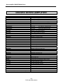
LIST OF CONNECTOR PLUGS FOR MOTORS
(STANDARD CRIMP-CONTACT STRAIGHT PLUG)
MOTOR
PLUG
HX400/ HX600, HS600/ HD600, HS800 (Î0 < 14A)
220065R1610
Cable for power 0,5 and 1mm2
220065R1611
Cable for power 2,5 mm2
HX300 (Î0 < 7A)
HS800 (14 ≤ Î0 < 32A)
220065R3611
Cable for power 2,5mm2
220065R3610
Cable for power:
6 mm2
10 mm2
16 mm2
HX800/ HD800, HS900 (Î0 < 32A)
HX800/ HD800, HD900 (32 ≤ Î0 < 60A)
HD900 (60 ≤ Î0 < 80A)
PLUG 220065R1610/1611
PLUG 220065R3610/3611
PERMISSIBLE CABLE CROSS-SECTION FOR PLUGS
PLUG 220065R1610: Power & Ground: 0.14 - 1.5 mm². Brake & thermal protection: 0.14 - 1 mm².
PLUG 220065R1611: Power & Ground: 0.75 - 2.5 mm². Brake & thermal protection: 0.14 - 1 mm².
PLUG 220065R3611: Power & Ground: 1.5 - 4 mm². Brake & thermal protection: 1 - 2.5 mm².
PLUG 220065R3610: Power & Ground: 6 - 16 mm². Brake & thermal protection: 1 - 2.5 mm².
47
PVD 3464 GB 04/2004
Servoamplifier DIGIVEX Multi Drive
PIN OUT
FUNCTION
220065R1610/R1611
220065R3610
CABLE COLOUR
BRAKE +
A
+
Green/ Red
BRAKE -
B
-
Green/ Blue
THERMAL PROT.
C
1
Orange
THERMAL PROT.
D
2
Yellow
GROUND
2
U2
1
U
Black
V2
4
V
White
W2
3
W
Red
-
-
Green/Orange
Shielding to be
connected to the
earth at the
servoamplifier end
Green/Yellow
Holding Brake Connection
Brushless motors may be fitted with a brake of suitable dimensions to hold the drive immobilised.
If 24 V dc ±10% is applied across the brake terminals, the brake disc is released and the motor
can rotate.
The 24 V dc current for brake control must be regulated/filtered. It is to be connected to terminal
block X1 of the DIGIVEX Power Supply and is then distributed internally to the DIGIVEX Drive
modules. The brake is to be connected to terminals B1/6 (+) and B1/7 (-) for 2/4, 4/8,8/16 and
16/32 and to B2/1 and B2/2 of the DIGIVEX Drive for calibre 32/64.
Thermal protection Connection
The two terminals of the PTC probe located in the motor terminal box to be connectec to DIGIVEX
Drive terminal blocks B1/4 and B1/5 for calibres 2/4, 4/8, 8/16 and 16/32 and to DIGIVEX Drive
terminal blocks B2/1 and B2/2 for calibre 32/64.
Motor Ventilation Connection
Some motors can be delivered as fan-cooled versions.
Fan characteristics :
• Supply voltage : 400 V three-phase, 50/60 Hz as standard.
• Power consumption : 45 W
• Connector type connection (plug 220056P0200 supplied on request).
48
PVD 3464 GB 04/2004
Servoamplifier DIGIVEX Multi Drive
When connecting check the direction of fan rotation and check that airflow is produced. The
direction of airflow is shown on the dimension drawings.
View F
Dipl7gb.T/dm8.h
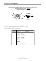
3.4.3.4 Resolver Connection
The resolver is a high precision sensor (± 10 angular minutes as standard). It must be carefully
wired :
• Separately routed power cable.
• Twisted pair (sine, cosine, excitation) with general shielding. The general shielding
must be connected to the metal cap of the SUB-D plug. Do not connect the shielding
at the motor end.
PARVEX SA can supply the cable in either of two versions :
• Separate cable, in this case wire as shown in the diagram below. Reference see §
3.5.4.
• Cable fitted with SUB-D plug at drive end and connector at motor end. This solution is
strongly recommended as the cable is ready for use. Reference, see § 3.5.4.
Maximum distance between resolver and DIGIVEX DRIVE : 200 m. Please ask about longer cables.
Maximum permissible cross-sections :
•
•
For SUB-D plug : 0.5 mm≤.
For removable connector plug. 0.14 to 1 mm² (solder or crimp-fit contacts)
49
PVD 3464 GB 04/2004
Servoamplifier DIGIVEX Multi Drive
RESOLVER REMOVABLE CONNECTOR PLUG (connection at motor end)
220065R4621 (solder contacts - standard)
220065R1621 (crimp-fit contact)
View F
"Resolver" SUB-D Plug (connection at DIGIVEX Drive end)
Maximum conductor cross-section: 0.5 mm²
CONTACT
TYPE
PURPOSE
1
Input
Cosine S1
2
Input
Sine S2
3
Input
Cosine S3
4
Input
Sine S4
5
Output
6
Output
7
Output
8
Output
9
Output
Excitation R1
0 V R2/3 Excitation
50
PVD 3464 GB 04/2004
Servoamplifier DIGIVEX Multi Drive
51
PVD 3464 GB 04/2004
Servoamplifier DIGIVEX Multi Drive
3.4.4 "Input/Output" SUB-D Plug
3.4.4.1 Inputs/Outputs description
Maximum conductor cross-section: 0.5 mm≤
CONTACT
TYPE
PURPOSE
1
AI1 +
±10 V speed or current
reference, + point
14
AI 1 -
2
AI 2 +
± 10 V speed or current
reference, - point
± 10 V analog input, + point
CHARACTERISTICS
Analog conversion :
15 bits + sign
Differential input
Analog conversion :
9 bits + sign
± 10 V analog input, - point
Input assigned to external
current limitation.
10 V = max. current
15
AI 2 -
3
A01
Analog output ±10V, + point
ANA1
16
0V
0V of analog output
Output assigned to speed
measurement
10V = maximum speed
4
A02
Analog output ±10V, + point
ANA2
17
0V
0V of analog output
Output assigned to current
measurement
10V = maximum current
9
EL1 +
SPEED RANGE
21
10
EL1 LI2 +
22
11
LI2 LI3 +
Speed range choice
CW: enables clockwise rotation if (see characteristics on
input is active (level 1)
following pages)
These inputs must be
supplied with 24 V
CCW: enables counter-clockwise
rotation is input is active (level 1)
Analog conversion
7 bits + sign
Max. voltage = 10 V
Max. current = 3 mA
Protected against short
circuits
Analog conversion
7 bits + sign
Max. voltage = 10 V
Max. current = 3 mA
Protected against short
circuits
24 V optocoupled logic inputs
type 2 under IEC standard
1131-2 5
LI3 23
AI = Analog Input, LI = Logic Input, AO = Analog Output, LO = Logic Output
52
PVD 3464 GB 04/2004
Servoamplifier DIGIVEX Multi Drive
"Input/Output" SUB-D Plug
CONTACT
TYPE
12
LI4 +
24
6
LI4 LO1
18
0V
Logic
7
LO2
19
0V
Logic
8
20
13
25
PURPOSE
Torque : torque enable if input is
HIGH
CHARACTERISTICS
Type 2 logic input under IEC
1131-2.5
Drive OK
24 V optocoupled PNP output
max. 50 mA.
Speed detection OUT1
24 V optocoupled PNP output
max. 50 mA
LO3
Speed detection OUT2
24 V optocoupled PNP output
max. 50 mA
0V
Logic
+24V
logic
0V
Logic
Supply available for logic
inputs/outputs
max. 50 mA via R = 22 Ω
AI = Analogue Input, LI = Logic Input, AO = Analogue Output, LO = Logic Output
4.7 nF
SPEED REFERENCE INPUT
15 BITS + SIGN
2.2 nF
22 K
22 K
22 K
22 K
22 K
22 K
2.2 nF
4.7 nF
Dipl17gb.D/W
53
PVD 3464 GB 04/2004
Servoamplifier DIGIVEX Multi Drive
CURRENT LIMITATION INPUT
9 BITS + SIGN
22 K
4.7 nF
11 K
22 K
4.7 nF
22 K
22 K
4.7 nF
4.7 nF
DIGPL17.D/18W
11 K
Dipl17gb.D/pl18.W
ANALOGUE OUTPUTS
SORTIES ANALOGIQUES
3.3 nF
40K
47.5 Ohms 47.5 Ohms
2.2 nF
Dipl17gb.D/pl31.W
Logic Input Characteristics
• optocoupled 24 V dc inputs (insulation voltage 100 V)
• type 2 inputs to standard IEC 1131-2
• these inputs may be connected directly to PNP type outputs (external load resistor not
necessary)
LOGIC INPUTS
ENTREES LOGIQUES
4.7V
78L05
5K
1.5 K
10 K
Dipl17gb.D/pl19.W
54
PVD 3464 GB 04/2004
Servoamplifier DIGIVEX Multi Drive
MIN.
TYPICAL
MAX.
Level 0 input voltage
Level 1 input voltage
11V
0V
24V
5V
30V
Level 0 input current
-
0mA
2mA
Level 1 input current
7mA
13mA
15mA
Response time Ton (0 to 1)
-
1 ms
-
Response time Toff (1 to 0)
-
1 ms
-
Logic Output Characteristics
Outputs are supplied by a 24 V internal source (24 V and 0 V insulated and common to terminals
25 and 13). No external 24 V source is to be connected to the outputs. The 0V terminal of the
three outputs and contact 25 are connected together.
•
•
•
•
Max. output current (level 1)
Residual current (level 0)
Response time
Voltage drop for I = 50 mA
:
:
:
:
50 mA
negligible
1 ms
2V
PNP opto-insulated (opto-mos) output, load to be connected to 0 V logic (between the two
contacts assigned to this output).
LOGIC OUTPUTS
24 V internal
22 Ohms
22 K
DIGPL17.D/20W
55
PVD 3464 GB 04/2004
Servoamplifier DIGIVEX Multi Drive
3.4.4.2 Input/Output Cable (Terminal Block X2 Inputs/Outputs)
Ensure continuous shielding at any intermediate terminal block separating the different functions.
Maximum advised distance between drive and terminal block : 10 m.
PARVEX SA recommended cable reference CB08304, 25 x 0.25 mm² conductors, including five
twisted pairs with general shielding.
Cable may be supplied ready fitted with SUB-D plug, see drawing FELX 304553.
56
PVD 3464 GB 04/2004
Servoamplifier DIGIVEX Multi Drive
57
PVD 3464 GB 04/2004
Servoamplifier DIGIVEX Multi Drive
3.4.5 SUB-D Plug
3.4.5.1 Definition
Maximum conductor cross-section : 0.5 mm²
•
Serial link configuration :
♦ 9600 bauds
♦ 8 data bits
♦ 1 start bit, 1 stop bit
♦ No parity
♦ No galvanic insulation
♦ Use maximum 5 m extension cable.
DIGIVEX
INTERNAL
CONNECTIONS
1
2
3
4
5
6
7
8
9
*
PC
PC 9-PIN
SUB-D
DCD
RD (RXD)
TD (TXD)
DTR
0V
DSR
RTS
CTS
For programming terminal
1
2
3
4
5
6
7
8
9*
DIGIVEX 9-PIN SUB-D
TD (TXD)
RD (RXD)
0V
5V / 50mA
May be connected without hazard to 9 of DIGIVEX.
3.4.5.2 RS 232 cable
For the RS232 cable (SUB-D X3) see commercial cables (9-pin SUB-D extension)
3.5 Accessories
3.5.1 Mains filter
Mains filters: These filters are essential for compliance with protection currently required against
interference (see especially the section on compliance with standards and wiring diagrams ).
Dimensions are shown on drawing FELX 304967 (see following pages).
58
PVD 3464 GB 04/2004
Servoamplifier DIGIVEX Multi Drive
59
PVD 3464 GB 04/2004
Servoamplifier DIGIVEX Multi Drive
3.5.2 External energy dissipation resistors
•
•
•
RE 91001 2 kW
RE 91002 4.5 kW
RE 90020 wall console
Dimensions : see following pages.
3.5.3 Tool
Tool for connecting leads to spring-action terminal blocks (X1, X2, X3). This tool is systematically
supplied with the equipment. Extra ones may be ordered as catalogue number Parvex PD 01077.
(tool) lever
PD 01077
3.5.4 Cables
Bare cables :
• Resolver cable : 6537P0001
• Input/output cable : CB 08304
• Emulation cable : CB 08307
Complete cables (fitted with connectors and/or SUB-D plugs) :
• Resolver cable: 220049R61-- (-- = lenght in meter) 5m/10m/15m/25m/50m.
• Input/output cable: FELX 304544R--Remember to indicate code 1 or 2 - see drawing followed by the length (-- = length in metres) 3m/5m/10m/15m/20m.
• Encoder cable: FELX 304546R-- (-- = lenght in meter) 3m/5m/10m/15m/20m.
For RS 232 cable (SUB-D X3) see commercially available cables with 9-pin SUB-D extension.
60
PVD 3464 GB 04/2004
Servoamplifier DIGIVEX Multi Drive
Cable for power (delivered alone or with fitted connector).
MOTOR
CABLE REFERENCE
CABLE ALONE
FITTED CABLE
HX300
6537P0019 (0.5 mm²)
220049R49--
HX400/ HX600, HS600/ HD600, HS800 (Î0 < 14A)
6537P0009 (1 mm²)
220049R42--
HS800 (14 ≤ Î0 < 32A)
6537P0010 (2.5 mm²)
220049R43--
HX800/ HD800 (Î0 < 32A)
6537P0010 (2.5 mm²)
220049R48--
HS900 (Î0 < 32A)
6537P0010 (2.5 mm²)
220049R48--
HX800/ HD800, HD900 (32 ≤ Î0 < 60A)
6537P0011 (6 mm²)
220049R45--
6537P0012 (10 mm²)
220049R46-HD900 (60 ≤ Î0 < 80A)
Lenght 5m/10m/25m/50m. Add to hereabove reference the cable lenght in meter.
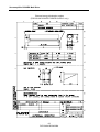
3.5.5 Inductors for long cable lengths with axis motor
Selection : see § 3.4.3.2.
Dimensions see drawing FELX 302983 (see following pages).
61
PVD 3464 GB 04/2004
Servoamplifier DIGIVEX Multi Drive
External energy dissipation resistor
(FOR 25 KW DIGIVEX POWER SUPPLY only)
62
PVD 3464 GB 04/2004
Servoamplifier DIGIVEX Multi Drive
63
PVD 3464 GB 04/2004
Servoamplifier DIGIVEX Multi Drive
4. PARAMETER FUNCTION AND
ADJUSTMENT
4.1 DIGIVEX Power Supply
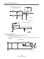
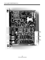
4.1.1 Straps positions
ST1 : No phase detection.
• fitted, no phase detection.
• removed, no detect. Single-phase operation at 20% of maximum capacity.
ST2 : Regeneration cycle. See §1.4.3. Strap ST2 is not fitted on 12 kW Power Supplies.
ST3 : Power bus discharge.
• between 1 & 2, bus discharged via regeneration resistor if bus voltage falls below
200V. With this option the bus discharging time can be higher than 5 seconds.
•
between 2 & 3, bus discharged upon supply cut out (no mains supply detection).
Approximately 100 ms after motors stop.
Standard configuration: ST1 and ST2 fitted, ST3 between 2 and 3.
Location : See next page.
64
PVD 3464 GB 04/2004
Servoamplifier DIGIVEX Multi Drive
ST3
ST2
ST1
65
PVD 3464 GB 04/2004
Servoamplifier DIGIVEX Multi Drive
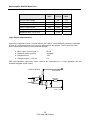
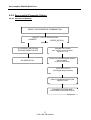
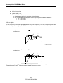
4.1.2 Initialization Sequence
Upon energizing :
•
T0
← Mains present
•
T0 + 100 ms
→ OK relay closed
•
T0 + 700 ms
→ Main switch closed capacitors precharged
•
T0 + 800 ms
→ Regeneration test OK
•
T0 + 940 ms
→ INIT signal
The INIT. (initialization) signal enables the drives to be released.
4.2 DIGIVEX Drive
4.2.1 Functions
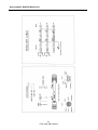
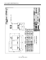
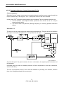
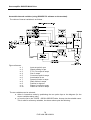
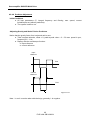
4.2.1.1 Block Diagram
See next pages
It groups the main drive functions and adjustment parameters.
• On the right, the motor - resolver - power unit
Parameters can be set for :
⇒ motor selection, which dictates drive calibre
⇒ general resolver characteristics.
The choice of the motor - drive combination automatically determines certain parameters: current
limitation, protection I2 = f(t), servo control parameters.
•
Ahead of current control
♦ Second order filter for reducing resonance effects at high frequencies
♦ External reduction of current limitation.
•
Resolver digital processing (non parametrable) and the optional encoder emulation
function (number of points adjustable from 1 to 16,384).
66
PVD 3464 GB 04/2004
Servoamplifier DIGIVEX Multi Drive
•
Speed loop unit, where the following parameters can be set :
⇒ maximum speed for the application (limited by the motor max. speed).
⇒ scaling (1 V = N rpm.).
⇒ choice of corrector type - proportional, proportional and integral, proportional and
double integration, or simply choice of current regulation operation.
•
Predictive action related to speed control
These actions, outside the speed loop, directly affect the torque level. As they are outside, they
have little effect on loop stability. Conversely, they allow anticipated action, without waiting for
speed loop reaction.
These predictive actions (or predictors) are :
⇒ Gravity : compensation of vertical masses.
⇒ Dry friction : a friction value is set a priori, the corresponding torque reference is
applied, its sign being that of the speed reference.
⇒ Viscous friction: compensation of friction proportional to speed (hydraulic or electrical
system drive).
⇒ - Acceleration : changes in the speed reference (drift) are monitored and action is
taken directly on the torque reference via a coefficient K, image of inertia values.
•
Analogue input speed reference (16 bits), non assignable.
•
On the left of the block diagram, the logic and analogue inputs/outputs.
The parameter setting software is used for :
⇒ assigning certain of these inputs/outputs
⇒ forcing them to a logic state. The inputs are then disconnected from the outside.
67
PVD 3464 GB 04/2004
Servoamplifier DIGIVEX Multi Drive
68
PVD 3464 GB 04/2004
Servoamplifier DIGIVEX Multi Drive
4.2.1.2 Logic Input Forcing
The software (or.through handed terminal) can be used to force a logic input to a particular value.
Using the software, the CW (zero speed clockwise), CCW (counter clockwise) and T (zero
torque) inputs may be
• disconnected from the physical input
• forced by software to 0 or 1 (HIGH or LOW).
4.2.1.3 Stimulus/Oscilloscope Function
Functions integrated in the drive can be used to excite the speed or torque reference: dc voltage,
square (response to scale), sine, noise.
These stimuli may be activated by a PC (or by the terminal). The result, stored in the drive, may
be displayed on the PC screen by using the oscilloscope function (or sent to the 2 analog
outputs).
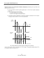
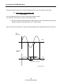
4.2.1.4 Logic outputs
1) Speed detection
The two outputs assigned OUT1 and OUT2 are used to detect four speed ranges depending on
the logic state.
OUT1
OUT2
SPEED
1
0
1
1
Speed ≤ 48 rpm
Speed ≤ N1
1
0
Speed ≤ N2
0
0
Speed > N2
N1 and N2 are speeds that are programmed in the parameters.
N2 > N1
and N1 > 48 rpm.
2) Speed reached and anchored
Selection and assignment with PME DIGIVEX PC software (PVD 3483) or terminal DTP001
(PVD 3491)
4.2.1.5 Brake Action
The drive can be declared in the parameters with a brake function.
The 24 V brake supply to the DIGIVEX Power Supply (terminal block X1) is monitored by the
drive.
CAUTION: cutting this supply releases brakes on all axes.
69
PVD 3464 GB 04/2004
Servoamplifier DIGIVEX Multi Drive
•
•
24 V present: Axis under torque. Removal of limitation to 90% of rated motor current.
24 V absent: Axis at 90% reduced torque of rated motor current.
The brake engage or release order is in no event given by the drive but by the machinery
automatism. The automatism can monitor the drive outputs indicating zero speed to decide
whether or not to apply the brake.
4.2.1.6 Emergency Stop (speed loop mode only)
This signal is applied to theDIGIVEX Power Supply, terminal block X3 between terminals 8 and
9. During normal operation, it should be at logic state 1 (24 V on terminal X3-8).
If the signal goes LOW, this causes :
• All drives set to zero speed without ramps;
• Holding under torque after stoppage.
4.2.2 Servocontrol and Adjustment Parameters
4.2.2.1 List of Parameters
Choice of type of regulation :
• Speed Proportional P
⇒ Proportional integral PI
⇒ Proportional double integral PI²
• Current regulation
In all cases :
• Filtering frequency
• Offset
• Current limitation
Minimum Value
20 Hz
- 1 % V max.
0A
Maximum Value
800 Hz
+ 1 % V max.
Drive I pulse
In speed regulation (P, PI, PI²)
• Max. Speed
100 rpm
100,000 rpm
• Speed for 1 Volt
10 rpm
20,000 rpm
• Proportional gain
Drive Ipulse/156
Drive Ipulse x 210
• Integration frequency stop
0,1 Hz
150 Hz
• Speed 1 and speed 2
48 rpm < speed 1 < speed 2 < max speed
• Predictors (gravity, static or dynamic friction, acceleration)
70
PVD 3464 GB 04/2004
Servoamplifier DIGIVEX Multi Drive
4.2.2.2 Regulation Selection: Current, Proportional, Pl, Pl≤
Current regulation
Selecting "current" means current can be controlled directly (therefore motor torque through the
torque coefficient Kt). This the gives 10 V = peak pulse current of the drive selected.
In this mode, PI/PI2 adjustment and predictors are neutralised. The only operative features are :
• Current limitation (often adjusted below permanent drive current so as not to trip in
mean and rms values)
• The second order low pass filter (filtering frequency) for reducing possible resonance
effects.
Selection of P
The drive is used in speed loop mode with purely proportional gain. This gain is the ratio between
the output current and the speed error. It is expressed in mA / rpm.
Dipl17gb.D/pl32.W
At speed N equal if the gain increases, the error e decreases, the system speed increases and
its bandwidth.
Increased gain may lead to instability because of other components in the loop (resonance,
second order filter).
The use of proportional action P alone has the drawback of providing zero stiffness, because
there is no integration ahead of the current part.
71
PVD 3464 GB 04/2004
Servoamplifier DIGIVEX Multi Drive
Dipl17gb.D/pl33.W
Thus, if a torque jog is introduced when stopped there will be a permanent speed error (related in
particular to gain P) and the system will run as long as the torque is present.
Notice that in modes P, PI and PI2 all of the predictors are validated.
PI Selection (proportional and integral action)
By comparison with P alone, PI provides the following two changes :
• Gain (open loop) at zero frequency is infinite; if there is a torque jog there will be an
angular discrepancy of the motor shaft relative to the rest state. This angle will be
proportional to the torque applied and there will be no permanent speed drift. It is then
possible to speak of "rigidity" of the system. This rigidity is strictly proportional to the
integration stop frequency.
•
Proportional gain P fixes the bandwidth f0 (system speed). Integral action entails a -90°
phase shift, which generates instability. This phase shift is not troublesome at low
frequencies but may make the system unstable at higher frequencies. The "integral
stop frequency" should therefore be correctly adjusted (0.2 - 0.3 times the bandwidth
f0).
72
PVD 3464 GB 04/2004
Servoamplifier DIGIVEX Multi Drive
PI2 Selection (proportional and double integration action)
By comparison with P alone, PI2 brings about the following two changes :
• Rigidity at rest is infinite. Upon a motor torque jog and after a transient period, the
motor shaft returns to its rest position (there is no permanent position discrepancy).
• The double integral action entails a - 180° phase shift at low frequencies. Poor integral
stop frequency setting may make the system unstable. It should be limited to 0.1 - 0.2
times the bandwidth f0.
4.2.2.3 Integration Stop
See the previous paragraph for the role of this parameter. The definition from Bode curves only is
given below (gain / frequency and phase / frequency)
Dipl17gb.D/pl34.W
4.2.2.4 Speed Scaling
The choice of motor-drive unit fixes a maximum possible speed.
The "maximum" speed parameter can be used to reduce this maximum speed for the application.
This parameter is external to the speed loop and changing it does not alter the gain.
The "speed for 1 Volt" parameter fixes the speed "gradient" (e.g. the maximum speed can be
obtained for 10V, 9V or 7V depending on the positioning control).
73
PVD 3464 GB 04/2004
Servoamplifier DIGIVEX Multi Drive
4.2.2.5 Filtering Frequency
Resonance
Many system have one or more resonance frequencies related usually to mechanical
phenomena: inertia or masses, related to the stiffness of the mechanical components (belts,
screws, gears, frames, etc.).
In reduced frequency areas around the resonance frequency there are :
• large variations in loop gain
• large variations in phase in closed loop mode
This leads to instability or "squealing", more-or-less violent oscillations.
Second Order Filter
This phenomenon cannot be treated by adjusting P/PI/PI2. If the resonance cannot be dealt with
mechanically, the frequencies concerned must be eliminated. This is the job of the 2nd order low
pass filter.
Diggb17.D/pl35.W
Resonance frequencies are usually higher than 50 or 60 Hz (whereas oscillations from incorrect
PI or PI2 settings are generally lower than 50 Hz).
4.2.2.6 Predictors
Purpose of Predictors
Four physical phenomena :
• vertical mass
• dry friction
• friction proportional to speed
• acceleration
are direct and calculable cause of changes in motor torque.
74
PVD 3464 GB 04/2004
Servoamplifier DIGIVEX Multi Drive
Predictors are intended, by calculation, to act directly on the current reference without going
through the speed loop and without waiting for the speed error caused by these phenomena (see
block diagram).
The principle for adjusting and working on the predictors is to minimise the part of the current
reference from the P, PI, PI² branch and therefore to reduce the speed error.
As these predictors are outside the speed loop (which must be set first) they do not affect
stability. They considerably improve response time.
The acceleration predictor improves stability and can be used to increase the gain of any position
loop superimposed on the speed loop.
However, it should be noted that a number of speed servo controls do not require the use of
these predictors.
General characteristics of each predictor
• Mass or gravity compensation (vertical axis)
The current value in Amps required by the motor to move the mass at constant speed (mean
between rise and fall) is introduced directly in the parameter.
•
Dry or "static" friction
The friction force is fixed whatever the speed. The direction is opposed to movement, the sign
depends therefore on the speed reference sign.
In this case too the value of the current in amps required for the motor to overcome friction is
entered directly.
The limit expressed in revolutions per minute defines the speed range in which compensation is
zero.
Dipl17gb.D/pl36.W
The limit is in the order of 1/1000th of maximum speed. This zone is used to reduce torque
oscillation during rapid and repeated changes of the speed sign. This is particularly the case at
rest when there is a position loop.
75
PVD 3464 GB 04/2004
Servoamplifier DIGIVEX Multi Drive
•
Dynamic" Friction Compensation
This is friction proportional to speed encountered on certain mechanical items using fluids.
Value to enter : coefficient in amps (rpm)
•
Acceleration Prediction
Depending on the total inertia (load and motor rotor) and of the desired acceleration, the
necessary torque is equal to C = ΣJ. dω/dt.
The change in the reference speed is monitored to send a reference proportional to inertia (fixed)
and acceleration to the current control. This illustrates a limitation of the system; there is no point
in having a speed reference that changes more than maximum possible motor acceleration given
by dw/dt = peak torque /ΣJ. Acceleration prediction is only worthwhile if the reference speed
features a ramp.
The parameter used is tpr, prediction time in milliseconds; tpr ranges from :
⇒ 0 ms (no prediction)
⇒ t = td, starting time from 0 to maximum speed, with full drive current. There is then
100% correction.
4.2.3 Entering Parameters / personnalization board/change
Customisation parameters for the motor-drive unit are introduced at start up using a PC under
Windows via the DIGIVEX PC software (see brochure PVD 3483 DIGIVEX P.C SOFTWARE).
They may be read and in part altered via the display/parameter setting terminal. (see DIGIVEX PC
SOFTWARE instructions PVD 3483 F).
The characterization is safeguarded in an EEPROM store mounted on a plug-in sub-print. This
store can therefore be transferred from one drive to another of the same calibre.
Transfer of data from this EEPROM to a servoamplifier of different rating generates a fault. The
parameters stored in the EEPROM are retained.
Access to parameters may be restricted by an access code also stored in the EEPROM store
(see DIGIVEX PC SOFTWARE instructions PVD 3483 F).
Customization unit reference : SZ6608B
• With a short circuit on Jo for spindle motors
•
With an open circuit on Jo for axis motors
•
•
•
Motor name
Speed reference value
Adjustment number.
Label :
76
PVD 3464 GB 04/2004
Servoamplifier DIGIVEX Multi Drive
4.2.4 Servocontrol Parameter Setting
4.2.4.1 Overview of Settings
SELECT MOTOR/DRIVE COMBINATION
SELECT TYPE OF REGULATION
CURRENT
SPEED (P/PI/PI≤)
Ifc CURRENT LIMITATION,
SECOND ORDER FILTER
NO PREDICTOR
POSSIBLE SETTINGS
Max. Speed, Current limitation,
Speed for 1 Volt
FILTER fc & PROPORTIONAL GAIN P
ADJUSTMENT
(suppress resonance)
ENTER PI OR PI≤
Set integral stop frequency
GRAVITY AND DRY FRICTION
PREDICTORS
DYNAMIC FRICTION AND
ACCELERATION PREDICTORS
Dipl40gb.D/W
77
PVD 3464 GB 04/2004
Servoamplifier DIGIVEX Multi Drive
4.2.4.2 Parameters setting Tools
•
Without PC software or terminal
There is no access to setting changes. It is possible only to display the two variables assigned to
the two analogue outputs on a standard oscilloscope. These are usually :
♦ Output 1 : speed measurement,
♦ Output 2 : current set point.
•
With the terminal, without PC software
If the system allows complete access (level 2), the terminal provides access to the servo-control
parameters (regulation type, gain, etc.). Two types of display are available :
♦ either by direct read-out on the LCD display of :
input set point
current set point
bus voltage
temperature
speed measurement
♦ or by assigning two of the 5 internal variables :
input set point in rpm
speed reading in rpm
current set point in A
bus voltage in V
position in degrees
to the two analog outputs and using an external oscilloscope.
If at level 1, it is possible only to modify the gain already in place (ratio 0.7 to 1.4), speed for a set
point of 10V (±10% unless already at maximum speed) and offset (±1%).
•
With the DIGIVEX PC Software
Three tools can be accessed :
♦ Generation of speed set point (fixed, scale, sine) of which the amplitude,
frequency, and mean value are adjustable.
♦ Oscilloscope function, for displaying and recording the response curves of any
two of the internal variables available.
♦ Adjustment procedure, using the above two functions, ("parameters" window
open) and using a wave to make the adjustment (except for predictors) from the
single scale response.
78
PVD 3464 GB 04/2004
Servoamplifier DIGIVEX Multi Drive
Accessible internal variables (using DIGIVEX PC software or the terminal).
The choice of internal variables is as follows :
Dibl1gb.Ds4/W
Figure reference
♦
♦
♦
♦
♦
♦
♦
♦
♦
♦
♦
1
2
3
4
5
6
7
8
9
Iu
Iw
Input set point in rpm
Speed reading in rpm
P, PI, PI≤ output in amps
Sum in amps
Current set point in amps
Acceleration in ms
Dynamic friction in amps
Static friction in amps
Position in degrees
Phase U current in amps
Phase W current in amps
The two variables can be selected :
• either in interactive mode by positioning the two probe tips on the diagram (for the
eleven variables above only)
• or from the list in the TOOLS - OSCILLOSCOPE table. Access via the variable name.
This is valid for all twenty variables, the eleven above plus the following :
79
PVD 3464 GB 04/2004
Servoamplifier DIGIVEX Multi Drive
♦ Low frequency generator (stimuli)
♦ Temperature in degrees C
♦ Bus voltage in volts
♦ Id set point in amps
♦ Iq set point in amps
♦ Id measurement in amps
♦ Iq measurement in amps
♦ Voltage Ud in Volts
♦ Voltage Uq in Volts
♦ Auxiliary input in Volts
Notice that these twenty variables can be assigned to the two analogue outputs, that allows
eventually to use an external oscilloscope.
4.2.4.3 Parameter Access Condition
Access levels
• Level 1 is permanently accessible and can be used to modify :
♦ proportional gain within bounds (0.7 - 1,4)
♦ speed for 1 V reference (±10%) and maximum speed (unless already at max.
speed).
♦ offset.
It can also be used for reading all parameters.
• Level 2 is accessible by entering a password and is used for altering all the
parameters as required for the application.
This level can be used on line or off line with the PC software or the terminal.
The access code is stored in EEPROM, as a parameter.
Off Line Mode
If working at level 2 and with the PC software, off line mode can be used for preparing complete
parameter files: motor selection, servocontrol parameters, inputs and outputs, etc. This is data
processing work on files (File, Open, Save as …).
On Line Mode (with level 2 access)
In this mode the RS 232 link connects the PC with its software and the DIGIVEX DRIVE (see
DIGIVEX PC software instructions).
When going on line all the parameters in the drive are copied to the PC. Any parameter altered by
the PC will be copied back to the drive.
80
PVD 3464 GB 04/2004
Servoamplifier DIGIVEX Multi Drive
On line mode has the following features :
• resolver parameters cannot be modified
• loop parameters can only be modified by the + or - keys, as numerical values cannot
be keyed in directly
• if a complete parameter file is to be sent via the serial link (first time loading, copying
from one drive to another) :
• the torque set to 0 (T = 0) by software during the transfer. After transfet the torque
must be reset to 1 by forcing the input T = 0. (see DIGIVEX PC software instructions
PVD 3483 F).
• the drive checks compatibility with the drive calibre. It may reject the file if
incompatible.
4.2.4.4 Motor Selection and Parameter Entry via DIGIVEX PC Software
See DIGIVEX PC software instructions PVD 3483 F
• Calibre selection
• Motor selection (standard or special)
• Resolver selection
• Entering servocontrol parameters (global transfer)
• Assigning inputs/outputs and variables
• Using the oscilloscope function
• Two parameters set : "Extended parameter set" option
4.2.4.5 Loop Parameter Adjustment Speed Regulation Mode
Speed for 1 V and maximum speed
Maximum possible speed is fixed by the choice of motor/drive combination. It can be reduced
only.
To check the result :
• select a "continuous" set point of say 1 V
• Use "Drive Status" (COMMANDS menu) to check the value obtained for the "speed
measurement in rpm" variable.
Proportional Gain Setting
Initial status :
• Change to proportional gain P only
• Filtering frequency fc to maximum (800 Hz) and low gain
• System able to run, no predictor.
The P gain and filter frequency adjustments are simultaneous. If, when increasing P gain, the
system starts to resonate, this can be suppressed by reducing the filter frequency and then
increasing P, etc. until a compromise is reached.
81
PVD 3464 GB 04/2004
Servoamplifier DIGIVEX Multi Drive
Maximum advised value for P
There is a maximum recommended proportional gain depending on drive gain and corresponding
to maximum current ripple.
CALIBRE
P in mA / rpm
2/4
35
4/8
75
8 /16
150
16 / 32
300
32 / 64
600
NB: this value may be exceeded under certain conditions. Please ask for details.
Generate a speed set point step (for instance, 5% of maximum speed)
Display the oscilloscope function
•
•
•
Channel 1 ⇒ input reference.
Channel 2 ⇒ speed reading.
Trigger on the set point (channel 1), rising flank, 1 to 2% of maximum speed.
Increase gain P
Excite the stimulus in on line mode. The response at one speed reference scale is obtained.
Three cases may arise :
Non oscillating response
82
PVD 3464 GB 04/2004
Servoamplifier DIGIVEX Multi Drive
A response must be achieved without overshoot and oscillation. For example, increase gain until
oscillations appear progressively; then reduce it again by 20 - 30%.
If the maximum value shown in the table is reached with P gain without having reduced filter
frequency, then :
• stop increasing P,
• reduce the filter frequency to the oscillation limit.
Filter frequency adjustment
Oscillations may arise on the response achieved above (even during the increase in speed).
Response with pseudo-oscillation
Resonance occurs here (probably of mechanical origin) of frequency fr = 1/T, more than 100 Hz.
Reduce the filtering frequency until the oscillation almost vanishes. If impossible maximum gain
is attained
If possible gain may be increased again until a response with no oscillation is obtained.
Oscillation may appear again, if so reduce the filtering frequency slightly.
Notice that it is essentially P and the filtering frequency that fix the bandwidth.
If the resonance frequency is too low, adjust the filter frequency to a high value.
PI/PI2 - Integral Stop Frequency Setting
Initial status :
• P gain alone. P setting and filtering frequency completed.
• Integration stop frequency = 0.
83
PVD 3464 GB 04/2004
Servoamplifier DIGIVEX Multi Drive
•
•
Still no integration.
System able to run.
♦ Select PI or PI≤.
♦ Use the same stimulus as before (set point step).
♦ On line, increase the integration stop frequency until overshoot of about :
25 - 30% in PI
15 - 20% in PI≤
With no ripple.
If the frequency is too high ripples appear at fairly low frequency (< 50 Hz). Frequency must then
be reduced (never readjust gain P).
Speed
measurement
fi too high
pseudo-period
Time
Dipl43gb.D/45W
Speed
measurement
fi too high
pseudo-period
Time
Do not change PI to PI2 without resetting integral frequency to zero.
84
PVD 3464 GB 04/2004
Dipl43gb.D/46W
Servoamplifier DIGIVEX Multi Drive
4.2.4.6 Predictor Adjustment
Initial Conditions
• All loop parameters (P, integral frequency and filtering, max. speed, current
limitation)are set (without predictors).
• The system is able to run.
Adjusting Gravity and Static Friction Predictors
Notice that the gravity factor for a horizontal axis is zero.
• Take a square stimulus, offset = 0, peak-to-peak value = 3 - 5% max. speed in rpm,
frequency 0.2 - 1 Hz.
• Display with the oscilloscope function :
♦ input reference
♦ current reference
Input
reference
Time
Current
reference
Time
Diggb43.D/47W
Nota : I+ and I- must be taken with their sign, generally I- is negative.
85
PVD 3464 GB 04/2004
Servoamplifier DIGIVEX Multi Drive
In principle :
I+ + I−
in amps (horizontal movement, gravity = 0).
2
I −I
• Static friction = + - in amps.
2
•
Gravity =
•
•
•
Enter these values in the parameters.
Enter the threshold value (e.g. threshold = max. speed / 1000).
After entering the values, the same stimulus can be used for checking the result
obtained.
Display the input reference on one channel and the P, PI, PI2 output on the other
channel. The result should be similar to that shown below:
•
P, PI, PI≤
Output
Time
Dipl43gb.D/49W
86
PVD 3464 GB 04/2004
Servoamplifier DIGIVEX Multi Drive
Dynamic Friction and Acceleration Predictor Adjustment (Assuming the dry friction and
gravity parameters are set)
•
•
•
Use a sine stimulus, offset 0, peak-to-peak value 10 - 20% of max. speed, frequency
0.2 - 1 Hz.
With the oscilloscope function display :
♦ the input reference on one channel
♦ the P, PI, PI² output on the other channel.
Acceleration predictor adjustment. Increase the predictor to minimise P, PI, PI² output.
Too high a value increase P, PI, PI≤ with a phase shift.
Input
reference
Time
P, PI, PI≤
Output
Predictor too weak
or zero
Maximum positive
acceleration
Predictor
too high
Time
Predictor correctly
adjusted
Dipl43gb.D/49W
Very marked difference between optimum setting and no predictor.
Correct setting gives minimum amplitude to P, PI, PI² output. The predictor should reduce P, PI,
PI² output by a ratio of at least 5 to 10.
87
PVD 3464 GB 04/2004
Servoamplifier DIGIVEX Multi Drive
Remember that the value (in ms) of tpr (prediction time) is close to td (start up time) with :
td = (Load inertia + motor inertia).ω max
max. torque
td is acceleration time from 0 to max. speed with maximum torque
td in seconds, inertia in kgm2, wmax. in rd/s, torque in Nm
•
Dynamic friction predictor adjustment. After setting all the other predictors increase the
dynamic predictor to minimise the P, PI, PI2 output signal.
When correctly set the minimum output should be obtained and in phase with the input reference.
Input
reference
Time
P, PI, PI≤
Output
Time
Minimum value
Dipl43gb.D/50W
88
PVD 3464 GB 04/2004
Servoamplifier DIGIVEX Multi Drive
4.2.4.7 Parameter Adjustment in Current Regulation Mode
If the "current" option is selected, the following items only are to be adjusted :
• current limitation. Take care with this type of application not to trigger upon monitoring
of mean current and rms current. Often current limitation = permanent current.
• Second order filter frequency. This can only be done with the "upper" regulation loop
providing the current reference.
4.2.4.8 Other Parameters
Logic and Analogue Inputs/Outputs
Access either via the menus (COMMANDS + INPUT ASSIGNMENT) or (COMMAND +
OUTPUTS ASSIGNMENT) or in interactive mode by clicking on the I/O at the left of the block
diagram. This makes it possible to :
•
•
Assign one of the twenty internal variables to each of the two analogue outputs one of
the internal variables.
Force the logic inputs to 0 or 1 (HIGH or LOW).
The logic inputs/outputs are assigned on a permanent basis.
Encoder Emulation Option
• Choice of number of marks from 1 to 16,384 per revolution (off line.
• Validation of zero signal in teach mode (on line).
Miscellaneous Choices
• Choice of processing strategy for monitoring in mean and rms currents: current
reduction or power cut-out (see § 3 and DIGIVEX PC software instructions).
• Choice of brake use strategy : current reduction or not when brake is applied (see
DIGIVEX PC software instructions).
• Choice of motor thermal protection strategy (with or without thermal protection).
89
PVD 3464 GB 04/2004
Servoamplifier DIGIVEX Multi Drive
5. STARTING UP - DETECTING CAUSES OF
STOPPAGE
5.1 Start Up Sequence
5.1.1 Prior Checks
Wiring Check
•
•
•
•
•
•
Power and auxiliary connections to DIGIVEX POWER SUPPLY. See wiring diagram
(see § 3.2, 3.3).
Connection of any external energy recovery resistor and presence or absence of strap
on terminal block B3 (see § 4.1).
Wiring of Reset and Emergency Stop to DIGIVEX POWER SUPPLY (see § 3.3).
External arrival of 24 V source for motor brake on DIGIVEX POWER SUPPLY terminal
block X1.
Check resolver connections (see § 3.3.3.4) :
♦ at motor end
♦ at DIGIVEX DRIVE end.
Check the power, brake and thermal sensor connections (see § 3.4.3.3) :
♦ at motor end
♦ at DIGIVEX DRIVE end.
Power Supply Type Check
•
•
•
Power : 50/60 Hz, three-phase 400 V ± 10%.
Auxiliaries : single-phase, 50/60 Hz, 400 V ± 10%.
Brake supply : 24 V dc ± 10% (ripple included).
Check the position of the DIGIVEX POWER SUPPLY straps (ST1 / ST2 / ST3, see § 4.1.1).
Warning: Before any work make sure that the power bus is at 0 V. Wait at least three minutes
after the motors have come to a complete stop before carrying out any work. The power and
auxiliary buses must be at zero Volts when removing the drives from the rack, all the
LEDs are switched off.
90
PVD 3464 GB 04/2004
Servoamplifier DIGIVEX Multi Drive
5.1.2 First Time Starting with DIGIVEX PC Software or the terminal
This is done drive by drive. First remove (or disconnect) drives that have not yet been set.
•
•
•
•
•
So as not to supply power, remove terminal block X2 from the DIGIVEX POWER
SUPPLY module. This prevents the main switch from closing.
Connect the PC via the RS 232 serial link.
Supply the (low level) auxiliary part only. This can only be done by drawing the 400 V
single phase auxiliary supply from ahead of the main switch. The « Power Off » led of
the DIGIVEX POWER SUPPLY lights up.
Check that the rack fans work (airflow).
Use the PC (Connection menu) to come on line, If the system does not come on line :
♦ Check the serial link configuration is compatible.
♦ Check the cable.
When the system is on line all the parameters in the DIGIVEX DRIVE can be read.
• The DRIVE FAULT LED is on (no power). Use the PC (or the terminal) to check if
there is no fault (COMMANDS + FAULTS menu). See possible diagnostics.
• If access to modification is prohibited (level 1), read the parameters in the drive and
check they comply with the problem: motor type, maximum speed, etc.
• If access to modification is allowed (level 2) the configure the drive. This may be done
off line in a file which is then transferred or modified ON LINE.
♦ Motor selection.
♦ Speed or torque loop parameters selection (note that without power, it is not
possible to check if these parameters are correct).
♦ Auxiliary selections: validate brakes, analogue outputs, safety strategies, etc.
• Cut off the auxiliary supply. Replace the DIGIVEX POWER SUPPLY terminal block X2
(OK and READY relays).
Restore the low-level supply. Use the software to force the drive to zero torque.
• Power up. Normally the POWER ON LED of the DIGIVEX POWER SUPPLY lights. If
there is a drive fault the DRIVE FAULT light comes on. Read the diagnostic and
correct the fault.
If all is in order, check the brake (if fitted) works properly.
•
•
Remove the "zero torque" lock with the software or by the hardware contact (set "T=0"
input to 24V), open any brake.
Adjust the system using the stimuli (PC software or terminal)
♦ "Direct current" stimuli (square with peak-to-peak = 0). Check Nmax.
♦ "Square" stimuli or adjustment procedure to set the servo-control parameters.
♦ DIGIVEX PC software to set the predictors, if necessary.
For all these manipulations, make sure that the driven mechanism can run freely.
91
PVD 3464 GB 04/2004
Servoamplifier DIGIVEX Multi Drive
5.1.3 Start up or Modification with the Display / Parameter Setting
Terminal / Parameters transfer
The general process is the same as above.
The display / parameter setting terminal is for systems that have already been programmed :
• either by PC software
• or by transfer of parameters from one drive to another using the PC software or the
terminal
• or by physically transferring the EEPROM containing the customised application. See
§ 4.2.3.
5.2 Detecting causes of stoppage
5.2.1 DIGIVEX Power Supply
The following LEDs are located on the front panel :
LED
COLOUR
PURPOSE
Main and auxiliary power present, no supply or drive
faults
POWER ON
Green
POWER OFF
Red
RECOVERY
Red
DRIVE FAULT
Red
- Fault with drive
DC
OVERVOLT.
Red
Excess bus voltage (>750 V)
Red
Mains overvoltage (Urms > 470 V)
Red
Mains phase absent
Red
Dissipater temperature > 85°C
AC
OVERVOLT.
PHASE
OVER TEMP
No power or supply fault
- Either lights temporarily for normal use of regeneration
resistor
- Or if permanently on, regeneration fault
. No resistor or short circuit
. Internal resistor thermal sensor tripped
92
PVD 3464 GB 04/2004
Servoamplifier DIGIVEX Multi Drive
5.2.2 DIGIVEX Drive
5.2.2.1 Display
Problems that arise may be displayed in three ways :
• On the front panel of the DIGIVEX POWER SUPPLY module, a DRIVE FAULT LED
indicates problems with any of the drives.
•
On the front panel of each DIGIVEX DRIVE module, two RUN and FAULT LEDs
indicate the overall status of the drive.
♦ « RUN » is green, everything is in order.
♦ « RUN » off and « FAULT » on, no CPU activity (incorrect).
♦ « FAULT » flashes, decreased drive performance without cutting the rack out.
♦ « FAULT » is permanently on, major fault opening the power supply OK relay
and therefore the main switch.
♦ « RUN » and FAULT off, low-level supply to drive failure
•
To identify the exact nature of the problem or the drive status, requires :
♦ either the DIGIVEX PC software, which specifies the problem and hints for
correction in plain language
♦ or the display/parameter terminal which displays in plain language a code for
each problem encountered.
5.2.2.2 Drive Fault Processing
Four cases may arise :
Fault
These faults entail :
• DIGIVEX Drive FAULT LED comes on.
• power supply DRIVE FAULT LED lights and consequently the main switch opens and
the power is switched off.
• The fault origin code is stored in the drive.
Systematic reduction in performances (with no choice of strategy)
This is the case with dissipater temperature monitoring. In this case :
• Internal alteration of maximum permissible mean current, the FAULT LED flashes.
Storage of the condition in the drive.
• No action on the DIGIVEX Power Supply module.
93
PVD 3464 GB 04/2004
Servoamplifier DIGIVEX Multi Drive
Choice of strategy
For current monitoring, when customising the drive, there is a choice between :
• Strategy 1: Fault.
• Strategy 2: Performance reduction without storage in drive as a fault condition.
Central Processing Unit Fault
This fault causes the green RUN LED to go out (and the red FAULT LED to light).
5.2.2.3 Current Monitoring
Drive mean current
To prevent excessive overheating of the drive the mean current [I = f(t)] is compared after about
two seconds filtering with the permanent permissible current (rating).
There is then a choice between two strategies:
• Strategy 1: Fault with opening of the power supply OK relay and the main switch
• Strategy 2: Reduction of the permanent drive current to 90% of the permanent
permissible current. The FAULT LED flashes.
Motor rms current
To prevent the motor being tripped by the thermal sensor, the drive monitors the rms current
[I2 = f(t)].
The rms current is compared with the permanent permissible current under slow rotation by the
motor Î0 (after first order filtering with 20 sec time constant). This data is characteristic of the
motor and is known to the drive when the motor-drive selection is made.
As before, there is a choice of two strategies :
• Strategy 1: fault
• Strategy 2: reduction of drive pulse current to 0.9 Î0 motor. The FAULT LED flashes.
Drive output current
Two features are monitored :
• Protection against short circuits: Current derivative monitoring.
• Excessive output current (max. I): checks whether the measured current exceeds the
drive pulse current by 30%.
In both cases the fault is tripped.
Drive input current
Fuse protection in the event of an internal short circuit. Blowing the fuse (bus voltage present,
zero voltage in drive) produces a fault.
94
PVD 3464 GB 04/2004
Servoamplifier DIGIVEX Multi Drive
5.2.2.4 Temperature Monitoring
DIGIVEX Drive dissipator temperature
• If the dissipater temperature is less than 60°C nothing happens.
• From 60° to 85°C the pulse current that the drive can deliver is reduced (the FAULT
LED flashes slowly).
• At 95°C fault tripped.
Servomotor winding temperature
Each HX, HS and HD motor has a thermal sensor. When customizing the drive, this sensor must
be taken into consideration. In this case, excessive motor temperature causes a fault condition.
Ambient temperature
Measured between electronic boards. It stops operation at more than 60°C.
5.2.2.5 Miscellaneous Monitoring
No resolver
Resolver fault or wiring fault.
Overspeed
Speed > 1.15 times the maximum motor/drive speed setting.
These two cases produce a fault with :
• red FAULT LED lights.
Zero bus voltage
This situation may be produced by simply switching off the power (with no fault) or by a power
supply fault.
If the loss of power is not caused by a drive fault :
• the RUN LED remains on;
• the FAULT LED remains off.
95
PVD 3464 GB 04/2004
Servoamplifier DIGIVEX Multi Drive
5.2.2.6 Fault and Diagnostic Summary Chart
: LED on, E=LED off, RF=rapid flashing, SF=slow flashing
FAULT
PC SOFTWARE
PROGRAMMIN
LED
FAULT-FINDING
G CONSOLE
(Red)
FAULT-FINDING
Overcurrent
Max. drive
current reached
Short circuit
dI/dT fault
RUN
LED
(Green)
Excessive mean
current
Excessive rms
current
Output or earth short circuit
Too much current asked of drive
I average fault
I RMS fault
Excessive motor
temperature
Excessive dissipater
temperature
Excessive ambient
temperature
Resolver fault
Excessive speed
Motor overtemp.
Too much current asked of drive. Cycle
too demanding.
Cycle too demanding or no motor fan
cooling
Fin overtemp.
Fan cooling stopped or excessive
cabinet temperature
Problem with resolver or wiring
Ambient
overtemp.
Resolver fault
Speed reference > 10 V
or speed parameter setting error
Overspeed
CPU fault
E
COMMENTS
CPU fault
Bus overvoltage
Bus overvoltage
Regenerative braking impossible.
Disconnected from mains supply.
Customization card incompatible with drive
rating or drive type
☼
☼
☼
☼
☼
☼
☼
☼
E
E
Liaison impossible
RUN
LED
(Green)
FAULT
LED
(Red)
PC SOFTWARE
FAULT-FINDING
RF
Excessive mean
current OR
Current reduction.
I mean > drive rating
RF
Excessive rms
Current
Excessive dissipater
temperature
Current reduction.
Drive RMS current > Îo motor
SF
Customization card
fault
EEPROM fault
Drive-spindle definition SPINDLE
BIT DEF.
Motor not connected
Control type (drive-spindle) incompatible
with customization cardSZ6608B
MOTOR
Disconnect
Motor wrongly connected
No power supply
PROGRAMMIN
G CONSOLE
FAULT-FINDING
96
PVD 3464 GB 04/2004
COMMENTS
Max. current reduced depending on
temperature
Servoamplifier DIGIVEX Multi Drive
5.2.2.7 Corrective actions
During a start up, the main possible incidents (due to a wrong wiring or to wrong manipulations)
are as follows :
• Resolver fault
♦ Check the resolver connection.
• Overcurrent
♦ Wrong motor connection (incorrect pases U - V - W).
♦ The motor introduced by software is not in accordance with the motor really
connected.
• Overspeed
♦ Wrong maximum speed adjustment.
♦ Software validation of torque loop instead of speed loop.
• Motor is not running and remains without torque
♦ The system is at zero torque (« Hard » or « Soft » input T = 0). The torque has
been assigned at 0 during a global transfer. Activate the torque (see DIGIVEX
PC SOFTWARE instructions or terminal instructions).
♦ The motor is not connected.
• Motor is not running but torque is available
♦ The system is at zero speed, the DIGIVEX Power Supply emergency stop
(EMERGENCY) has no 24V supply.
♦ The CW and CCW inputs are at zero (Hard or Soft) Check with software or
terminal.
5.2.2.8 7-segment display (SS 6611 mounted)
Function: to provide information on DIGIVEX status discriminating between faults. Format:
placed in the upper part of the DIGIVEX.
Description :
Display
0
1
2
3
3 Flashing
4
5
6
7
7 Flashing
8
9
A
F
C
. (dot)
- (dash)
Description
Drive live, no power present
Drive OK, power present
Resolver fault
Excessive ambient temperature or dissipater temperature
Excessive dissipater temperature / current reduction
Excessive speed
Maximum supply current
Maximum drive current reached or di/dt fault
Excessive mean current or excessive rms current
Excessive mean current or excessive rms current: Reduction
Bus overvoltage
Excessive motor temperature
Drive/spindle definition fault
Drive rating incompatible with CUSTOMIZATION
Motor not connected
CPU fault
Unlisted fault
97
PVD 3464 GB 04/2004
Servoamplifier DIGIVEX Multi Drive
6. OPTIONS
6.1 Possible associations
Maximum of two options possible
Integrated encoder
7-segment display
Indexing function
Speed output card
SSI
SERCOS
SC6631
SS6611
SH6601
SV6601
SC6637
SP6605
Association examples:
Integrated
encoder
SC6631
7-segment
display
SS6611
X
Indexing
function
SH6601
X
Speed
output card
SV6601
X
X
SSI
SERCOS
SC6637
SP6605
X
X
Integrated encoder
Integrated encoder
+
OR
+
7-segment display
Indexing function
6.2 Encoder Emulation Card Option (SC 6631)
The resolver is above all a position sensor. It is used to measure the position of the rotor relative to the
stator.
An optional card placed in the upper part of the DIGIVEX Drive regulation card can be used to convert the
signal from the resolver into a string of pulses identical to those from an incremental encoder: A, B, 0, and
their complements.
6.2.1 Resolution and Zero Signal Position Programming
This can be programmed using the DIGIVEX PC software or via the terminal.
The parameter is called up :
•
•
•
either in graphic mode (click twice in the encoder emulation).
or via the menus: Parameters + options.
or by the terminal keyboard.
Resolution
Adjustable from 1 to 16,384 either by the +/- keys or by entering a number directly (OFF LINE only).
Precision
This is provided by the resolver and the conversion electronics.
There is no direct link between precision and resolution, the programmed resolution may be higher than
sensor precision.
Zero Signal Adjustment (not possible with present software)
Adjustment by teach mode, with the PC running "on line".
When the operator judges the position is suitable he confirms it by acknowledging the zero signal.
98
PVD 3464 GB 04/2004
Servoamplifier DIGIVEX Multi Drive
6.2.2 Electrical Characteristics
The electrical output interface meets standard RS 422 for differential serial links. The circuit used
is a Line Drive type MC 26 LS 31 D. The electrical characteristics are therefore closely related to
the use of this component.
Voltage Supply
The encoder emulation cards are galvanically isolated between the output stage via three optocouplers and need to be powered from a +5 V, ±10%, 100 mA external source, as do the
incremental encoders.
In no event can this supply, used only for galvanic insulation, be used to save position
information from the resolver in the event of a break in the drive low levels.
Short Circuit Whitstanding
A single output can be short circuited to 0 V at a given time.
Signal Pattern
Signal levels :
• U high ≥ 2.5V for I high ≥ -20mA
• U low ≤ 0.5V for I low ≤ 20mA
Dipl44gb.D/51W
99
PVD 3464 GB 04/2004
Servoamplifier DIGIVEX Multi Drive
Switching Time
Rise or fall time defined from 10% to 90% of the magnitude in question without cable and without
load.
tr = tf = 45 ns (typical value)
Time Lag between Direct and Complemented Channels
Time lag defined as 50% of magnitudes considered without cable and without load.
-6 ns ≤ ta ≤ 6 ns (maximum)
Time Lag between Channels A, B and Zero Signal
Time lag defined as 50% of magnitudes considered without cable and without load.
-6 ns ≤ td ≤ 6 ns (maximum)
Dipl44gb.D/52W
100
PVD 3464 GB 04/2004
Servoamplifier DIGIVEX Multi Drive
6.2.3 SUB-D Plug
Nine-pin "encoder" Sub-D Plug . Maximum conductor cross-section: 0.5 mm².
PIN
TYPICAL
TASK
1
.
2
Output
Zero signal
3
Output
A
4
Output
B
5
Input
5V
6
Output
Zero signal
7
Output
A
8
Output
B
9
Input
0V
6.2.4 Encoder Emulation Cable (ENCODER terminal block X3)
Cable composed of three 0.14 mm2 twisted pairs, one 0.5 mm2 twisted pair for 5 V supply and
general shielding.
PARVEX SA recommended cable reference CB08307.
Cable may be supplied ready fitted with SUB-D plug, see drawing FELX 304554 (cable
compatible with our CYBER 2000 AND CYBER 4000 NCs).
101
PVD 3464 GB 04/2004
Servoamplifier DIGIVEX Multi Drive
102
PVD 3464 GB 04/2004
Servoamplifier DIGIVEX Multi Drive
DIGIVEX SERVO-AMPLIFIER
Reference
Description
DPS0612
DPS0625
DPS0615
SF_02040
12 kW power supply
25 kW power supply
15 kW power supply with return to mains
Three-phase choke for 15 kW mains supply
DRA3165V23
DRA3165V43
DRA3165R23
DRA3168V23
DRA3168V63
DRA3168R43
+6U rack
+6U rack
+ 6U rack
+ 6U rack
+ 6U rack
+ 6U rack
RE_91001
RE_91002
RE_91020
TL_83085
2000 W 27 ohm external resistor
4500 W 12 ohm external resistor
Pair or wall consoles for resistors
6U 11E stopper
DXD06001
DXD06002
DXD06004
DXD06008
DXD06016
DXD06032
DIGIVEX 1/2 single module
DIGIVEX 4/4 single module
DIGIVEX 4/8 single module
DIGIVEX 8/16 single module
DIGIVEX 16/32 double module
DIGIVEX 32/64 single module
DSD13004
DSD13007
DSD13015
DSD16002
DSD16004
DSD16008
DIGIVEX Single Drive 230V 4/8
DIGIVEX Single Drive 230V 7.5/15
DIGIVEX Single Drive 230V 15/30
DIGIVEX Single Drive 400V 2/4
DIGIVEX Single Drive 400V 4/8
DIGIVEX Single Drive 400V 8/16
DPD16050
DPD16100
DPD16150
DIGIVEX Power Drive 50/80
DIGIVEX Power Drive 100/120
DIGIVEX Power Drive 150
SC_6631
SC_6637-1
SC_6637-2
Encoder emulation
Simplified SSI encoder card
SSI encoder card
DTP001
Programming and parameter setting console
FR_03016
FR_03036
FR_03064
16 A filter (DIGIVEX 12 kW)
36 A filter (DIGIVEX 25 kW and 50/80)
64 A filter (DIGIVEX 100/120)
PVD3464x
DIGIVEX Multiple Drive manual D, E, F, GB
DIGIVEX Single Drive manual
DIGIVEX Power Drive manual D, E, F, GB
SSI D, F board manual
PVD3484x
PVD3488x
x = D German, E Spanish, F French, GB English
103
PVD 3464 GB 04/2004
3 slots, fan, reduced (4/8)
3 slots
3 slots, with external recovery
19" 6 slots, fan, reduced (4/8)
19" 6 slots
6 slots with external recovery
Servoamplifier DIGIVEX Multi Drive
PLUGS AND CABLES FOR DIGIVEX AND HX, HS, HD
Reference
Description
DXDK1
DXDK2
Set of 3 Sub-D connectors for DIGIVEX
Set of 4 Sub-D connectors for DIGIVEX + encoder
emulation
CB_08304
FELX304544R205
I/O cable by metre for DIGIVEX drive
Equipped I/O cable (1 Sub-D) for DIGIVEX drive length 5 m
(1)
Equipped I/O cable (2 Sub-D) for DIGIVEX drive length 5 m
(1)
FELX304544R105
6537P0016
FELX304546R105
Encoder emulation cable for DIGIVEX drive
Equipped encoder emulation cable (2 Sub-D) for
DIGIVEX length 5 m (1)
220065R4621
6537P0001
220049R6105
Motor end resolver cable
Resolver cable by metre
Equipped resolver cable (motor plugs & Sub-D) length
5m (1)
For motors HX3
220065R1610
6537P0019
220049R4905
Size 1 power plug
2
0.5 mm power cable by metre
Equipped power cable - length 5m (1)
For motors HX4, HX6, HS6, HD6, HD6, HS8 and Io < 14 A.
220065R1610
Size 1 power plug
2
6537P0009
1 mm power cable by metre
220049R4205
Equipped power cable - length 5m (1)
For motors HS820EQ ( Io > 14 A)
220065R1611
6537P0010
220049R4305
Size 1 power plug
2
2.5 mm power cable by metre
Equipped power cable - length 5m (1)
For motors HD8, HS9
220065R3611
6537P0010
220049R4805
Size 3 power plug
2
2.5 mm power cable by metre
Equipped power cable - length 5m (1)
For motors HD9 and Io < 60 A
220065R3610
6537P0011
220049R4505
Size 3 power plug
2
6 mm power cable by metre
Equipped power cable - length 5m (1)
For motors H....and Io > 60 A
220065R3610
6537P0012
220049R4605
Size 3 power plug
2
10 mm power cable by metre
Equipped power cable - length 5m (1)
104
PVD 3464 GB 04/2004