1
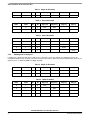
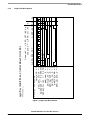
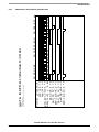
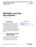
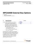
Multiplexed Mode
Muxed Mode
connected Flash
MPC 5200
CS0_b
LP_OE_b
LP_R/W_b
LP_ALE_b
External
Logic
LP_TS_b
IRQ[x]
Optional
Vcc
5.6 k Ω
POR
4
WE_b
OE_b
DQ[7:0]WE_b
DQ[7:0]WE_b
DQ[7:0]
Addr[24:2]
A[22:0]
DQ[7:0]
A[22:0]
Vcc
A[22:0]
A[22:0]
10 kΩ
AD[31:0]
AD[31:24] ↔ Chip 1
AD[23:16] ↔ Chip 2
AD[15:8 ] ↔ Chip 3
AD[7:0] ↔ Chip 4
1
4x
2
4x
AM29LV65
3
4x
AM29LV65
CE_b 32 MByte 4x
AM29LV65
CE_b 32 MByte
OE_b
AM29LV65
CE_b 32 MByte
OE_b
WE_b
CE_b 32 MByte
OE_b
LP_ACK
RY/BY_b
RY/BY_b
RESET_b
RY/BY_b
RESET_b
RY/BY_b
RESET_b
RESET_b
POR Circuit
Figure 11. Multiplexed mode address latching
Figure 11 shows how external logic can be used to interface a bank of four 8-bit Flashed devices using the Muxed Mode.
4.6
Waveforms Snapshots
The following pages contain snapshots of simulation waveforms for the following Local Plus port configurations.
•
Muxed 32-bit XLB read transaction to 32-bit address and 32-bit data port. ALE=1, Wait States= 8, Dead Cycles= 0.
•
Muxed 32-bit XLB write transaction to 32-bit address and 32-bit data port. ALE=1, Wait States= 8, Dead Cycles= 0.
•
Muxed 32-bit XLB read transaction to 32-bit address and 32-bit data port. ALE=1, Wait States= 8, Dead Cycles= 2.
The simulations were run under the following conditions allowing for maximum performance on the Local Plus Bus:
•
No other XLB traffic is present so XLB arbitration is dedicated to Zeppo core read/write access to/from the Local Plus
Controller.
•
No other Local Plus Bus traffic is present so the PCI arbiter remains parked on the Local Plus Controller.
These simulated conditions are characteristic of the conditions that could exist during boot operations
AN2458 MPC5200 Local Plus Bus Interface
22
Freescale Semiconductor