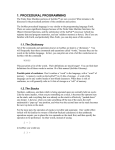
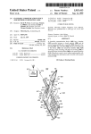
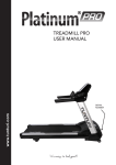
1
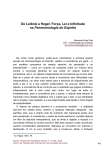
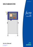
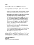
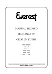
Aquatic Guidance Systems’ Autonomous Boat
Paul Hansen
Richard Wright
Tyson Ellsworth
Edward St. Louis
Nick Edwards
801-556-4509
435-406-1756
801-540-2539
801-718-1086
801-842-1502
[email protected]
[email protected]
[email protected]
[email protected]
[email protected]
www.aquaticguidancesystems.com
ABSTRACT
How can a fisherman troll from a motorboat without simultaneously piloting the boat?
Our Aquatic Guidance System, with both conventional and auto-pilot steering, allows
fishermen to concentrate on fishing. This guidance system integrates automated steering,
transmission, and throttle control with a graphical user interface (GUI). The GUI allows
the user to control the boat, input commands, and choose path specifications. Sensor data
is used to display readings for the boat’s current depth, compass, and GPS data (current
location and heading). A two-dimensional (2-D) lake map featuring boat position, trace
of the path taken, and the projected path is also displayed.
For steering, throttle, and mechanical requirements, our design utilizes components
designed by Kairos Autonomi, a manufacturer of systems that enable vehicles to become
autonomous. Our design includes a safety system that involves manual override,
shoreline avoidance, and emergency stopping. For the GUI, our design uses the objectoriented programming language C# which is suitable for systems in which the computer
is completely dedicated to the device it controls. Our platform is a 19.5 foot Bayliner
Classic motorboat. Beyond the sport of fishing, our Aquatic Guidance System can be
adapted for military, law enforcement, commercial, and other recreational uses.
TABLE OF CONTENTS
1 INTRODUCTION
2 GRAPHICAL USER INTERFACE
3 STEERING SYSTEM
4 SENSORS
5 MECHANICAL INTERFACE EQUIPMENT
6 SAFETY SYSTEM
7 CONCLUSION
REFERENCES
ACKNOWLEDGEMENTS
2
3
6
8
12
13
15
15
15
1. INTRODUCTION
Our design integrates a Pronto4 kit with a GUI, allowing the user to control the speed
and path of a 19.5 foot Bayliner Classic motorboat. The design involves collecting data
from several different sensors and analyzing that data to keep the boat on a specific path
with little or no variance. The challenge we faced was to use automated steering,
transmission, and throttle control to keep the boat on the path specified by the user.
Several functions are available to the user. One of the main things the user is able to do is
designate a suggested speed at which the boat should travel. Also, there are two different
options for the user to use in specifying a path:
2
1. The user is able to select different waypoints from a map of Strawberry Reservoir’s
Renegade Bay and the boat follows the path designated by the waypoints.
2. The user is able to specify a certain depth in which the boat should travel by
analyzing a 2-D contour map of Renegade Bay and choosing waypoints in the
specified depth. The boat follows that specific depth around the lake or between
waypoints, keeping the boat in water of the specified depth.
The GUI has several capabilities beyond those described above. Two of these capabilities
deserve notice:
1. The GUI displays a detailed contour map of the lake with the current location,
past route, and future route of the boat prominently featured upon the map.
2. The GUI displays sensor data to the user. The compass, current depth, and
current GPS location and heading are displayed.
The design includes a safety system. The safety system involves three main components:
1. There is a manual override for the boat. All the user has to do is flip the switch
below the steering wheel from the automatic setting to the manual setting.
This disables the autonomous elements of the boat and gives the user full
control of the steering, transmission, and throttle.
2. There is a remote shut-off capability where someone can press an emergency
stop button that throttles the engine down and puts the transmission into
neutral.
3. Another safety feature is shoreline avoidance. If the boat enters water that is
under a specified depth, the boat immediately throttles down and moves the
transmission into neutral.
By retrofitting the Pronto4 kit from Kairos Autonomi onto a 19.5 foot Bayliner Classic
motorboat and integrating our GUI, our design provides fishermen the ability to troll in
Renegade Bay without the hassle of piloting the boat. In addition to fishing, it is feasible
to adapt our system for other uses.
This document details the implementation of this design. Each major heading outlines a
particular aspect of the design: the graphical user interface, the steering system, the
sensors, the mechanical interface equipment, and the safety system.
2. GRAPHICAL USER INTERFACE
This section details the functionality of the graphical user interface. To understand much
of the GUI it is important to understand that the extensible markup language (XML) is
used to contain much of the data. XML is used because it is easy to read and C# has great
XML processing capabilities. The file format for a two line-segment path is shown
below:
3
<?xml version="1.0" encoding="utf-8"?>
<information>
<createdate>
<date>11/26/2007</date>
</createdate>
<savedate>
<date>11/26/2007</date>
</savedate>
<path>
<type>not defined</type>
<speed>0</speed>
<depth>0</depth>
<numpts>3</numpts>
<waypoint>
<x>397</x>
<y>281</y>
</waypoint>
<waypoint>
<x>456</x>
<y>270</y>
</waypoint>
<waypoint>
<x>428</x>
<y>251</y>
</waypoint>
</path>
</information>
Note: This file does not contain any information about the GPS locations of each
waypoint. It only keeps track of where the user clicked on the image when they
made the path. We use the same file format above to store GPS locations. Using
XML allows us to easily change the path in a text editor or with the GUI.
Since the menu options and main screen of the GUI provide a concise overview of the
functionality of the GUI, the rest of this section will list and explain the menu options of
the GUI.
The file menu:
Open - Open a path file.
Open GPS - Open a path file that contains only GPS data.
Close - Close the current path.
Save - Save the path using non-GPS data to a file.
Save As - Save the path using non-GPS data to a file. The user must type in the
filename.
Exit - Closes the GUI.
4
The GPS menu: The options of this menu handle all GPS functionality. We get the GPS
data from a fish-finder unit that communicates with the GUI using shared
variables.
Log Data - Each time the shared variables get updated we have the option
to record the GPS location in a file.
Start Logging - Starts sending GPS locations to a file.
Pause Logging - Stops sending GPS locations to a file until the user Starts
Logging again.
Stop Logging - Stops sending GPS locations to a file. The user is then
prompted to save the file.
Configure - Used to Configure the current GPS location to a pixel on the
image of the lake.
The debug menu:
Debug - To debug our control system we use a Graphical Debugger and
Simulator. A unique feature is on the fly debugging of a simulation.
Graphical Debugger - Shows where the boat and the meatball are located. (See
the section on the steering system for more information
about the meatball.)
Simulator - Simulates how the steering system will control the boat for a
certain path and control parameters.
The toolbar menu:
This menu gives the user options to graphically manipulate the boat's path.
Arrow - Used to select a single point or multiple points.
Add Point - Adds a point to the end of the boat's path.
Move - Moves selected point(s) to another location.
Delete - Remove selected point(s) from the path.
Bezier Curve Path - Create a path using a Bezier Curve.
Circle Path - Create a path using a circle.
The auto-snap function:
On/Off Checkbox - When on, determines if the mouse location is close
enough to a point on the screen and if so will move the
mouse location to that point.
The main screen of the GUI displays an image of Renegade Bay that aids the user in
making paths. This image displays the boat position, trace of the path taken, and the
projected path.
5
3. STEERING SYSTEM
This section details the steering control algorithm and the depth following capability of
the aquatic guidance system.
A. Feed-Forward Steering
The steering system uses feed-forward control techniques. The general idea is to calculate
a point in front of the boat towards which the boat always steers. This point has been
called a meatball. This is analogous to a carrot being placed in front of a donkey to allow
a rider to steer it left or right. Using this technique, the steering system can be separated
into two portions, one which calculates the position of the meatball, and another that
steers the boat towards this point.
The meatball position is calculated at a specified distance in front of the boat in the
direction of the line segment that is being followed. This variable distance can be set
either closer or farther away, with this variable distance determining system response. If
the meatball is too close, then any noise in the system will cause the boat to oscillate
significantly. Placing the meatball too far away reduces the response time of the system,
removing the ability to follow a detailed course.
The actual steering angle sent out to the steering wheel is determined by a look-up table
that was created by driving around in circles; the boat set the steering wheel to a certain
angle, waited for the boat to complete a full circle, and then calculated the curvature of
that circle. The desired curvature is calculated from the current position of the boat along
with the meatball and GPS heading. A simple linear interpolation method is used to
determine the output angle to the steering wheel. The desired curvature is calculated as
the curvature of the arc between the two points that is tangent to the current heading of
the boat at the boat's location as shown in Figure 1 below.
Figure 1. Example of curvature calculation.
6
B. Depth Following
The depth following implementation of our boat design began before the implementation
of any other part of the project. We use computer vision algorithms and techniques to
take a scanned topographical (contour) map image of Strawberry Reservoir and convert it
into a three-dimensional (3-D) computer model (adding depth as the 3rd dimension) [5].
The 3-D computer model is then used to generate a path at a specific depth around the
lake that can be loaded directly into the boat’s GUI.
As shown in Figure 2 below, we scan in a topographical image of Renegade (or Indian
Creek) Bay. This is a part of Strawberry Reservoir where we conducted most of our
testing. There are various markings and lines to show the approximate depth of the water
at any given point in bay.
Figure 2. Scanned topographical map image
Over-simplifying the many computer vision algorithms we used, we run this image
through MATLAB code that finds the lines that separate the different depths and “fillsin” the regions corresponding to specific depths [5]. The code then interpolates between
these regions to produce a 3-D computer model as shown in Figure 3. Using the model in
Figure 3, we are now able to find the approximate depth at any given point in Renegade
Bay. Using this model and additional algorithm techniques we are able to generate an
XML file containing a path that follows a given input depth. This XML path file can be
loaded directly into the boat’s GUI application and the boat can immediately begin
following the specified depth around the bay.
Figure 3. 3-D computer model of map image
7
4. SENSORS
This section describes shared variables and the various sensor interfaces.
A. Shared Variables
The sensor data is brought into the computer using two different serial streams that are
parsed by separate programs. Shared variables are used to communicate between these
programs and the GUI. The shared variables are part of a library created by Edelwise.
These beWISE shared variables are the standard used with the Pronto4 kit. The library
used was made to link with Visual Basic 5. In order to get access to these shared
variables in C# (.NET 2.0) a Dynamically Linked Library (DLL) wrapper was made in C.
This DLL is accessible from Visual Studio 2005 and in particular C#.
The interface for the shared variables is very simple. Shared variables can be created,
written to, and read from. They perform just like a global variable in a program,
inasmuch as they can be written to or read from any part of the program. The benefit of
using this DLL is that shared variables can be written to or read from any program that is
running on the computer. In order to control the flow of data, only one program is
allowed to write the data. Thus, the program that reads the GPS information periodically
updates the GPS location variables, and other programs read this data and do any
necessary calculations.
B. Sensor Interfaces
This section describes the compass, transmission, microcontroller, GPS, and sonar
interfaces.
Compass Interface Specification
The compass module has pin outs as shown below in figure 4.
Figure 4. The compass module
8
To power the compass sensor requires a 5V power supply at 15 mA. To get the compass
reading out of the chip we are using the I2C interface provided by pins 2 and 3. The data
that comes from pins 2 and 3 is a 2 byte integer. This integer represents the compass
bearing as 0-3599 corresponding to 0-359.9 degrees. To get the compass bearing from the
sensor requires completing the following steps:
1. Send a start sequence
2. Send 0xC0 (I2C address of the CMPS03 with the R/W bit low (even address))
3. Send 0x01 (Internal address of the bearing register)
4. Send a start sequence again (repeated start)
5. Send 0xC1 (I2C address of the CMPS03 with the R/W bit high (odd address))
6. Read data byte from CMPS03
7. Send the stop sequence.
The bit sequence looks like this:
Transmission Sensors
The laptop software and Pronto4 kit have control over the throttle and transmission. As
such, it is necessary for the software to know which direction the transmission is engaged
in: forward, reverse, or neutral. This keeps the software from revving the engine while
the transmission is in either reverse or neutral.
The way this is done is by attaching magnets next to the transmission push-pull cable.
Two reed-switch sensors are placed under the corresponding positions for forward and
reverse. One sensor conducts a signal when the transmission is in forward and the other
sensor conducts a signal when the transmission is in reverse. When the transmission is in
neutral, neither reed-switch senses the magnet; so neither one conducts a signal.
We use the microcontroller to detect a 5V signal coming in through each of the reedswitch sensors. The direction data is built with forward as bit 0, and reverse as bit 1. Thus
if direction = 01, the transmission is in forward. Direction = 10 means that the
transmission is in reverse. Direction = 00 means that the transmission is in neutral. If we
ever detect direction = 11, it means there is some sort of error and the sensors should be
inspected.
9
Microcontroller/Computer Interface
The microcontroller (Freescale MC9S12C32) has a built-in serial communications port
(DB9). This port is designed to load programs into the flash memory on the chip. The
pins of this port, however, are also accessible through the software running on the device.
As such, we send sensor data to the computer from the microcontroller via this serial
port.
We use the standard RS232 protocol to transfer data packets between devices. Two-way
communication is necessary since we are implementing a polling program on the laptop.
The laptop sends a request for the sensor data, and the microcontroller responds with all
of the latest data it has collected from the sensors. Because high bandwidth is not
necessary, we use a half-duplex SCI (asynchronous) communications scheme.
Using the RS232 protocol, we send a total of 11 bits for each byte of data transferred: one
start bit followed by the eight data bits, after which a parity and stop bit are transmitted.
The parity bit is optional in the protocol, but we like to be able to detect erroneous
transfers.
The laptop initiates data transfers from the microcontroller by sending either a ‘c’ or an
‘x’ character. If ‘c’ is received, all data is recorded and sent, including the current
compass reading. If ‘x’ is received, all data is still recorded and sent, but the old compass
reading is sent, thus eliminating I2C overhead when compass data is not needed. This
data is sent as a serial stream of 15 bytes. This stream is split into five 3-byte sections.
Each section consists of an identifying character byte, and two corresponding data bytes.
The identifying byte specifies which sensor’s data is to be sent in the following two
bytes. These sections are: tachometer, barometer, velocity, compass, and transmission.
The first three of these sections are actually not even used. The original idea was to pass
in engine RPM, and boat speed using voltage ADCs and pitot tubes (anemometers). It
was later learned passing the engine RPM is not necessary and that GPS readings give
adequate information regarding speed. The compass and transmission sensors were
described earlier. By using this protocol, we maintain the ability to expand from five
sensors up to 256 different sensors.
ASCII
Character
‘T’
HexValue
0x54
Binary-Value
Sensor
0101 0100
‘B’
‘V’
‘C’
‘D’
0x42
0x56
0x43
0x44
0100 0010
0101 0110
0100 0011
0100 0100
“Tachometer” from the motor’s
tachometer
“Barometer” from the anemometer
“Velocity” from the other anemometer
“Compass” from the digital compass
“Direction” transmission sensor
10
GPS and Sonar Interface
The sonar and GPS readings are gathered using a Humminbird 383c fish finder unit. Both
the GPS and the sonar data are transmitted from the fish finder unit using the National
Marine Electronics Association (NMEA) standard protocol [1] [2] [3] [4]. The NMEA
standard uses serial communications with the ASCII character set. The standard is
designed to have one device broadcast the data to multiple listening devices; therefore, no
verification of receipt is required.
The NMEA protocol adheres to the following rules. First of all, each new message begins
with the '$' character. The next five characters specify what type of message is being sent.
The data fields appear next; these fields are comma delimited and depend on the type of
message. An asterisk immediately follows the data fields. Following the asterisk is a twodigit checksum used to verify the transmitted data. The configuration for the serial port is
specified for a 4800 baud rate with 8 data bits, no parity, and one stop bit.
The NMEA standard allows for multiple receivers to be connected to one sending unit. In
this design a Humminbird 383c fish finder unit is used as the sender. This is connected to
a laptop through a serial communications port. A program is used to analyze the
incoming data and extract the current latitude, longitude, velocity, heading, and depth;
placing the needed data into shared variables that can be viewed by the control software
and GUI. The program analyzes five types of messages, shown in the below table.
NMEA Message Type
$INGLL
$INRMC
$INGGA
$INVTG
$INDPT
Extracted Data
Latitude and Longitude
Heading, Latitude, and Longitude
Latitude and Longitude
Velocity and Heading
Depth
It should be noted that the heading, latitude, and longitude are extracted out of several
different message types. Each message type occurs on regular intervals, but the data is
required by the control software on a more frequent basis than can be supplied by one
type of message, so multiple message types are analyzed. An important fact is that even
though the heading is extracted out of two different message types, the heading data is
not supplied often enough to the computer; therefore, since heading data does not arrive
as frequently as is required, the boat often weaves back and forth when trying to maintain
a straight course. This weaving motion is minimized by a change to the steering control
algorithm, namely, changing the distance the target point, commonly known as the
meatball, is from the boat. However, in order to eliminate the weaving problem a more
expensive GPS/sonar unit would have to be used.
11
5. MECHANICAL INTERFACE EQUIPMENT
The mechanical equipment of the boat is interfaced with the computer by using a unit
known as the Pronto4 kit. The Pronto4 kit was developed to give programmers access to
the physical control of any vehicle. In this design the Pronto4 kit is used to perform
several functions: power distribution to the various systems on the boat, control of the
steering wheel, and control of the throttle and transmission. These three functions of the
Pronto4 kit are described in this section.
The power is taken from the boat’s battery and routed to a power distribution unit
designed by Kairos Autonomi. This unit distributes power to the laptop, steering ring,
sensors, and servos. Connecting this unit to the battery makes it possible to drain the
battery if the boat’s engine is not turned on. To compensate for possible power drain from
the battery - the microcontroller, sensors, and other power draining systems can be
shutoff using a switch installed near the back of the boat.
To control the steering wheel a ring is mounted onto the steering wheel that allows the
steering wheel to be turned the number of degrees specified by the steering system.
Internally, the steering ring uses a chain that rotates around a gear. This gear is controlled
through the use of shared variables.
The Pronto4 kit also provides the ability to control the throttle and transmission. The
throttle and transmission are controlled by push-pull cables connected to the servopod,
which manipulates the push-pull cables. The servopod is controlled through the use of
shared variables and a program called Servopod designed by Kairos Autonomi. The
servopod is used in automatic mode, but while the boat is in manual mode the throttle and
transmission are controlled in the normal manner. To allow the boat to be controlled in
both manual and automatic modes, four sets of push-pull cables are used. Two push-pull
cables are used for the throttle (manual/automatic modes) and two for the transmission
(manual/automatic modes). The interfacing of the push-pull cable used to control the
transmission in manual mode is described in more detail in the sensor section.
The Pronto4 kit communicates with various pieces of software through the use of shared
variables. The Pronto4 kit is compatible with the Joint Architecture for Unmanned
Systems (JAUS) protocol. The JAUS protocol specifies a communication protocol that
makes it convenient to share messages between different computers and various sensor
devices. A program called djDrivenByWire converts the shared variables to a serial
stream that is outputted directly to the Pronto4 kit. The actual protocol that is used is
described in a private, unpublished document to which we have been given access [6].
12
6. SAFETY SYSTEM
This section details the design of the safety system. The three major portions of the safety
system are manual override, emergency stop, and shoreline avoidance.
A. Manual Override
When building an autonomous boat (or pretty much anything autonomous for that
matter), safety is a huge concern. The Pronto4 kit is installed in such a way that manually
overriding the system is very simple; flip a switch, and the boat is completely
controllable by the human driver. If the boat becomes unstable, takes a dangerous course,
or does anything undesirable, the automation can be overridden and safely corrected as
long as someone is in the boat to flip the manual override switch.
Our safety application extends the manual override capabilities of the Pronto4 system for
an even safer operation. There are two main functions of the safety application, remote
emergency stopping and shoreline avoidance.
B. Emergency Stop
We found it impractical to have an autonomous boat that requires a human to be on board
in order to safely operate. Taking advantage of the shared variables we currently use to
control the Pronto4 system, this design incorporates a remote emergency stop feature.
Shared variables are invaluable for communicating between distinct applications on the
same PC. Using a shared link (part of the shared variables package), we are able to
expand this communication across an entire network. The shared link application allows
us to specify which of the shared variables should be shared on the network, and which
shared variables should be updated from the network. The shared link application then
rapidly transfers and receives UDP packets to keep both ends of the link updated. Writing
to a shared variable on one PC automatically updates a shared variable on another PC.
We set up a wireless network to allow remote communication between two PCs.
Understanding that the wireless network could potentially fail at any time (especially if
the computers are at a great distance from each other), we designed a “fail-safe” remote
shut-off system. The remote PC (the laptop computer not physically connected to the
autonomous boat) runs a safety application that simply increments a shared variable a
few times each second. A large red button is displayed along with the word “STOP!” as
shown in figure 5. When this button is pressed, the shared variable stops being
incremented, and the red “STOP!” becomes a green “GO!” as shown in Figure 5.
13
Figure 5. Remote E-Stop Application
On the other end of the shared link there is the PC laptop controlling the Pronto4 system.
The safety application running on this PC continuously checks the incrementing shared
variable at 500 millisecond intervals. If it fails to see the variable incrementing, it
immediately throttles down the boat and puts it into neutral. The boat must then be
reinitialized both locally and remotely. The throttle and transmission shared variables
must be updated locally along with the re-initialization of the safety application (by
clicking “Turn ON remote shut-off capability.”), and the “GO!” button on the remote
stop application must be pressed to begin incrementing the counter shared variable again.
If the boat travels outside of the wireless network, or if the wireless network connection
is interrupted, the boat will only need to be reinitialized locally, as the shared variable
will still be incrementing on the remote PC and through the shared link.
C. Shoreline Avoidance
The safety application running on the PC laptop controlling the Pronto4 system not only
stops the boat when the emergency stop button is pressed or when the network
connection is lost, but also when the boat is about to run into the shore. We have no
sensors to accurately detect the shoreline, and the pre-generated depth and shoreline lake
models are not accurate enough to precisely avoid the shore in all cases, so we utilized
our sonar sensor to detect when the water depth is becoming too shallow for safe
operation.
As with the remote emergency stop feature, the safety application checks the water depth
every 500 milliseconds by reading a shared variable updated by the GPS/sonar reading
application. If the water depth drops below a threshold set by the user (see test box in
figure 6 below), the safety application will immediately throttle down the engine and put
the boat into neutral. This will allow the boat to avoid impacting the shore completely, or
at least allow the boat to safely drift ashore without the propeller spinning.
Figure 6 Safety Application
14
After an emergency stop has been initiated by the depth-checking part of the safety
application, the throttle and transmission shared variables must be reinitialized, along
with the safety application itself (by clicking “Turn ON shoreline avoidance”).
7. CONCLUSION
This design is a great success and it is a joy to ride in Aquatic Guidance Systems’
autonomous boat. By retrofitting the Pronto4 kit from Kairos Autonomi onto a 19.5 foot
Bayliner Classic motorboat and integrating our GUI, this design provides fishermen the
option to troll for fish in Renegade Bay without the worry of piloting the boat. Our
Aquatic Guidance System provides both conventional and auto-pilot steering with the
safety of manual override, remote shut-off, and shore line avoidance. It is feasible to
adapt this system for military, law enforcement, commercial, and other recreational uses.
REFERENCES
[1]Humminbird 383c User Manual
[2]http://www.interfacebus.com/NMEA-2000_Standard.html , 2007.
[3]http://www.werple.net.au/~gnb/gps/nmea.html, 2007.
[4]http://www.gpsinformation.org/dale/nmea.htm, 2007.
[5]Forsyth, David A. and Ponce, Jean Computer Vision A Modern Approach. Pearson
Education, Inc., Upper Saddle River, New Jersey. 2003.
[6] Unpublished technical document explaining interface protocol for the Pronto4 kit
ACKNOWLEDGEMENTS
The design detailed in this paper would not have been possible with out significant
support from Kairos Autonomi, Ken Stevens, and our families.
15