1
2
Cyber–Champ ™ Amplifier
Important Safety Instructions
• This symbol warns the user of dangerous
voltage levels localized within the enclosure of
the unit.
• This symbol advises the user to read all
accompanying literature for safe operation of
the unit.
• Read, retain, and follow all instructions.
warnings.
Heed all
• Only connect the electric line cord to an earth grounded
AC receptacle in accordance with the voltage and
frequency ratings listed under INPUT POWER on the
rear panel of this product.
• WARNING: To prevent damage, fire or shock hazard,
do not expose this unit to rain or moisture.
• Unplug the AC power line cord before cleaning the unit
exterior (use a damp cloth only). Wait until the unit is
completely dry before reconnecting it to power.
• Maintain at least 6 inches of unobstructed air space
behind the unit to allow for proper ventilation and cooling
of the unit.
• This product should be located away from heat sources
such as radiators, heat registers, or other products that
produce heat.
• This product may be equipped with a polarized plug (one
blade wider than the other). This is a safety feature. If
you are unable to insert the plug into the outlet, contact
an electrician to replace your obsolete outlet. Do not
defeat the safety purpose of this plug.
• Protect the power cord from being pinched or abraded.
• This product should be serviced by qualified service
personnel when: the power supply cord or the plug has
been damaged; or objects have fallen, or liquid has been
spilled onto the product; or the product has been
exposed to rain; or the product does not appear to
operate normally or exhibits a marked change in
performance; or the product has been dropped, or the
enclosure damaged.
• Only use a cart or stand with this product that is
recommended by this product’s manufacturer.
• The power supply cord of this product should be
unplugged from the outlet when left unused for a long
period of time, or during electrical storms.
• Do not drip nor splash liquids, nor place liquid filled
containers on the unit.
• CAUTION: No user serviceable parts inside, refer
servicing to qualified personnel only.
• Fender® amplifiers and loudspeaker systems are capable
of producing very high sound pressure levels which may
cause temporary or permanent hearing damage. Use
care when setting and adjusting volume levels during
use.
FCC COMPLIANCE NOTICE
This equipment has been tested and found to comply
within the limits for a Class B digital device, pursuant to
Part 15 of the FCC rules. These limits are designed to
provide a reasonable protection against harmful
interference in a residential installation. This equipment
generates, uses and can radiate radio frequency
energy and if not used in accordance with the
instructions, may cause harmful interference to radio
communications and there is no guarantee that
interference will not occur in a particular installation. If
this equipment does cause harmful interference to
radio or television reception, which can be determined
by turning the equipment off and on, the user is
encouraged to try to correct the interference by one or
more of the following measures: reorient or relocate the
receiving antenna, increase the separation between the
equipment and receiver, connect the equipment into an
outlet on a circuit different from that of the receiver.
Consult the dealer or an experienced radio/TV
technician if help is needed.
A PRODUCT OF:
FENDER MUSICAL INSTRUMENTS CORPORATION
CORONA, CA USA
Copyright ©2003 by FMIC
Trademarks
Blackface™, Cyber–Champ™, Champ®, Cyber–Twin™, Cyber-Series™,
Deluxe™, Dyna–Touch™, Mr. Gearhead™, Virtual Tone Interpolation™,
Bassman®, Deluxe Reverb®, Fender®, Princeton®, Twin Reverb®,
and all related logos, are trademarks or registered trademarks of FMIC.
Other trademarks are properties of their respective owners.
w w w.f e n d e r.com
✧
w w w. m r g e a r h e a d .net
Cyber–Champ ™ Amplifier
3
I n t ro d u c t i o n
Your new Cyber–Champ™ amplifier is brought to
you by the same Tone–team that created the
Fender® Cyber–Twin™ and Cyber-Deluxe™
amplifiers.
As the crowning achievements of
Fender’s most advanced research and development
project, Cyber–Series™ amplifiers are endowed
with Fender’s exclusive Virtual Tone Interpolation™
technology (patent number 6,222,110).
VTI™
technology enables the Cyber–Champ™ amplifier
to be different amplifiers according to circuit design.
Starting with a virtual circuit board, the
Cyber–Champ™ amplifier "rewires" its fundamental
architecture to become the essence of some of the
amplifier greats — Fender’s Blackface™,
Dyna–Touch™, Tweed and Modern amps, and even
the best of the British amps!
The Cyber–Champ™ amplifier allows you to be the
amp designer. Start with one of 14 permanent amp
and effect setups stored within the Cyber-Champ™
amp—twist some knobs, make some changes, then
save to one of the 7 rewritable preset locations
reserved onboard for your original amplifier designs.
MIDI implementation on the Cyber–Champ™
amplifier enables you to transfer presets to and from
the amp for backup to a PC, or for exchange with
other Cyber–Champ™ amplifier players.
The Cyber–Champ™ amplifier also puts a huge
array of studio–quality effects at your command:
Reverb, Modulation and Delay effects, enough to
satisfy most any sonic appetite. And many are in
stereo, so you can use the headphones jack to
enjoy a fully ambient stereo dimension.
The
Cyber–Champ™ amplifier’s Dyna–Touch™ power
amp circuitry and Celestion® speaker deliver
powerful, responsive Tone to you and your
audience. It’s not just loud “on paper.”
Feature s
• 21 Amp Design presets selectable using the Preset and Bank buttons or a MIDI controller:
• 14 Permanent presets – great amp and effects setups that are always available
• Fender® Custom Shop bank – 7 premium amp and effects combinations
• Your Amp Collection bank – 7 “stock” classic amplifiers
• 7 Rewritable presets – create and save your own amp and effects setups in the Players’ Lounge bank
• 3 groups of studio–quality effects that can be used simultaneously:
• 4 Reverb types with selectable levels and MIDI–accessible parameters
• 5 Modulation effect types with selectable levels and MIDI–accessible parameters
• 3 Delay effect types with selectable levels and MIDI–accessible parameters
• MIDI implementation:
• 27 Continuous Controllers for adjusting amp settings using external MIDI equipment (sequencer, computer,
foot–controller or Cyber–Series™ amplifier)
• Preset–defined Continuous Controller enables foot–pedal control of programmable parameters
• System Exclusive functionality for selective preset management
• Front panel MIDI IN and MIDI OUT ports
• Virtual Tone Interpolation™ technology offers 7 Amp Type selections with tone stacks located before or
after the drive circuitry as appropriate
• Hum Reduction algorithm (patent pending) actively seeks out and suppresses environmental “hum”
• On–board digital chromatic tuner
• 65 watts of output power
• 12˝, 8Ω Celestion® speaker
• Stereo headphone/line out jack
Thank you for choosing Fender®
— To n e , Tr a d i t i o n a n d I n n o v a t i o n — s i n c e 1 9 4 6
w w w.f e n d e r.com
✧
w w w. m r g e a r h e a d .net
Overview
4
1 ✧ Over view
CUSTOM SHOP
AMP COLLECTION
PLAYERS’ LOUNGE
S
G
E
ANG
EN A
AR
PHONES
L
A
+40
MIDI
T APE
MO
IT
+10
T RE
DI G
G
IN TUNE
RU
IN
-10
E
CH O
SPR
-40
N
TO
KIN
L
UC
HA
LO
INPUT
OM
L
RO
MASTER
FL
BASS
MIDDLE
RA
TREBLE
VOLUME
VIB
GAIN
D
PHASER
REVERB
MOD. F/ X
IN
DEL AY
OUT
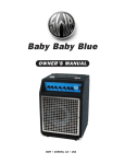
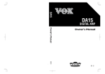
Operation Essentials
Each preset contains a complete set
of amplifier and effects settings.
There are three banks of presets:
CUSTOM SHOP
AMP COLLECTION
PLAYERS’ LOUNGE
Permanent
Permanent
Rewritable
Presets and Banks
The Cyber–Champ™ is instantly reconfigured each time you select a
preset. Use the preset buttons
to
select a preset in the current bank. Press the BANK button
, then
a preset button to select a preset from another bank. Note that when
you select a preset, the position of each knob will not reflect its actual
setting (except by coincidence) until it is captured . . .
Knob Capture
Capture control of a knob by turning it
until the adjacent LED lights up.
Capture happens when the knob
setting matches its actual (internal)
setting stored within the current
preset.
You can save 7 of your own amplifier
and effects settings in the Players’
Lounge bank of presets.
You must first “capture” control of a knob to adjust the setting.
Capture by turning the knob until the adjacent LED lights up. Once
captured, further adjustments are immediate and audible.
Saving Presets
Captured knob settings are released when you make a preset
selection . . . but you can save all your current settings simply by
holding any preset button in for 2 seconds. Your new preset is saved
into the Players’ Lounge bank, assigned to the button held. Your new
preset is automatically activated.
+ –
+ –
–
+
A. INPUT JACK
+ + –
–
–
+
+ + –
+
–
–
–
+
+
–
Input connection for+ your guitar. – The input level automatically
adjusts
itself to
+
–
+ circuitry.
–
–
+signal level is supplied –to the DSP
ensure an adequate
+
–
–
+
INPUT
B. GAIN
GAIN
VOLUME
-40
Controls the distortion level and contributes to the overall amp loudness. Use
VOLUME {C} to adjust for (normalize) any undesired volume level change
resulting from a GAIN level change.
-10
C. VOLUME
Controls the post–distortion signal level and contributes to the overall amp
loudness. Use in conjunction with GAIN {B} to normalize volume differences
between presets.
w w w.f e n d e r.com
✧
w w w. m r g e a r h e a d .net
+
+
–
–
+
–
Overview
5
D. TREBLE
TREBLE
BASS
MIDDLE
Controls the high–frequency tone level.
E. MIDDLE
+10
IN TUNE
+40
The tone controls come before or
after the distortion circuitry,
depending on the Amp Type of
the preset (see Presets starting
on page 7).
Controls the mid–frequency tone level.
F. BASS
Controls the low–frequency tone level.
G. MASTER
+ –
OM
Controls the overall volume output from the amplifier together with GAIN {B},
and VOLUME {D}. MASTER is the final “volume gatekeeper” limiting the
maximum output level of the Cyber–Champ™ amplifier. The MASTER knob
position (setting) is an absolute limit—even when controlling MASTER with MIDI
messages. MASTER is not preset programmable.
H. REVERB
HA
L
L
RO
MASTER
–
+
+
G
Reverb Type
SPRING
–
ROOM
HALL
ARENA
AR
IN
E NA
SPR
–
+ –
+
– increases
Selects a Reverb type and level. The level
going clockwise within
+
–
– as illustrated
+ from off (–), to maximum
each type
(+).
+
–
–
+
REVERB
Description
Bright Blackface™ Reverb with long decay
+
–
Bright room with medium decay
Medium-bright hall with long decay
Dark frequency response with long decay
+
I. MOD F/X
+ –
E
T RE
ON
AT
VIB
+
+ –
S
E
ANG
FL
RU
+
+
–
CHO
–
MO
LO
–
+
R
+ –
+
–
PHASER
+
MOD. F/X
–
–
+
Selects a Modulation effect type and level. The level increases going clockwise
– type +as illustrated from off (–), to maximum (+). Set a custom
within each
+
modulation rate by –pressing TAP at least twice at the desired rate. Press TAP
once for+the slowest rate possible. There is only one level setting for Phaser.
–
+
–
Modulation Effect Type
Description
+
–
+
–
–
+
CHORUS
Medium sweep rate with high depth
+ VIBRATONE –
Fast rate with medium depth
Fast rate with medium-high
+ – depth and duty cycle
Slow sweep rate–with medium+depth
Medium sweep
– rate with medium
+ depth
TREMOLO
–
–
+
+FLANGE
–
–
+
+
PHASER +
+
–
+
–
+
–
–
J. DELAY
+
+
–
DIGIT A
–
T APE
L
DU
+
–
CKIN G
+ –
+
+
–
DELAY
+
–
–
–
+
+
Selects a Delay type and level. The level increases going clockwise within each
type as illustrated from off (–), to maximum (+). Set a custom delay interval by
pressing TAP at least twice at the desired rate. Press TAP once for the longest
interval possible.
Delay Type
DIGITAL
TAPE
DUCKING
Description
130 ms delay, single repeat (panning)
300 ms delay, low feedback, medium wow & flutter
460 ms delay, medium feedback, “ducks” out of the way when playing
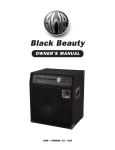
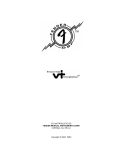
K. TUNER
Turns the tuner on and off. The tuner “borrows” the preset button lights to
indicate the nearest note and the capture LEDs to indicate flat, in tune, or sharp.
Half notes are indicated by two
preset button lights.
For
example, A and B would light up
to indicate A sharp (B flat).
Nearest Note ➜
Fine Tuning ➜
w w w.f e n d e r.com
✧
-40
-10
IN TUNE
+10
+40
w w w. m r g e a r h e a d .net
CUSTOM SHOP
AMP COLLECTION
PLAYERS’ LOUNGE
+
–
+
–+
+
AMP COLLECTION
–
+
+
––
PLAYERS’ LOUNGE
+
+
–
+ –
Presets and Banks
are described
in depth
– in Presets +starting on
page +7.
–
G
E
KIN
EN A
AR
+
–
+
–
–
– PRESET and+BANK BUTTONS
+ L.
–
–
–
CUSTOM SHOP
+ –
MOD. F/ X
D
IN
DEL AY
+ –
+
+
L
A
–
+
PHONES
PHASER
+ –
–
MIDI
T APE
MO
IT
S
+40
REVERB
+ –
T RE
DI G
+10
IN TUNE
RU
G
-10
E
CH O
IN
-40
N
TO
UC
L
ANG
HA
LO
INPUT
OM
L
RO
MASTER
FL
BASS
MIDDLE
RA
TREBLE
VOLUME
VIB
GAIN
SPR
–
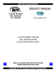
Overview
6
+
–
OUT
+
–
The A–G buttons –select presets
from the current –bank as +indicated by the color
+
coded bank LEDs. To activate a preset from a different bank, press the BANK
+ one or more times, then press a preset button.
button
Holding a preset button in for 2 seconds will save the current amplifier settings
to the Players’ Lounge bank under the button held. Your new preset is
automatically activated.
+ –
RESET: To reset the Players’ Lounge
bank
+ to factory presets, hold down the
–
+
–
+ buttons while turning
A– and G preset
the Cyber-Champ™
amplifier on.
+
–
M. HUM REDUCTION
–
+
–
–
+
Turns
Hum Reduction on and off.
Reduces
environmental hum in some
situations using an algorithm that seeks out hum frequencies and squelches
only the “hum” without degrading your music!
+
N. MIDI IN/OUT
MIDI
IN
OUT
Musical Instrument Digital Interface ports for connecting MIDI devices to the
Cyber–Champ™ amplifier. MIDI can be used to change and manage presets,
adjust settings, activate tuner mode and edit effect parameters. See MIDI
starting on page 9.
O. PHONES
PHONES
Connect your stereo headphones here. This output jack can also be used as a
stereo line out for connection to sound reinforcement or recording equipment.
P. RED JEWEL
It’s a
!
Rear Panel
Q. POWER
Turns the Cyber–Champ™ on and off.
R. IEC CONNECTOR
INPUT POWER
V
180W
Hz
Connect the included power cord in compliance with the voltage and
frequency ratings on the rear panel of your amplifier.
w w w.f e n d e r.com
✧
w w w. m r g e a r h e a d .net
Presets
7
2 ✧ Pr esets
This section defines the presets in each bank then describes how to customize
presets and effects.
CUSTOM SHOP
AMP COLLECTION
PLAYERS’ LOUNGE
Custom Shop Bank
The Custom Shop (permanent) presets contain premium amplifier and effect
combinations. Press BANK repeatedly until the red LED lights up, then press a
preset button (A–G) to activate a Custom Shop preset.
Preset
Name
Amp Type
Reverb
Modulation
Delay
A
Red
House
High-Gain Tweed with ‘59 Bassman®
Pre-Distortion tone controls
None
None
300ms Tape Delay, low feedback
with medium wow & flutter
B
R.I.P.
Max-Gain, Modern Heavy Metal Combo
with Post-Distortion tone controls
Room, dark frequency
response with short decay
Chorus, slow sweep
rate with high depth
None
C
Hang 10
Clean Tweed with ‘59 Bassman®
Pre-Distortion tone controls
Spring, bright Reverb with
long decay
None
130ms Tape Delay, low feedback
with medium wow & flutter
D
Texas
Shuffle
High-Gain Blackface™, with vintage PreDistortion Fender® Blackface™ tone controls
Spring, medium-bright
Blackface™ Reverb
Vibratone, fast rate
with medium depth
130ms Tape Delay, low feedback
with medium wow & flutter
E
Modified
Combo
Maximum-Gain Modern Modified Combo
with Post-Distortion tone controls
None
None
None
F
Euro
Trem
High-Gain British Combo with PostDistortion tone controls
None
Tremolo, fast rate
with high depth
None
G
Boris
Chorus
Clean Dyna–Touch™ with
Pre-Distortion tone controls
None
Chorus, slow sweep
rate with high depth
None
CUSTOM SHOP
AMP COLLECTION
PLAYERS’ LOUNGE
Preset
Amp Collection Bank
The Amp Collection (permanent) presets contain classic “stock” amplifiers.
Press BANK repeatedly until the yellow LED lights up, then press a preset
button (A–G) to activate an Amp Collection preset.
Name
Amp Type
Reverb
Modulation
Delay
A
‘49 Champ®
Crunch Tweed with ‘59 Bassman®
Pre-Distortion tone controls
None
None
None
B
‘55 Deluxe™
High-Gain Tweed, with ‘59 Bassman®
Pre-Distortion tone controls
None
None
None
C
‘65 Princeton®
Reverb
Clean Blackface™, with vintage PreDistortion Fender® Blackface™ tone controls
Spring, medium-bright
Blackface™ Reverb
None
None
D
‘65 Deluxe
Reverb®
Crunch Blackface™, with vintage PreDistortion Fender® Blackface™ tone controls
Spring, medium-bright
Blackface™ Reverb
None
None
E
Princeton®
65 DSP
High-Gain Dyna–Touch™ with PostDistortion tone controls
Hall, bright with
medium decay
None
260ms Digital Delay,
medium feedback
F
British
Invasion
Crunch Jangly British Combo with PreDistortion tone controls
Hall, bright with
long decay
None
None
G
Vintage British
Crunch
Crunch vintage British Combo with
Post-Distortion tone controls
None
None
None
w w w.f e n d e r.com
✧
w w w. m r g e a r h e a d .net
Presets
8
CUSTOM SHOP
AMP COLLECTION
PLAYERS’ LOUNGE
Players’ Lounge Bank
The Players’ Lounge (rewritable) presets are outfitted from the factory with a
variety of amplifier and effects combinations but they are rewritable for your
own preset designs. Press the BANK repeatedly until the green LED lights up,
then press a preset button (A–G) to activate a Players’ Lounge preset.
NOTE: The table (below) will not be valid for presets that you have customized.
Resetting will erase any custom
presets you have created.
Preset
RESET: To reset the Players’ Lounge bank to factory presets, hold down the
A and G preset buttons while turning the Cyber–Champ™ amplifier on.
Name
Amp Type
Reverb
Modulation
Delay
A
Stadium
Rock
Higher-Gain British Combo with PostDistortion tone tone controls
Arena, bright frequency
response with long decay
None
300ms Tape Delay, low feedback
with medium wow & flutter
B
Morning
Light
Clean Blackface™, with vintage PreRoom, bright frequency
Distortion Fender® Blackface™ tone controls response with medium decay
Vibratone, fast rate
with medium depth
None
C
Psychobilly
High-Gain Tweed with ‘59 Bassman®
Pre-Distortion tone controls
Room, dark frequency
response with medium decay
None
130ms Tape Delay, low feedback
with medium wow & flutter
D
Nü-D
Maximum-Gain, Modern Heavy Metal
Combo with Post-Distortion tone controls
Room, dark frequency
response with medium decay
Chorus, slow sweep
rate with high depth
100ms Tape Delay, low feedback
with medium wow & flutter
E
Clean
Arena
Crunch Blackface™, with vintage PreArena, bright frequency
Distortion Fender® Blackface™ tone controls response with long decay
None
None
F
Jazz
Box
Clean Dyna–Touch™ with
Pre-Distortion tone controls
Hall, bright frequency
response with medium decay
None
None
G
Barracuda
Maximum-Gain, Dyna–Touch™
Pre-Distortion tone controls
Room, dark frequency
response with medium decay
Phaser, medium sweep
rate with medium depth
350 ms Ducking Delay,
medium feedback, high ducking
Preset Editing
You can use a Players’ Lounge preset
as the starting point for a new preset,
but the descriptions in the table above
will no longer be valid for presets you
have customized.
You can create 7 of your own presets and save them in the Players’ Lounge
bank. First select any preset with the desired Amp Type as the foundation for
your new preset — see the tables on pages 7 and 8. Then adjust the amplifier
settings any way you like. When satisfied, press and hold any preset button
for 2 seconds. Your new preset is saved in the Players’ Lounge bank
(assigned to the button held) and it is automatically activated.
NOTE: The previous contents of the Players’ Lounge preset you are saving to
will be overwritten with your new preset.
Effect Editing—Advanced
A computer with a MIDI capable
soundcard, appropriate adapters and
a MIDI utility application are required for
advanced effect editing.
Using a computer you can edit effect parameters that are inaccessible through
the Cyber–Champ™ front panel controls. Your modified effect can then be
saved to a Players’ Lounge preset and used in the modified form using the front
panel controls (See Advanced Effect Editing on page 10).
w w w.f e n d e r.com
✧
w w w. m r g e a r h e a d .net
+ –
+ –
+
–
+
–
–
–
+
+
–
3 ✧ MIDI
MIDI
IN
+
–
+
+
+
–
–
MIDI
9
+
–
This section describes the Musical Instrument Digital Interface (MIDI)
capabilities of the Cyber-Champ™ amplifier. The Cyber–Champ™ amplifier
supports the MIDI standard using the MIDI IN and OUT jacks on the front panel,
both 5-pin DIN jacks. The amplifier uses Channel Messages and System
Exclusive Messages to accomplish the following tasks:
OUT
Channel Messages
See the MIDI Implementation Chart on
page 14 for details.
Switching Tuner and Effects On/Off
You can switch the tuner on and off using MIDI program change 127 in any
bank (00, 01, 02). You can switch the effects (Modulation and Delay) on and off
using continuous controller 85—any value between 64 and 127 turns effects on
and any value between 0 and 63 turns effects off. Reverb is not affected.
See the MIDI Implementation Chart on
page 14 for details.
Echoing Control Changes
You can control two or more Cyber–Champ™ amplifiers as one by linking their
MIDI ports together. Connect MIDI OUT on the primary amplifier to MIDI IN on
the auxiliary amplifier and so on down the line. The first time each knob is used
you must capture it on all amplifiers before you can adjust the setting on all
amplifiers. To ensure that you have captured a particular setting on all
amplifiers, turn the knob through its full range of values, then to the desired
value. Further adjustments will be synchronized.
See the MIDI Implementation Chart on
page 14 for details.
Selecting Presets
You can select presets using MIDI program changes. A continuous controller
pedal set to number 11 can be used to control either the Modulation effect rate
or the Delay effect interval according to the program change number used:
MODULATION EFFECT RATE CONTROL
To switch your continuous controller
pedal between Modulation rate and
Delay interval for the same preset,
go up or down 30, respectively. For
example, 15 and 45 are both
preset F in the Amp Collection bank
but 15 controls Modulation rate and
45 controls Delay interval.
All program changes are made in MIDI
bank 00 and are echoed on transmit
channel 1.
Program
Change # Bank
0
1
2
3
Custom Shop
4
5
6
10
11
12
13
14
15
16
20
21
22
23
24
25
26
Preset
A
B
C
D
E
F
G
DELAY EFFECT INTERVAL CONTROL
Program
Change # Bank
30
31
32
34
Custom Shop
35
33
36
Amp Collection
A
B
C
D
E
F
G
40
41
42
43
44
45
46
Players’ Lounge
A
B
C
D
E
F
G
50
51
52
53
54
55
56
w w w.f e n d e r.com
✧
Preset
A
B
C
E
F
D
G
Amp Collection
A
B
C
D
E
F
G
Players’ Lounge
A
B
C
D
E
F
G
w w w. m r g e a r h e a d .net
10
MIDI
See the MIDI Implementation Chart on
page 14 for details.
Adjusting Amp Settings
You can adjust any knob on the Cyber–Champ™ amplifier using the following
continuous controller numbers. Values range from 0=off to 127=maximum.
Control changes can be recorded using
a sequencer so that you can play them
back during performances.
A sequencer must first capture knobs
before it can control their settings. To
do this, ramp the continuous controller
through the full range of values, then
return it to the desired value (setting).
The sequencer will then have active
control of the knob (parameter).
NOTE: If sequencer capture is lost (by
manually turning the knob for example)
the sequencer must recapture control
of that parameter to use it again.
See the MIDI Implementation Chart on
page 14 for details.
Continuous
Controller #
07
85
102
103
104
105
106
107
108
109
110
111
112
113
114
115
116
117
118
119
120
121
122
123
124
125
126
127
Parameter
Setting
Master Volume
Effects Off/On
Gain
Volume
Treble
Middle
Bass
Reserved
Master Volume
Reverb Level
Reverb Time
Reverb Dwell (Input)
Reverb Diffusion
Reverb Tone
Modulation Effect Level
Modulation Effect Rate
Modulation Effect Parameter 2
Modulation Effect Parameter 3
Modulation Effect Parameter 4
Tap Interval
Delay Level
Delay Time
Delay Feedback
Delay Parameter 2
Delay Parameter 3
Reverb, Multi-Effects
Modulation Effect, Multi-Effects
Delay, Multi-Effects
(0-63=off, 64-127=on)
(see page 11)
(see page 11)
(see page 11)
(see page 12)
(see page 12)
(see page 12)
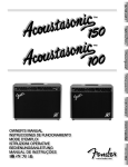
Advanced Effect Editing
Reverb
Reverb parameters in the figure and table below are accessible only by MIDI
continuous controller numbers 109-113 and have a value range of 0-127.
G
AR
IN
ENA
RO
L
REVERB
SPR
Reverb parameter
Continuous Controller
numbers
HA
OM
L
All 4 Reverb types have the same
5 editable parameters.
CC#
109
110
111
112
113
Reverb (all)
Level
Time
Dwell
Diffusion
Tone
SPRING, ROOM, HALL, ARENA — Parameter value definitions
Level
Time
Dwell
Diffusion
Tone
Amount of Reverb (0 is off, 127 is maximum)
Duration of Reverb sustain (0 is shortest, 127 is longest)
Signal level input to the Reverb circuit (versus output level controlled by the REVERB knob). (0 is minimum, 127 is maximum)
Density of Reverb from sparse with non–uniform decay, to dense with smooth decay (0 is sparsest, 127 is smoothest)
Brightness of Reverb (0 is darkest, 127 is brightest)
w w w.f e n d e r.com
✧
w w w. m r g e a r h e a d .net
MIDI
11
Modulation Effects
Modulation Effect parameters in the figure and table below are accessible for
the current effect type only by MIDI continuous controller numbers 114-118
(except Rate (CC# 115) which is also accessible by the TAP button).
Continuous controller messages have a value range of 0-127.
Vibratone
Level
Rotor Speed
Doppler Freq. Shift
Low-Pass Filter Range
Left/Right Phase
T RE
Phaser
Level
Rate
Depth
Feedback
Stereo Spread
MO
GE
VIB
E
Flange
Level
Rate
Depth
Feedback
Left/Right Phase
LO
RU
AN
CHO
Modulation effect parameter
Continuous Controller
numbers
N
TO
Tremolo
Level
Rate
Depth
Offset
Shape
S
FL
Chorus
Level
Rate
Depth
Avg. Delay Time
Left/Right Phase
RA
CC#
114
115
116
117
118
PHASER
CHORUS — Parameter value definitions
Level
Rate
Depth
Average Delay Time
Left/Right Phase1
Amount of the Chorus effect (0 is off, 127 is maximum)
Sweep rate of the Chorus effect (0.08 Hz selected as 0 is slowest, 10 Hz selected as 127 is fastest)
Amount of Doppler frequency shift and how apparent the Chorus effect sounds (0 is minimum, 127 is maximum)
Average delay time of the moving Chorus taps (repeats), use higher settings for doubling effect (0 is shortest, 127 is longest)
Stereo - Phase between left and right channel low frequency oscillators (0 is minimum stereo effect, 127 is maximum stereo effect)
VIBRATONE — Parameter value definitions
Level
Rotor Speed
Doppler Frequency Shift
Low-Pass Filter Range
Amplitude Modulation Depth
Amount of the Vibratone effect (0 is off, 127 is maximum)
Rate of the virtual rotating speaker baffle (0.08 Hz selected as 0 is slowest, 10 Hz selected as 127 is fastest)
Amount of Doppler frequency shift and how apparent the Vibratone effect sounds (0 is minimum shift, 127 is maximum shift)
Amount of high frequencies in the Vibratone signal (0 is minimum, 127 is maximum)
Amount the volume level varies with each cycle of the Vibratone effect (0 is minimum, 127 is maximum)
TREMOLO — Parameter value definitions
Level
Rate
Depth
Offset
Shape
Amount of the Tremolo effect (0 is off, 127 is maximum)
Cycle rate of the Tremolo effect (0.08 Hz selected as 0 is slowest, 10 Hz selected as 127 is fastest)
Amount the volume level drops with each cycle of the Tremolo effect (0 is minimum depth, 127 is maximum depth)
Offset of the low-frequency oscillator (0 is minimum, 127 is maximum)
Smoothness of the Tremolo waveform (0 is subtle and natural, 127 is choppy and percussive)
FLANGE — Parameter value definitions
Level
Rate
Depth
Feedback
Left/Right Phase 1
Amount of the Flange effect (0 is off, 127 is maximum)
Sweep rate of the Flange effect (0.08 Hz selected as 0 is slowest, 10 Hz selected as 127 is fastest)
Amount of Doppler frequency shift and how apparent the Flange effect sounds (0 is minimum effect, 127 is maximum effect)
Amount of the Flange signal that is fed back into the Flange circuit (0 is minimum feedback, 127 is maximum feedback)
Stereo - Phase between left and right channel low frequency oscillators (0 is minimum stereo effect, 127 is maximum stereo effect)
PHASER — Parameter value definitions
Level
Rate
Depth
Feedback
Stereo Spread 1
1
Amount of the Phaser effect (0 is off, 127 is maximum)
Sweep rate of the Phaser effect (0.08 Hz selected as 0 is slowest, 10 Hz selected as 127 is fastest)
Width of the Phaser sweep and how apparent the Phaser effect sounds (0 is minimum, 127 is maximum)
Amount of Phaser effect processed signal that is fed back (recycled) to the input (0 is minimum feedback, 127 is maximum feedback)
Stereo - Amount of stereo separation between left and right channels (0 is minimum stereo effect, 127 is maximum stereo effect)
This parameter modifies the stereo capabilities of your Cyber–Champ™ amplifier which can be enjoyed using the PHONES output jack.
w w w.f e n d e r.com
✧
w w w. m r g e a r h e a d .net
12
MIDI
Delay Effects
Delay Effect parameters in the figure and tables below are accessible for the
current effect only by MIDI continuous controller numbers 120-124 (except
Delay Time (CC# 121) which is also accessible by the TAP button). Continuous
controller messages have a value range of 0-127.
CC#
120
121
122
123
124
Digital
Level
Delay Time
Feedback
Low-Pass Freq. Cutoff
Input Level
Tape
Level
Delay Time
Feedback
Wow & Flutter
Low-Pass Freq. Cutoff
Ducking
Level
Delay Time
Feedback
Release Time
Ducking Threshold
T APE
L
D
TA
UC
DIGI
KING
Delay parameter
Continuous Controller
numbers
DIGITAL — Parameter value definitions
Level
Delay Time
Feedback
Low-Pass Frequency Cutoff
Input Level
Amount of the Delay effect (0 is off, 127 is maximum)
Interval between Delay repeats (30 milliseconds selected as 0 is shortest, 1450 milliseconds selected as 127 is longest)
Number of Delay repeats (0 is 1 repeat, 127 is many repeats)
Brightness of the Delay signal (0 is minimum (dark tone), 127 is maximum brightness)
Signal level going into the Delay effect (versus output level controlled by the numbered DELAY knob) (0 is minimum, 127 is maximum)
TAPE — Parameter value definitions
Level
Delay Time
Feedback
Wow & Flutter
Low-Pass Frequency Cutoff
Amount of the Delay effect (0 is off, 127 is maximum)
Interval between Delay repeats (30 milliseconds selected as 0 is shortest, 1450 milliseconds selected as 127 is longest)
Number of Delay repeats (0 is 1 repeat, 127 is many repeats)
Amount of random volume and pitch changes – tape recorder nostalgia effect (0 is minimum fluctuation, 127 is maximum fluctuation)
Brightness of the Delay signal (0 is darkest, 127 is brightest)
DUCKING — Parameter value definitions
Level
Delay Time
Feedback
Release Time
Ducking Threshold
Amount of the Delay effect (0 is off, 127 is maximum)
Interval between Delay repeats (30 milliseconds selected as 0 is shortest, 1450 milliseconds selected as 127 is longest)
Number of Delay repeats (0 is 1 repeat, 127 is many repeats)
Duration that the delayed signal is suppressed after “live” playing (input) stops (0 is shortest wait, 127 is longest wait)
Sensitivity of the ducking action to your playing strength (signal level) (0 in least reactive, 127 is most reactive)
w w w.f e n d e r.com
✧
w w w. m r g e a r h e a d .net
MIDI
13
System Exclusive Messages
See Appendix 2 on page 15 for details.
Transferring Presets
The last saved version of a preset is
actually what is transmitted—recent
(unsaved) edits are not transmitted.
You can transfer any preset between Cyber–Champ™ amplifiers or between a
Cyber–Champ™ amplifier and a computer.
Cyber–Champ™ to Cyber–Champ™
Connect MIDI OUT on the transmitting amplifier to MIDI IN on the receiving
amplifier. Select the preset you want to send on the transmitting amplifier then
hold the BANK button for 2 seconds. After the preset buttons flash on the
receiving amplifier, hold any preset button for 2 seconds to save to that location
in the Players’ Lounge bank.
Your computer must have a MIDI
capable soundcard with appropriate
adapters and you must have a MIDI
utility application such as Cakewalk™.
Cyber–Champ™ to Computer
Connect MIDI OUT on your Cyber–Champ™ amplifier to MIDI IN on your
computer. Open a new SysEx file in your MIDI utility application to accept the
preset transfer (dump). Select the preset you want to send on the
Cyber–Champ™ amplifier, then hold the BANK button for 2 seconds.
Computer to Cyber–Champ™
Connect MIDI OUT on your computer to MIDI IN on your Cyber–Champ™
amplifier. Open a SysEx file containing a preset in your MIDI utility application
then initiate the transfer (dump).
After the preset buttons flash on the
Cyber–Champ™ amplifier, hold any preset button for 2 seconds to save to that
location in the Players’ Lounge bank.
See Appendix 3 on page 16 for details.
Selecting
Effect
Types
and
Switching Hum Reduction On/Off
You can select effect types and turn Hum Reduction on or off using SysEx
messages. A sequencer or a computer with a MIDI capable soundcard and a
MIDI utility application are required for these functions. The SysEx messages
required for these operations are in Appendix 3 on page 16.
w w w.f e n d e r.com
✧
w w w. m r g e a r h e a d .net
14
Appendices
4 ✧ Appendices
Appendix
FUNCTION
Basic
Channel
Mode
Note
Number
Velocity
After
Touch
Pitch Bender
Control Change
Program
Change
System Exclusive
System
Common
System
Real Time
Auxiliary
Messages
Mode 1: Omni On, Poly
Mode 3: Omni Off, Poly
1
MIDI Implementation Chart
Default
Changed
Default
Messages
Altered
Note Number
True Voice
Note ON
Note OFF
Keys
Channel
TRANSMITTED
1
X
Mode 3
X
X
X
X
X
X
X
X
X
O
Implemented
True #
RECOGNIZED
Omni
X
Mode 2
X
X
X
X
X
X
X
X
X
O
O
O
0 – 6, 10-16, 20-26, 0 – 6, 10-16, 20-26,
30-36, 40-46, 50-56 30-36, 40-46, 50-56
O
O
Song Position
X
X
Song Select
X
X
Tune Request
X
X
Clock
X
X
Commands
X
X
Local On/Off
X
X
All Notes Off
X
X
Active Sensing
X
X
System Reset
X
X
GM ON
X
X
Mode 2: Omni On, Mono
Mode 4: Omni Off, Mono
REMARKS
Transmit Channel is fixed at 1.
Continuous Controller Number
is fixed at 11.
All program changes in Bank #00.
Program changes to program 127 (any bank)
activates/deactivates the Tuner.
See Appendix 2, 3, 4
O: Yes
X: No
NOTES:
The Cyber–Champ™ amplifier does not recognize or transmit System
Common messages.
All knob adjustments (even knobs not captured) are transmitted via MIDI
OUT. MIDI program changes and continuous controller changes are also
“echoed” through the MIDI OUT port. Another Cyber–Champ™ amplifier
connected as a receive MIDI device will “mirror” all these changes.
w w w.f e n d e r.com
✧
w w w. m r g e a r h e a d .net
Appendices
Appendix
2
15
SysEx ◊ MIDI Dump
This appendix contains tables describing the System Exclusive message
components and protocol for MIDI Dump. NOTE: The nomenclature for values
uses an H to designate that the one-byte value is expressed in Hexadecimal
(00H – FFH).
System Exclusive Header
VALUE
F0H
08H
nnH
31H
ffH
F7H
DESCRIPTION
Start of System Exclusive Message
Fender Manufacturer ID
nn = Device ID (minus one)
Amp ID number 31H. The upper nibble identifies the Cyber-Champ™ amplifier and the lower nibble designates software version
Function ID number: 02H = One Preset Dump
End of System Exclusive Message
System Exclusive Packet
VALUE
F0H
08H
nnH
31H
ffH
PnH
Data
cbH
F7H
DESCRIPTION
Start of System Exclusive Message
Fender Manufacturer ID
nn = Device ID (minus one)
Amp ID number 31H. The upper nibble identifies the Cyber-Champ™ amplifier and the lower nibble designates software version
Function ID number: 02H = One Preset Dump
Packet Number
Data bytes: The data bytes have been formatted following the MIDI Specification 1.0
Checksum byte used for error checking
End of System Exclusive Message
System Exclusive End of File Message
VALUE
F0H
08H
nnH
21H
ffH
7BH
F7H
DESCRIPTION
Start of System Exclusive Message
Fender Manufacturer ID
nn = Device ID (minus one)
Amp ID number 31H. The upper nibble identifies the Cyber-Champ™ amplifier and the lower nibble designates software version.
Function ID number: 01H = Utilities Message, 02H = One Preset Message
End of System Exclusive File Byte
End of System Exclusive Message
MIDI Dump Initiation Message
VALUE
F0H
08H
nnH
21H
04H
23H
00H
00H
00H
ddH
7BH
F7H
DESCRIPTION
Start of System Exclusive Message
Fender Manufacturer ID
nn = Device ID (minus one)
Amp ID number 31H. The upper nibble identifies the Cyber-Champ™ amplifier and the lower nibble designates software version.
Message ID number for additional parameter controls.
ID number indicating request for a MIDI Dump
Unused Data Byte
Unused Data Byte
Unused Data Byte
Dump ID byte: 01H = Transmit Utilities, 02H = Transmit One Preset
End of System Exclusive File Byte
End of System Exclusive Message
w w w.f e n d e r.com
✧
w w w. m r g e a r h e a d .net
16
Appendices
Appendix
3
SysEx ◊ Effect Type/Hum Reduction
This appendix contains tables describing the System Exclusive message
components and protocol for selecting effect types and switching hum
reduction on and off. NOTE: The nomenclature for values uses an H to
designate that the one-byte value is expressed in Hexadecimal (00H – FFH).
System Exclusive Preset Edit Message
VALUE
F0H
08H
nnH
21H
05H
ddH
vvH
7BH
F7H
DESCRIPTION
Start of System Exclusive Message
Fender Manufacturer ID
nn = Device ID (minus one)
Amp ID number 31H. The upper nibble identifies the Cyber-Champ™ amplifier and the lower nibble designates software version.
Message ID number for additional parameter controls.
Parameter ID number for additional parameter controls (See table below).
Value for the parameter you wish to edit (See table below).
End of System Exclusive File Byte
End of System Exclusive Message
Parameter/Setting Table
PARAMETER ID
Reserved
Reverb Type Selection
PARAMETER ID
NUMBER (ddH)
00H
01H
Mod. F/X Type Selection
02H
VALUE (vvH)
PARAMETER ID
Delay Type Selection
00H = Room
01H = Reserved
02H = Reserved
03H = Hall
04H = Reserved
05H = Reserved
06H = Arena
07H = Reserved
08H = Reserved
09H = Reserved
0AH = Spring
0BH = Reserved
0CH = Reserved
0DH = Reserved
0EH = Reserved
0FH = Reserved
00H = Chorus
01H = Reserved
02H = Reserved
03H = Flange
04H = Reserved
05H = Reserved
06H = Phaser
07H = Reserved
08H = Reserved
09H = Reserved
0AH = Tremolo
0BH = Reserved
0CH = Reserved
0DH = Vibratone
0EH = Reserved
0FH = Reserved
w w w.f e n d e r.com
Reserved
Reserved
Reserved
Reserved
Hum Reduction Selection
✧
PARAMETER ID
NUMBER (ddH)
03H
04H
05H
06H
07H
08H
VALUE (vvH)
00H = Reserved
01H = Digital
02H = Reserved
03H = Reserved
04H = Reserved
05H = Reserved
06H = Reserved
07H = Ducking
08H = Reserved
09H = Reserved
0AH = Reserved
0BH = Tape
0CH = Reserved
0DH = Reserved
0EH = Reserved
0FH = Reserved
00H = Off
01H = On
w w w. m r g e a r h e a d .net
Appendices
Appendix
4
17
SysEx ◊ Handshake
Following the guidelines of the MIDI specifications, data is transmitted as
follows: First, the System Exclusive Header is sent. The amp will wait 200ms
to look for a handshake. If no handshake is received then the amp will transmit
the first data packet. The transmission continues until all the information has
been sent. After the last packet, the End of File message is sent. The
handshake messages the amp will respond to are:
Handshake System Exclusive Message
VALUE
F0H
7EH
nnH
hdH
ppH
F7H
DESCRIPTION
Start of System Exclusive Message
Universal Message
nn = Device ID (minus one)
Handshake ID: 7CH = Wait, 7DH = Cancel, 7EH = Not Acknowledge, 7FH = Acknowledge
Packet Number
End of System Exclusive Message
Appendix
5
Troubleshooting
PROBLEM
SOLUTIONS
No sound coming from the amp
• Remove anything plugged into the PHONES jack. • Switch TUNER off.
• Capture and turn all knobs above minimum.
The amp is not responding to any MIDI Program
Change messages from external devices
• Make sure the MIDI cables are connected properly.
The amp is not responding to any MIDI Continuous
Controller messages from external devices
• Make sure the Continuous Controller number matches the default value or one of the
predefined numbers (see page 14). • Make sure the MIDI cables are connected properly.
The amp is not responding to any MIDI System
Exclusive messages from external devices
• Make sure the MIDI cables are connected properly.
The unit is unresponsive but has some
blinking or lit lights (buttons or LEDs)
• Turn the power on and off. If still unresponsive, make note of which lights are on or
blinking (fast or slow). Call an authorized Fender® service center with this information.
To locate MIDI resources online, visit: www.midi.org
If a problem persists, consult an authorized Fender® Service Center, or point your browser to: www.fender.com or www.mrgearhead.net and click on support.
Appendix
6
TYPE:
PART NUMBERS:
POWER REQUIREMENTS:
POWER OUTPUT:
RATED LOAD IMPEDANCE:
SPEAKER COMPLEMENT:
FUSES
MIDI JACKS:
PHONES JACK:
DIMENSIONS
WEIGHT:
Specifications
PR 528
2290300000 (120V, 60Hz) USA
2290301000 (110V, 60Hz) TW
2290303000 (240V, 50Hz) AUS
2290304000 (230V, 50Hz) UK
2290305000 (220V, 50Hz) ARG
2290306000 (230V, 50Hz) EUR
2290307000 (100V, 50Hz) JPN
2290309000 (220V, 60Hz) ROK
180W
65W @ 5%THD
8Ω
One 12”, 8Ω Celestion® G12P-80 (P/N 005985000)
PRIMARY:
F4A 125V (100V, 120V units), F1.6A 250V (230V, 240V units)
SECONDARY:
T1A 250V (digital supply, all units)
IN, OUT
1/4” Stereo
HEIGHT:
17.25 in
(43.8 cm)
WIDTH:
18.5 in
(47.0 cm)
DEPTH:
9.5 in
(24.1 cm)
30 lb
(13.6 kg)
Product specifications are subject to change without notice.
w w w.f e n d e r.com
✧
w w w. m r g e a r h e a d .net
Notes
w w w.f e n d e r.com
✧
w w w. m r g e a r h e a d .net
Notes
w w w.f e n d e r.com
✧
w w w. m r g e a r h e a d .net
P/N 059813
REV A