1
2
Fender ® Cyber–Twin ® SE Amplifier
A PRODUCT OF:
FENDER MUSICAL INSTRUMENTS CORPORATION
CORONA, CA USA
Copyright ©2004 by FMIC
Trademarks
Fender®, Cyber–Twin®, Telecaster®, Stratocaster®,
Blackface™, Dyna–Touch™, Mr. Gearhead™,
Virtual Tone Interpolation™, Hot Rod™, Bassman®, Deluxe Reverb®,
Princeton®, Twin Reverb®, Innovate...Don’t Emulate® and all related
logos are trademarks or registered trademarks of FMIC.
Other trademarks are property of their respective owners.
w w w.f e n d e r.com
✧
w w w. m r g e a r h e a d .net
Fender
Fender® ®Cyber–Twin
Cyber–Twin® ®SE
SEAmplifier
Amplifier
3
Important Safety Instructions
• This symbol warns the user of dangerous voltage levels localized within the enclosure of the unit.
• This symbol advises the user to read all accompanying literature for safe operation of the unit.
• Read, retain, and follow all instructions.
warnings.
Heed all
• Only connect the electric line cord to an earth
grounded AC receptacle in accordance with the
voltage and frequency ratings listed under INPUT
POWER on the rear panel of this product.
• WARNING: To prevent damage, fire or shock
hazard, do not expose this unit to rain or moisture.
• Unplug the AC power line cord before cleaning the
unit exterior (use a damp cloth only). Wait until the
unit is completely dry before reconnecting it to
power.
• Maintain at least 6 inches of unobstructed air space
behind the unit to allow for proper ventilation and
cooling of the unit.
• This product should be located away from heat
sources such as radiators, heat registers, or other
products that produce heat.
• This product may be equipped with a polarized plug
(one blade wider than the other). This is a safety
feature. If you are unable to insert the plug into the
outlet, contact an electrician to replace your obsolete
outlet. Do not defeat the safety purpose of this plug.
• This product should be serviced by qualified service
personnel when: the power supply cord or the plug
has been damaged; or objects have fallen, or liquid
has been spilled onto the product; or the product has
been exposed to rain; or the product does not
appear to operate normally or exhibits a marked
change in performance; or the product has been
dropped, or the enclosure damaged.
• Only use a cart or stand with this product that is
recommended by this product’s manufacturer.
• The power supply cord of this product should be
unplugged from the outlet when left unused for a
long period of time, or during electrical storms.
• Do not drip nor splash liquids, nor place liquid filled
containers on the unit.
• CAUTION: No user serviceable parts inside, refer
servicing to qualified personnel only.
• Fender® amplifiers and loudspeaker systems are
capable of producing very high sound pressure levels
which may cause temporary or permanent hearing
damage. Use care when setting and adjusting
volume levels during use.
• Protect the power cord from being pinched or
abraded.
FCC COMPLIANCE NOTICE
This equipment has been tested and found to comply within the limits for a Class B digital device, pursuant to Part
15 of the FCC rules. These limits are designed to provide a reasonable protection against harmful interference in
a residential installation. This equipment generates, uses and can radiate radio frequency energy and if not used
in accordance with the instructions, may cause harmful interference to radio communications and there is no
guarantee that interference will not occur in a particular installation. If this equipment does cause harmful
interference to radio or television reception, which can be determined by turning the equipment off and on, the
user is encouraged to try to correct the interference by one or more of the following measures: reorient or relocate
the receiving antenna, increase the separation between the equipment and receiver, connect the equipment into
an outlet on a circuit different from that of the receiver. Consult the dealer or an experienced radio/TV technician
if help is needed.
w w w.f e n d e r.com
✧
w w w. m r g e a r h e a d .net
4
Fender ® Cyber–Twin ® SE Amplifier
Contents
Quick Start . . . . . . . . . . . . . . . . . . . . . . . . . . . . . 5
Cyber-Twin® SE Introduction and Features . . . . . . 6
1 ✧ Over view
Overview Introduction . . . . . . . . . . . . . . . . . . . . . . 8
Front Panel—
•INPUT
.............................9
•TRIM
9
•GAIN
9
•VOLUME
9
•TREBLE / MIDDLE / BASS
9
•PRESENCE
9
•REVERB
9
•MASTER
9
•QUICK ACCESS . . . . . . . . . . . . . . . . . . . . . . . . 10
•SAVE
10
•TUNER
10
•NOISE GATE
10
•TAP
10
•PEAK & MIDI LEDS . . . . . . . . . . . . . . . . . . . . . 11
•HUM REDUCTION
11
•FX LEVEL / FX VAL1 / FX VAL2
11
•DISPLAY & DATA WHEEL
11
•AMP / FX
11
•UTILITY
11
•EXIT
11
Rear Panel—
•POWER / IEC SOCKET . . . . . . . . . . . . . . . . . . 12
•FOOTSWITCH
12
•EXPRESSION PEDAL
12
•REVERB/FX BYPASS
12
•MIDI IN / MIDI OUT / MIDI THRU . . . . . . . . . . . 13
•SPDIF OUTPUT
13
•HEADPHONES
13
•LINE OUTPUT
13
•EFFECTS LOOP
13
•SPEAKER OUTPUT
13
2 ✧ Amp Edit Mode
•NAME CHANGE . . . . . . . . . . . . . . . . . . . . . . . . 14
•TONE STACK TYPE
14
•TONE STACK LOCATION
14
•DRIVE CIRCUITRY
14
•REVERB TYPE
14
•REVERB IN LEVEL (DWELL)
14
•REVERB TONE (SHAPE) . . . . . . . . . . . . . . . . . . 15
•REVERB TIME
15
•REVERB DIFFUSION
15
•TIMBRE
15
•SPEAKER PHASE
15
•COMPRESSION
15
•NOISEGATE DEPTH
15
•NOISEGATE THRESHOLD
15
•EXPRESSION PEDAL ASSIGNMENT
15
•CONTINUOUS CONTROLLER ASSIGNMENT 15
•REVERB / FX BYPASS
15
3 ✧ FX Edit Mode
Effects Edit Menus . . . . . . . . . . . . . . . . . . . . . . . 16
Effects and Parameters Defined . . . . . . . . . . . . . 19
4 ✧ Utility Mode
•MEMORY PROTECTION . . . . . . . . . . . . . . . . . 24
•S/PDIF PATCHING
24
•CONTINUOUS CONTROLLER NUMBER
24
•MIDI RECEIVE CHANNEL
24
•MIDI TRANSMIT CHANNEL
24
•MIDI SYSTEM EXCLUSIVE ID
24
•MIDI PRESET MAPPING . . . . . . . . . . . . . . . . . . 25
•MIDI CONTINUOUS CONTROLLER ECHO
25
•FACTORY PRESET RESTORE
25
•MIDI DUMP UTILITIES
25
•MIDI DUMP ANY PRESET
25
•MIDI DUMP ALL PRESETS
25
5 ✧ Appendices
1
2
3
4
5
6
7
w w w.f e n d e r.com
✧
MIDI Implementation . . . . . . . . . . . . . . . . . . . . 26
MIDI Program and Control Changes. . . . . . . . . 27
SysEx ◊ MIDI Dump . . . . . . . . . . . . . . . . . . . . . 28
SysEx ◊ Edit Preset Parameters . . . . . . . . . . . . 29
SysEx ◊ Handshake . . . . . . . . . . . . . . . . . . . . . 31
Troubleshooting . . . . . . . . . . . . . . . . . . . . . . . . 32
Specifications . . . . . . . . . . . . . . . . . . . . . . . . . 33
w w w. m r g e a r h e a d .net
Fender ® Cyber–Twin ® SE Amplifier
5
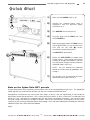
Quick Start
1
1)
Make sure the POWER switch is off.
2)
Connect the supplied power cord in
compliance with the Important Safety
Instructions on 3.
3)
Turn MASTER level to minimum (1).
4)
Plug your guitar into the INPUT jack, then
switch POWER on.
5)
While playing guitar, adjust the TRIM level so
that the green LEDS
are on most of the
time and the red LED
flashes
occasionally at peak playing levels.
2
3
Set MASTER to desired level.
4
6)
5
6
Rotate the DATA WHEEL to explore Amp
Design presets. Amp settings and internal
circuitry will change automatically! (You will
hear the presets change instantly, before the
motorized knobs “catch up.”)
NOTE: You can interrupt the motorized
rotation of a knob simply by grabbing it and
turning it.
7)
Turn to page 8 for an overview of the basic
operation of your Cyber–Twin SE™.
Note on the Cyber–Twin SE™ pr esets
Custom Shop presets were created by various players fluent in the corresponding musical styles. The appropriate
model of guitar was used wherever possible, ala Jimi with a maple-necked Stratocaster®.
Consequently, some presets may seem to be more “trebly” or “bassy” than you would prefer, or seem louder or
quieter than some of the other presets. This is natural, because if person “A” plays a Telecaster® in a tiled room, and
person “B” uses a Jazz guitar in a carpeted room, they will achieve very different end results. You can easily move
the knob settings and store your changes if desired. Most of our Cyber-presets are designed to let the unique
character of your instrument and playing style come through. That’s why thousands of pros and hobbyists alike have
added the Cyber-Twin® SE to their tone toolbox!
Enjoy!
w w w.f e n d e r.com
✧
w w w. m r g e a r h e a d .net
6
Fender ® Cyber–Twin ® SE Amplifier
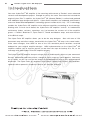
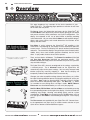
Introduction
Your new Cyber-Twin ® SE amplifier is the crowning achievement of Fender’s most advanced
research and development project. Brought to you by the same Tone–team that created the
original Cyber–Twin™ amplifier, the Cyber-Twin ® SE (Second Edition) is refined and updated
with additional amp designs and effects. Cyber–Series amplifiers are endowed with Fender’s
exclusive Virtual Tone Interpolation™ technology (patent number 6,222,110). VTI™ technology
enables the Cyber-Twin® SE amplifier to be different amplifiers according to circuit design.
Starting with a virtual circuit board, the Cyber-Twin ® SE amplifier "rewires" its fundamental
architecture (tubes, resistors, capacitors, etc.) to become the essence of all the amplifier
greats — Fender’s Blackface™, Dyna–Touch™, Tweed and Modern amps, and even the best
of the British amps!
The Cyber-Twin® SE amplifier allows you to be the amp designer.
Start with one of 150
permanent amp and effect setups stored within the Cyber-Twin ® SE amp—twist some knobs,
make some changes, then SAVE to one of the 100 rewritable preset locations reserved
onboard for your original amplifier designs.
MIDI implementation on the Cyber-Twin® SE
amplifier enables you to transfer presets to and from the amp for backup to a PC, or for
exchange with other Cyber-Twin ® SE amplifier players.
The Cyber-Twin® SE amplifier also puts a huge array of studio–quality effects at your command:
Reverb, Modulation and Delay effects, enough to satisfy most any sonic appetite. And many
are in stereo, so you can use the line outputs or headphones to enjoy a fully ambient stereo
dimension. The Cyber-Twin® SE amplifier’s Dyna–Touch™ power amp circuitry and Celestion ®
speakers deliver powerful, responsive Tone to you and your audience.
Thank you for choosing Fender®
— To n e , Tr a d i t i o n a n d I n n o v a t i o n — s i n c e 1 9 4 6
w w w.f e n d e r.com
✧
w w w. m r g e a r h e a d .net
Fender ® Cyber–Twin ® SE Amplifier
7
C y b e r - Tw i n ® S E A m p l i f i e r F e a t u r e s
• 40 character display shows you menu options, prompts and amp design information
• The data wheel enables you to select a dynamic range of settings
• 5 modes of operation: •Play •Amp Edit •FX Edit •Utility •Tuner
• 8 motorized knobs automatically rotate to adjust to preset selections, MIDI continuous controller
sequences and input from a MIDI pedal or analog expression pedal
• 250 amplifier design presets:
• Fender Custom Shop – 100 custom amp designs including effects
• Player’s Lounge – 100 of your own (rewritable) amp and effects designs
• Your Amp Collection – 50 classic amp designs as originally manufactured
• MIDI implementation:
• 24 continuous controllers for automatic, sequenced control of amplifier settings
• An assignable continuous controller for remote control of a dynamic parameter
• 4 system exclusive functions for transferring presets and updating systems
• 16 drive circuitry selections: • 12 tube types, • 4 solid state types including new Extreme setting
• 2 vacuum tubes are used in the tube drive and the analog circuitry, (12AX7WC), now externally accessible
• 6 tone stacks, each with 2 location parameters (before/after the drive circuitry)
• 43 FX (effects) selections with 4–5 adjustable parameters each:
• 10 delay FX • 11 modulation FX • 3 special FX • 4 FX combinations • 14 new FX
• 11 Reverb types with 4 adjustable parameters each
• 4 compression level settings
• A hum reduction button to reduce line noise
• 3 noise gate levels with an adjustable depth parameter
• 8 timbre types give instant tone shaping for style accent or balance
• 4 line/speaker phase settings allow you to reverse the polarity of each speaker independently
• 8 reverb/effects bypass combinations (or vibratone rotor speed) that you can toggle by footswitch
• 4 quick access keys for one button access to favorite amp design presets
• 4 button footswitch for hands free selection of your quick access presets
• The expression pedal jack allows you to control nearly every preset controllable parameter with an analog
expression pedal (optional)
• 130 watts of stereo output power, (65 watts per channel)
• Two 12AX7 preamp tubes
• Two 12 inch, 8 ohm Celestion® G12T-100 speakers
• 1 stereo digital line output, RCA SPDIF jack for connection to digital sound equipment
• 2 stereo XLR impedance balanced output jacks, with mono/stereo selection switch
• 3 effects loop jacks (mono out, and mono or stereo in) with -10dbv/+4dbu switch
• 2 speaker extension jacks for experimenting with other external speaker cabinets
w w w.f e n d e r.com
✧
w w w. m r g e a r h e a d .net
8
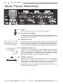
Front Panel Overview
1 ✧ Over view
This page introduces key concepts for the basic operation of your
Cyber–Twin SE™. The following pages provide an overview of each item
on the front and rear panels.
The DISPLAY shows vital information and menus for the Cyber-Twin® SE.
The DATA WHEEL works dynamically with the display giving you full control
over preset selection, effect parameters and system configuration. The
display also responds to the use of panel knobs or buttons providing
useful information. You can enter different MODES to edit amplifier designs,
effects and system utilities; each mode determines the functions of the
display and data wheel.
PLAY MODE is active whenever the Cyber-Twin® SE amplifier is first
switched on. After booting up, the display will show information about the
current preset. The first line displays the preset location (bank/number)
and name. The second line displays the type of tone stack controls (treble,
middle, bass), tone stack location (pre/post distortion) and the active
effect. In play mode, the data wheel selects presets.
Each preset contains a complete set
of amplifier and effects settings.
There are three banks of PRESETS. The FENDER CUSTOM SHOP (C00-C99)
and YOUR AMP COLLECTION (A00-A49) are permanent presets. The
PLAYER’S LOUNGE (P00-P99) presets are rewritable for you to save your own
amp and effect designs.
The Cyber-Twin® SE is instantly reconfigured to the settings saved within
a selected preset. The 8 MOTORIZED knobs on the Cyber-Twin® SE
automatically adjust to the preset settings. You can safely interrupt knob
rotation anytime by manually stopping it. Note that the display will
temporarily indicate knob position when turned manually.
Changes you make to amplifier settings (volume, tone, effects, etc.) will be
lost upon selecting a different preset or turning the amplifier off, unless you
save them. SAVE simply by pressing SAVE, selecting a Player’s Lounge
preset to overwrite and pressing SAVE again. The SAVE LED
blinks
as a reminder to save settings once a change is made. NOTE: MEMORY
PROTECTION must be disabled before you can save! (see page 24).
AMP EDIT MODE, FX EDIT MODE and UTILITY MODE are activated by pressing
the corresponding buttons to the right of the display. Use these modes for
modifying amp design, selecting and editing effects and for system
management. TUNER MODE is activated using the TUNER button; use it to
tune your guitar. PLAY MODE is reactivated by pressing EXIT. Use it to play
guitar!
Two FOOTSWITCHES are supplied with your Cyber-Twin® SE. Connect them
to the appropriate rear panel jacks to enable remote selection of your
Quick Access buttons and Reverb/Effects bypass.
w w w.f e n d e r.com
✧
w w w. m r g e a r h e a d .net
Front Panel Overview
9
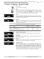
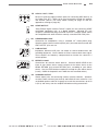
F ront Panel Overview
A. INPUT JACK
Input connection for your guitar.
B. TRIM
Sets the input signal level for proper analog–to–digital conversion. Adjust
TRIM so that most of the green LEDs
stay on at normal playing
levels and the red LED
flashes occasionally while playing at peak
intensity. This knob is not preset programmable nor motorized.
C. GAIN
Adjusts the distortion level and contributes to overall amplifier loudness.
Use VOLUME {D} to compensate for any undesired volume level change
resulting from a GAIN level change.
D. VOLUME
Adjusts the post–distortion signal level and contributes to overall amp
loudness. Use in conjunction with GAIN {C} to normalize volume
differences between presets.
Several knobs affect the overall loudness of the amplifier:
Knob
Function
TRIM
GAIN
VOLUME
MASTER
Supply proper signal level to DSP
Adjust distortion level
Equalize level differences between presets
Global volume and maximum level governing
Preset
Programmable
MIDI
Controllable
Expression Pedal
Controllable
NO
YES
YES
NO
NO
YES
YES
YES
NO
YES
YES
YES
E. TREBLE / MIDDLE / BASS
Adjusts tone in the high–, mid–, and low–frequency ranges respectively.
F. PRESENCE
Adjusts tone in the ultra-high frequency range after the distortion circuitry
for a crisp tone sparkle.
G. REVERB
Adjusts the level of the active Reverb. Enter AMP edit mode to select
Reverb types and edit Reverb parameters (see page 14).
H. MASTER VOLUME
Controls the overall loudness of the amplifier globally, independent of any
preset. MASTER VOLUME is not preset programmable, although it is
motorized so that it can be controlled remotely by expression pedal or MIDI.
Remote operation of MASTER VOLUME is limited to a maximum value
defined by where the MASTER VOLUME is set manually on the front panel.
Set the MASTER VOLUME knob to the desired maximum level and
motorized control will be confined to the range below that boundary.
w w w.f e n d e r.com
✧
w w w. m r g e a r h e a d .net
10
Front Panel Overview
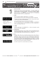
I. QUICK ACCESS
Provides instant access to four favorite presets. To assign a button, first
select the preset with the data wheel. Then, press and hold a QUICK
ACCESS button. The LED
lights up when your new QUICK ACCESS
button has been activated. Press the same button or corresponding
footswitch button to recall the assigned preset.
J. SAVE
Saves the current amplifier configuration as a new preset.
Use MIDI to transfer presets to
and from a computer.
Organize presets in the Player’s
Lounge by using SAVE to move
(copy) presets.
1) Press SAVE once and a Player’s Lounge preset location is displayed.
2) Select any Player’s Lounge preset to overwrite using the data wheel.
Press EXIT to cancel the save operation
3) Press SAVE again and your new preset will be stored.
The SAVE LED flashes after an amp setting is changed as a reminder to
save. If a different preset is selected before the current configuration is
saved, your changes will be lost.
K. TUNER
Turns the tuner on/off. The TUNER LED
while the tuner scale is displayed.
flashes and audio is muted
L. NOISE GATE
Turns the noise gate on/off. Use it to reduce static and environmental noise
transmitted through nearby electronic devices. Enter AMP edit mode to
edit noise gate depth and threshold parameters (see page 14).
M. TAP
In PLAY mode, TAP sets the time/rate interval of the active effect, if
applicable. Press TAP at least twice at the desired rate to set the interval
by feel (the average of the last five taps is calculated for multiple taps).
Press TAP once for the longest interval possible. The TAP LED
flashes
at the interval rate which is also temporarily displayed. Adjust the time/rate
parameter accessed in the FX edit mode for precision control of the TAP
interval (see the FX menus on page 16 for details).
In UTILITY mode, TAP is used to confirm menu actions.
w w w.f e n d e r.com
✧
w w w. m r g e a r h e a d .net
Front Panel Overview
11
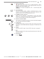
N. PEAK and MIDI LEDs
PEAK flashes when the DSP circuit is clipping (distorting). Reduce
VOLUME if undesirable distortion is heard while this LED is on, then use
MASTER to the increase loudness level.
MIDI is on when the Cyber–Twin SE™ is communicating MIDI
information.
O. HUM REDUCTION
Turns hum reduction on/off. Reduces environmental hum in some
situations using a patented algorithm that seeks out line frequencies and
squelches only the hum, without degrading your music!
P. FX LEVEL / FX VAL 1 / FX VAL 2
Adjusts the level, parameter 1 and parameter 2 of the active effect,
respectively. The functions of these knobs as well as additional parameters
can be accessed through the FX edit mode (see page 16).
Q. DISPLAY and DATA WHEEL
Your interface for controlling the dynamic functions described throughout
this manual (See the Overview on page 8).
R. PRESET EDIT
The AMP and FX buttons activate the AMP and FX (effects) edit modes
respectively. For the AMP edit menus see page 14; FX edit menus see
page 16.
S. UTILITY
Activates the UTILITY mode. For the UTILITY edit menus, see page 24.
T. EXIT
Activates the default PLAY mode (except during factory preset restore and
MIDI data transfers).
U. BLUE JEWEL
It’s still a
w w w.f e n d e r.com
✧
w w w. m r g e a r h e a d .net
12
Rear Panel Overview
Rear Panel Overview
AA. POWER
Switches Power on or off to the Cyber-Twin® SE amplifier.
BB. IEC POWER CORD SOCKET
Connection for the included power cord. Connect to a grounded AC outlet
in accordance with the voltage and frequency ratings listed on the rear
panel of your Cyber–Twin SE™.
CC. FOOTSWITCH JACK
Connect the included Fender® 4–button footswitch using the MIDI type
cable provided. Use this footswitch to remotely activate the Quick Access
presets. Although the footswitch uses a MIDI type cable, the footswitch is
an analog device and should only be connected to the FOOT SWITCH jack.
DD. EXPRESSION PEDAL JACK
Connection for a standard expression foot pedal (optional) used to remotely
control any of the following parameters: GAIN, VOLUME, TREBLE,
MIDDLE, BASS, PRESENCE, REVERB, MASTER, any Reverb parameter, or
any effect parameter.
Expression pedal assignment is preset
programmable through the AMP edit mode (see page 15).
EE. REVERB / FX BYPASS
Connection for the included one-button footswitch. Use this footswitch to
remotely bypass Reverb and/or effects in one of 8 input/output
configurations. Or, if Vibratone is the active effect, you can switch between
rotor speeds (set Reverb/FX bypass parameter to Vibro Fast/Slow).
Reverb/FX bypass is preset programmable through the AMP edit menu (see
REVERB / FX BYPASS on page 15)
w w w.f e n d e r.com
✧
w w w. m r g e a r h e a d .net
Rear Panel Overview
13
FF. MIDI IN / OUT / THRU
Musical Instrument Digital Interface ports for connecting MIDI devices to
the Cyber–Twin SE™. MIDI can be used to remotely control the amplifier
and transfer presets (see Utility Mode starting on page 24 and the
appendices starting on page 26).
GG. SPDIF OUTPUT
“Sony/Phillips Digital Interface Format” output jack for connecting SPDIF
compatible equipment such as a digital recorder. Although this jack
accepts a standard RCA plug, the SPDIF OUTPUT is a digital stereo source
not compatible with other functions normally associated with RCA jacks.
HH. HEADPHONES JACK
Connection for headphones using a standard 1/4˝ stereo phone plug.
Speaker outputs (internal and rear panel jacks) are automatically muted, but
LINE OUTPUT jacks are not.
II. LINE OUTPUT
Impedance balanced XLR jacks for output to sound reinforcement and
recording equipment. Use the button to select stereo or dual mono signal.
These outputs are frequency compensated to simulate the sound of a
miked speaker.
JJ. EFFECTS LOOP
Connections for external effects devices. Connect MONO SEND to the
input of your effects device and the output of the effects device to the
MONO RETURN jack or both RETURN jacks, according to your effects
device. Use the LEVEL button to optimize the loop for your effects device
(usually –10dBv for footpedals and +4dBu for rack mounted effects).
KK. SPEAKER OUTPUT
Stereo output jacks for connecting external speaker cabinets. Speakers
must be 8–ohm minimum (per channel) and handle 65 watts minimum. Use
unshielded speaker cable of 16–gauge or heavier for connections up to 50
ft (15 m) and always turn the amplifier off before making connections.
w w w.f e n d e r.com
✧
w w w. m r g e a r h e a d .net
14
Amp Edit Mode
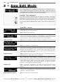
2 ✧ Amp Edit Mode
This chapter explains how to navigate the Amp Edit menus and defines each
of the 17 Amp Edit parameters and their value ranges. Note that Reverb is
considered part of the amplifier and is included in the Amp Edit menu to provide
more options for using Reverb and effects simultaneously.
Amp Edit – Menu Navigation
Press AMP to activate Amp Edit mode and display a parameter. Press AMP
repeatedly to display each parameter in a continuous loop, or press and hold
AMP while turning the data wheel to move through the list in either direction.
Use the data wheel to edit parameter values. Press EXIT to return to Play
mode.
Amp Edit – Menus
Change the name of a preset. Use the FX VAL2 knob to move the blinking cursor
and the data wheel to select characters.
NAME CHANGE
Values: Alphanumeric characters
Selects tone stack (TREBLE, MIDDLE and BASS) type: British—vintage UK style;
Tweed—Fender Tweed amps; Blackface—Fender Blackface amps; Modern—broad
spectrum tone stack with capabilities new to guitar amps; NeoBritish—modern UK
style; Dyna–Touch—dirty channel of Fender Dyna-Touch series amplifiers
TONE STACK TYPE
Values: Tweed
Blackface
British
Modern
NeoBritish
Dyna–Touch
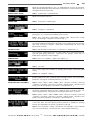
Tone stack location, before or after distortion in the signal path.
TONE STACK LOCATION
Values: Pre–Distortion
Post–Distortion
Selects drive circuitry type. Blackface Tube and Tweed Tube offer cleaner sounds,
while others produce high gain sounds. Each drive type has 3 increasing gain levels.
Blackface—Fender Blackface amps; Tweed—Fender Tweed amps; Hot Rod—
Fender Hot Rod amps; HMB—typical UK style; Dyna–Touch—Fender Dyna–Touch
amps; Extreme—extreme high gain
DRIVE CIRCUITRY
Values: Blackface Tube (1/2/3)
Tweed Tube (1/2/3)
HMB Tube (1/2/3)
Dyna–Touch (1/2/3)
Extreme
Hot Rod Tube (1/2/3)
Selects Reverb type. Small Ambience—, Small/Large Room—, Large Hall—, and
Arena—simulate the acoustics of different sized spaces. Small/Large Plate—studio
Reverb that generates bright timbres yet retains warmth. Blackface Reverb—classic
Fender spring Reverb. Gated—Unique modern Reverb, see Reverb Tone/Shape
menu below. Fender Reverb—classic 1963 tube driven unit uniquely located predistortion, see Reverb In Level/Dwell menu below.
REVERB TYPE
Values: Small Room
Plate
Large Plate
Reverb
Large Room
Small Hall
Blackface Reverb
Gated
Large Hall
Arena
Small
Small Ambience
Fender
Adjusts the Reverb circuit input level rather than the output level (which is controlled
by the front panel REVERB knob). If Fender Reverb is the active Reverb type, this
parameter is called Reverb Dwell.
REVERB IN LEVEL / DWELL
Values: 1.0 (minimum)
w w w.f e n d e r.com
✧
10.0 (maximum)
w w w. m r g e a r h e a d .net
Amp Edit Mode
15
Adjusts the Reverb high–frequency tone. Or, if Gated Reverb is active, this parameter
adjusts Reverb Shape with which radical decay characteristics can be achieved such as
rectangular, linear and reverse tails.
REVERB TONE / SHAPE
Values: 1.0 (minimum)
10.0 (maximum)
Adjusts the Reverb sustain time.
REVERB TIME
Values: 1.0 (shortest)
10.0 (longest)
Adjusts the Reverb decay from a sparse/irregular sound to a dense/smooth sound.
REVERB DIFFUSION
Values: 1.0 (sparse)
10.0 (dense)
Shifts the equalization of the amplifier providing instant tone shaping to accommodate
playing styles or to compensate for different room acoustics.
TIMBRE
Values: None
Full Body
Razor Edge
Bright & Light
Scoop
Super Bright
Squawk
Acoustic Scoop
Bass Booster
Drop
Selects the phase polarity (push/pull or pull/push) for each speaker. Fender amps with
Reverb have traditionally had speakers operating in reverse polarity due to the extra tube
gain stage necessary for Reverb. Useful when experimenting with stereo mike
placement in the studio.
SPEAKER PHASE
Values: Both Standard
Both Reverse
Left Reverse
Right Reverse
Use to compress (moderate) the range of volume output due to extremes between soft
and loud guitar playing intensities. Compression also provides sustain and is a
fundamental component of many amplifiers.
COMPRESSION
Values: Off
Low
Medium
High
Even Higher
Use to set the frequency cut–off boundary for the noisegate when it is activated.
NOISEGATE DEPTH
Values: 1.0
10.0
Use to set the signal level sensitivity for activating the noisegate. Affected by TRIM
setting.
NOISEGATE THRESHOLD
Values: Low
Medium
High
Assigns a parameter to be controlled by an expression pedal (optional). Parameters in
[brackets] appear only when a particular effect or Reverb is active. For a list of effects
parameters, see page 16, for Reverb parameters, see above.
EXPRESSION PEDAL ASSIGNMENT
Values: Volume Gain Treble Middle Bass Presence Reverb [FX Level]
[FX Val 1]
[FX Val 2]
[FX Val 3]
[FX Val 4]
Master Volume
Reverb In Level
[Dwell]
Reverb Tone [Shape]
Reverb Time
Reverb Diffusion
Assigns a parameter to be controlled by a MIDI continuous controller pedal (optional).
Parameters in [brackets] appear only when a particular effect or Reverb is active. For
effects types/parameters, see page16, for Reverb types/parameters, see above.
CONT. CONTROLLER ASSIGNMENT
Values: Volume Gain Treble Middle Bass Presence Reverb [FX Level]
[FX Val 1]
[FX Val 2]
[FX Val 3]
[FX Val 4]
Master Volume
Reverb In Level
[Dwell]
Reverb Tone [Shape]
Reverb Time
Reverb Diffusion
Use to bypass the in or out signals for Reverb “tail” and/or effects. Or, when Vibratone
is the active effect, the Rotor Speed Fast/Slow parameter is available for switching
between two (adjustable) rotor speeds (see Vibratone, page 20).
REVERB / FX BYPASS
Values: FX In Reverb In
Out
FX Out & Reverb In
w w w.f e n d e r.com
✧
FX Out Reverb Out FX & Reverb In FX In & Reverb
FX & Reverb Out
[Rotor Speed Fast/Slow]
w w w. m r g e a r h e a d .net
16
FX Edit Mode
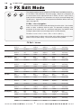
3 ✧ FX Edit Mode
This chapter explains how to navigate the FX Edit menus and defines each of
the 43 effects, their parameters and value ranges. Note that 3 parameters of
the active effect can be adjusted with the FX LEVEL, FX VAL 1 and FX VAL 2
knobs, but the remaining 2 or 3 parameters can only be accessed through the
FX edit menus. A glossary of effect and parameter definitions follows the menu
table, (see page 19).
FX Edit – Menu Navigation
Press FX to activate FX Edit mode and display the active effect. Use the data
wheel to select a different effect or press FX repeatedly to display each
parameter of the active effect in a continuous loop (press and hold FX while
turning the data wheel to move through the list in either direction).
FX Select
Level
Val 1
Val 2
Val 3
Val 4
(Val 5)
Use the data wheel to adjust values of the active effect parameter (or select
effects in the FX Select menu). Press EXIT to return to Play mode.
FX Edit – Menus
Mono Delay
Dotted 8/16 Delay
One-E-Da-Delay
Ping-Pong Delay
Swing Tap Delay
Tape Echo
Stereo Tape Echo
Stereo Flam Delay
Ducking Delay
Backwards Delay
Delay
Out Level
Delay
Time
Delay
Feedback
Delay
Brightness
Delay
In Level
Delay
Time Change
1.0-10.0
30-1450 ms
1.0-10.0
1.0-10.0
1.0-10.0
Ramp or Step
Delay
Out Level
Delay
Time
Delay
Feedback
Delay
Brightness
Delay
Stereo
Delay
Time Change
1.0-10.0
30-1450 ms
1.0-10.0
1.0-10.0
1.0-10.0
Ramp or Step
Delay
Out Level
Delay
Time
Delay
Feedback
Delay
Brightness
Delay
Stereo
Delay
Time Change
1.0-10.0
30-1450 ms
1.0-10.0
1.0-10.0
1.0-10.0
Ramp or Step
Delay
Out Level
Delay
Time
Delay
Feedback
Delay
Brightness
Delay
Stereo
Delay
Time Change
1.0-10.0
30-1450 ms
1.0-10.0
1.0-10.0
1.0-10.0
Ramp or Step
Delay
Out Level
Delay
Time
Delay
Feedback
Delay
Brightness
Delay
Stereo
Delay
Time Change
1.0-10.0
30-1450 ms
1.0-10.0
1.0-10.0
1.0-10.0
Ramp or Step
Echo
Out Level
Echo
Time
Echo
Feedback
Echo
Wow&Flutter
Echo
Brightness
Echo
Time Change
1.0-10.0
30-1450 ms
1.0-10.0
1.0-10.0
1.0-10.0
Ramp or Step
Echo
Out Level
Echo
Time
Echo
Feedback
Echo
Wow&Flutter
Echo
Brightness
Echo
Time Change
1.0-10.0
30-1450 ms
1.0-10.0
1.0-10.0
1.0-10.0
Ramp or Step
Delay
Out Level
Delay
Time
Delay
Feedback
Delay
Brightness
Delay
Stereo
Delay
Time Change
1.0-10.0
30-1450 ms
1.0-10.0
1.0-10.0
1.0-10.0
Ramp or Step
Delay
Out Level
Delay
Time
Delay
Feedback
Delay
Release
Delay Ducking
Threshold
Delay
Time Change
1.0-10.0
30-1450 ms
1.0-10.0
1.0-10.0
1.0-10.0
Ramp or Step
Delay
Out Level
Delay
Time
Delay
Forward Feedback
Delay
Reverse Feedback
Delay
Brightness
Delay
Time Change
1.0-10.0
30-1450 ms
1.0-10.0
1.0-10.0
1.0-10.0
Ramp or Step
w w w.f e n d e r.com
✧
w w w. m r g e a r h e a d .net
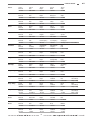
FX Edit Mode
Tremolo
Amp Tremolo
Auto Pan
Phaser
Vibratone
Pedal Wah
Touch Wah
Sine Chorus
Triangle Chorus
Sine Flange
Triangle Flange
Delay + Chorus
Delay + Flange
Delay + Phaser
AutoSwell +
Chorus
Ultra-Clean +
Chorus
Pitch Shift
Tremolo
Out Level
Tremolo
Rate
Tremolo
Depth
Tremolo
Offset
Tremolo
Shape
1.0-10.0
0.08-10.0Hz
1.0-10.0
1.0-10.0
1.0-10.0
Tremolo
Out Level
Tremolo
Rate
Tremolo
Depth
Tremolo
Duty Cycle
Tremolo
Shape
1.0-10.0
0.08-10.0Hz
1.0-10.0
1.0-10.0
1.0-10.0
Pan
Out Level
Pan
Rate
Pan
Depth
Pan
Shape
Pan
Phase
1.0-10.0
0.08-10.0Hz
1.0-10.0
1.0-10.0
1.0-10.0
Phaser
Out Level
Phaser
Rate
Phaser
Depth
Phaser
Feedback
Phaser
Stereo
1.0-10.0
0.08-10.0Hz
1.0-10.0
1.0-10.0
1.0-10.0
Vibratone
Out Level
Rotor
Speed
Vibratone
Doppler
Rotor Frequency
Speed 1
Rotor Frequency
Speed 2
1.0-10.00
0.08-10.0Hz
1.0-10.0
0.08-10.0Hz
0.08-10.0Hz
Wah
Out Level
Wah
Wah
Heel Frequency
Wah
Toe Frequency
Wah
Sweep Type
1.0-10.0
1.0-10.0
1.0-10.0
1.0-10.0
The Babys Cryin’ or The Real McCoy
Wah
Out Level
Wah
Sensitivity
Wah Minimum
Frequency
Wah Maximum
Frequency
Wah
Peak
1.0-10.0
1.0-10.0
1.0-10.0
1.0-10.0
LowQ or HighQ
Chorus
Out Level
Chorus
Rate
Chorus
Depth
Chorus
Average Delay
Sine Chorus
Phase
1.0-10.0
0.08-10.0Hz
1.0-10.0
1.0-10.0
1.0-10.0
Chorus
Out Level
Chorus
Rate
Chorus
Depth
Chorus
Average Delay
Tri-Chorus
Phase
1.0-10.0
0.08-10.0Hz
1.0-10.0
1.0-10.0
1.0-10.0
Flange
Out Level
Flange
Rate
Flange
Depth
Flange
Feedback
Sine Flange
Phase
1.0-10.0
0.08-10.0Hz
1.0-10.0
1.0-10.0
1.0-10.0
Flange
Out Level
Flange
Rate
Flange
Depth
Flange
Feedback
Tri-Flange
Phase
1.0-10.0
0.08-10.0Hz
1.0-10.0
1.0-10.0
1.0-10.0
FX Wet
Out Level
Delay
Time
Chorus
Depth
Delay
Feedback
Chorus
Rate
Delay
Time Change
1.0-10.0
30-1450 ms
1.0-10.0
1.0-10.0
0.08-10.0Hz
Ramp or Step
FX Wet
Out Level
Delay
Time
Flange
Depth
Delay
Feedback
Flange
Rate
Delay
Time Change
1.0-10.0
30-1450 ms
1.0-10.0
1.0-10.0
1.0-10.0
Ramp or Step
FX Wet
Out Level
Delay
Time
Phaser
Depth
Delay
Feedback
Phaser
Rate
Delay
Time Change
1.0-10.0
30-1450 ms
1.0-10.0
1.0-10.0
1.0-10.0
Ramp or Step
FX Wet
Out Level
AutoSwell
Attack Time
Chorus
Depth
AutoSwell
Sensitivity
Chorus
Rate
1.0-10.0
1.0-10.0
1.0-10.0
1.0-10.0
0.8-10.0 Hz
FX Wet
Out Level
Chorus
Rate
Chorus
Depth
Body
Brilliance
1.0-10.0
30-1450 ms
1.0-10.0
1.0-10.0
1.0-10.0
Pitch Shift
Out Level
Pitch
Pitch
Detune
Pitch
Feedback
Pitch
Pre-Delay
1.0-10.0
1.0-10.0
1.0-10.0
1.0-10.0
1.0-10.0
w w w.f e n d e r.com
✧
17
w w w. m r g e a r h e a d .net
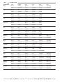
18
Ring Modulation +
Delay
FX Edit Mode
FX Wet
Out Level
Modulator
Frequency
Delay
Out Level
Delay
Time
Delay
Feedback
Delay
Time Change
1.0-10.0
0.08-10.0Hz
1.0-10.0
30-1450 ms
1.0-10.0
Ramp or Step
Delay
Out Level
Delay
Time
Delay
Feedback
Delay
Brightness
Delay
In Level
1.0-10.0
30-1450 ms
1.0-10.0
1.0-10.0
1.0-10.0
Fuzz
Out Level
Fuzz
Gain
Octave
Level
Low
Frequency
High
Frequency
1.0-10.0
1.0-10.0
1.0-10.0
1.0-10.0
1.0-10.0
Resolver
Out Level
Resolver
Depth
Resolver
Tone
Resolver
Attack
Resolver
Release
1.0-10.0
1.0-10.0
1.0-10.0
1.0-10.0
1.0-10.0
Pitch Shift
Out Level
Pitch
Pitch
Pre-Delay
Pitch Heel
Limit
Pitch Toe
Limit
1.0-10.0
1.0-10.0
1.0-10.0
1.0-10.0
1.0-10.0
Overdrive
Out Level
Overdrive
Gain
Overdrive
Bass
Overdrive
Middle
Overdrive
Treble
1.0-10.0
1.0-10.0
1.0-10.0
1.0-10.0
1.0-10.0
Alienator
Out Level
Alienator
Content
Heel
Range Limit
Toe
Range Limit
Alienator
Shape
1.0-10.0
1.0-10.0
1.0-10.0
1.0-10.0
1.0-10.0
Pedal Wah +
Delay
Delay
Out Level
Delay
Time
Delay
Feedback
Wah
Delay
Brightness
Delay
Time Change
New!
1.0-10.0
30-1450 ms
1.0-10.0
1.0-10.0
1.0-10.0
Ramp or Step
Touch Wah +
Delay
Delay
Out Level
Delay
Time
Wah
Sensitivity
Wah
Peak
Delay
Feedback
Delay
Time Change
New!
1.0-10.0
30-1450 ms
1.0-10.0
LowQ or HighQ
1.0-10.0
Ramp or Step
Fuzz +
Pedal Wah
Fuzz
Out Level
Fuzz
Gain
Wah
Heel
Frequency
Toe
Frequency
New!
1.0-10.0
1.0-10.0
1.0-10.0
1.0-10.0
1.0-10.0
Fuzz +
Touch Wah
Fuzz
Out Level
Fuzz
Gain
Wah
Sensitivity
Octave
Level
Wah
Peak
New!
1.0-10.0
1.0-10.0
1.0-10.0
1.0-10.0
LowQ or HighQ
Fuzz +
Delay
Fuzz
Out Level
Fuzz
Gain
Delay
Out Level
Delay
Time
Delay
Feedback
Delay
Time Change
New!
1.0-10.0
1.0-10.0
1.0-10.0
30-1450 ms
1.0-10.0
Ramp or Step
Octave +
Tape Echo
Lower Octave
Out Level
Echo
Out Level
Echo
Time
Echo
Feedback
Echo
Wow & Flutter
Echo
Time Change
New!
1.0-10.0
1.0-10.0
30-1450 ms
1.0-10.0
1.0-10.0
Ramp or Step
MidBoost +
Tape Echo
MidBoost
Out Level
MidBoost
Frequency
Echo
Out Level
Echo
Time
Echo
Feedback
Echo
Time Change
New!
1.0-10.0
1.0-10.0
1.0-10.0
30-1450 ms
1.0-10.0
Ramp or Step
Overdrive +
Tape Echo
Overdrive
Level
Overdrive
Gain
Echo
Out Level
Echo
Time
Echo
Feedback
Echo
Time Change
New!
1.0-10.0
1.0-10.0
1.0-10.0
30-1450 ms
1.0-10.0
Ramp or Step
None
None
Auto Pan Delay
New!
Fuzz
New!
Resolver
New!
Pedal Pitcher
New!
Overdrive
New!
Alienator
New!
w w w.f e n d e r.com
✧
w w w. m r g e a r h e a d .net
FX Edit Mode
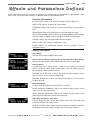
19
E ffects and Parameters Defined
NOTE: Most effects have the same types of parameters in common and they are defined as a group below. Some
effects have unique parameters and they are defined under the corresponding effect.
Common Parameters
IN / OUT LEVEL—Adjusts the effect circuit input or output signal level.
TIME / RATE—Adjusts an interval or cycle duration.
FEEDBACK—Adjusts how much of the effect circuit output is returned to its
input.
BRIGHTNESS—Adjusts the effected tone in the high-frequency range.
DELAY TIME CHANGE—Select Ramp for an analog sounding warble, or select
Step for a digital sounding zip when changing the delay time parameter.
STEREO—Adjusts the stereo separation between channels.
DEPTH—Adjusts the range of a modulation sweep.
PHASE—Adjusts the relationship between the two oscillators used in
modulation effects.
Effects Definitions
Mono Delay
The most basic single-tap digital delay effect.
Dotted 8/16, One-E-Da, Ping Pong, Swing Tap and Stereo Flam Delays
Multi–tap (multiple–output) stereo digital delays with various tap timings.
Ducking Delay
A mono delay with a special feature – while you are playing, your delayed
repeats are quiet or “duck” below the dry signal – when you stop playing, the
delayed repeats return to normal volume.
DUCKING DELAY RELEASE— Adjusts how long the delayed repeats wait to
return to normal volume after you stop playing.
DUCKING SENSITIVITY—Adjusts how loud your playing has to be to activate
the delay ducking.
Backwards Delay
A unique effect that repeats the delay intervals in reverse.
DELAY FORWARD FEEDBACK—Adjusts the number of delay repeats, all the
same as the first delay (reversed).
DELAY REVERSE FEEDBACK—Adjusts the number of delay repeats which
alternately reverse direction (forward and backward).
Tape Echo and Stereo Tape Echo
Two-tap, ping-pong delay effects that simulate mono and stereo tape echo
machines complete with wow & flutter.
WOW & FLUTTER—Adds random frequency response modulation and pitch
variation to simulate the unique characteristics of tape echo machines.
w w w.f e n d e r.com
✧
w w w. m r g e a r h e a d .net
20
FX Edit Mode
Sine Chorus and Triangle Chorus
Stereo effects that add a “swirling” effect (sine) or “transparent” effect (triangle)
with delay modulation used to “thicken” a sound.
Sine Flange and Triangle Flange
Stereo effects with feedback that add a “whooshing” effect (sine) or a sharper
“phasing” effect (triangle) with delay modulation.
Amp Tremolo and Tremolo
Modulates volume of the input signal. Amp Tremolo is vintage Fender
Blackface amplifier tremolo and Tremolo is a sine-wave effect approximating a
grid–bias tremolo or the repeat percussion of a Tweed Tremolux.
DUTY CYCLE—Adjusts the high to low interval ratio of the signal volume. (Amp
Tremolo only)
TREMOLO SHAPE—Adjusts tremolo character from smooth to choppy.
TREMOLO OFFSET—Adjusts the oscillator center frequency from extreme to
gentle signal modulation. (Tremolo only)
Auto Pan
A sine-wave left-right panning effect. A low frequency oscillator sweeps the
signal back and forth in the stereo field.
PAN SHAPE—Adjusts the Auto Pan waveform from smooth to choppy.
Pedal Wah
A traditional foot-operated wah controlled with an expression pedal (optional).
For best results, the optimal expression pedal specifications include passive,
10k to 250k ohms.
WAH—Adjusts the wah filter center frequency.
HEEL / TOE FREQUENCY—Adjusts the minimum and maximum frequency
limits. Use to control the functional range of your pedal.
SWEEP TYPE—Select The Baby’s Cryin’ (modern wah) or The Real McQ
(vintage wah).
Touch Wah
Touch Wah is a dynamic wah that varies according to playing strength and
volume level.
SENSITIVITY—Adjusts the Touch Wah sensitivity to changes in volume.
MINIMUM / MAXIMUM FREQUENCY—Adjusts the Touch Wah frequency at low
and high playing volumes respectively. These settings can be reversed so that
low volumes will start with a high frequency wah that decreases when volume
increases.
SWEEP TYPE—Select Low Q (smooth wah) or High Q (extreme wah).
Vibratone
Rotating speaker effect based on the CBS-era Fender Vibratone speaker with a
2–speed rotating baffle.
VIBRO DOPPLER—Adjusts the Doppler shift (pitch change) of baffle rotation.
ROTOR SPEED 1, 2—Sets alternate rotor speeds selectable with the Reverb/FX
Bypass footswitch: Select Vibratone as the active effect, then use the AMP
button to access the Reverb/FX Bypass menu. Select Vibro Fast/Slow.
w w w.f e n d e r.com
✧
w w w. m r g e a r h e a d .net
FX Edit Mode
21
Phaser
A 12 stage, stereo phaser effect.
Delay + Chorus
Combination mono digital delay and triangle chorus effect.
Delay + Flange
Combination mono digital delay and triangle flange effect.
Delay + Phaser
Combination mono digital delay and stereo phaser effect.
AutoSwell + Chorus
An automatically triggered volume swell (increase) effect with chorus. The swell
begins when you reach the selected volume threshold. Note that you must stop
playing momentarily for autoswell to reset.
AUTOSWELL ATTACK TIME—Adjusts the time the swell takes to reach full
volume.
AUTOSWELL SENSITIVITY—Adjusts the volume level at which the effect is
triggered.
UltraClean + Chorus
An ultra-clean guitar tone with triangle chorus. For best results, use with clean
amp settings and your guitar’s neck (rhythm) pickup.
BODY—Adjusts low frequency tone.
BRILLIANCE—Adjusts high frequency tone.
Pitch Shift
A semitone-variable pitch shifter and detuner.
PITCH—Adjusts the pitch shift value in semi-tone increments from: 1.0 (2
octaves below), to 5.5 (unison) to 10.0 (2 octaves above).
PITCH DETUNE—Adjusts the pitch shift offset in micro-tone increments from:
1.0 (semi-tone flat), to 5.5 (in tune), to 10.0 (semi-tone sharp).
PITCH PRE-DELAY—Adjusts the delay before the pitch-shifted signal is heard.
Ring Modulation + Delay
A ring modulator with mono delay. Ring modulator creates tones above and
below your original guitar signal.
MOD FREQUENCY—Adjusts the ring modulator frequency. Radical results can
be achieved by controlling this parameter with an expression pedal (optional).
Select Ring modulator as the active effect, then use the AMP button to access
the Expression Pedal Assignment menu. Select Mod Frequency.
w w w.f e n d e r.com
✧
w w w. m r g e a r h e a d .net
22
FX Edit Mode
New Effects
Auto Pan Delay
A digital delay with random auto-panning in the stereo field.
Fuzz
A classic 60’s–70’s distortion effect rich with overtones and sustain. The effect
includes an octave higher parameter which can be independently mixed in.
FUZZ GAIN—Adjusts the gain of the fuzz effect.
OCTAVE LEVEL—Adjusts the level of the octave up signal mixed in.
LOW FREQUENCY—Adjusts the low frequency tone of the fuzz effect.
HIGH FREQUENCY—Adjusts the high frequency tone of the fuzz effect.
Resolver
A low-fidelity effect that purposely reduces the quality of the input signal.
Effective for “lo–fi” filtering on song introductions, for example.
DEPTH—Adjusts the amount of signal degradation.
TONE—Adjusts the tone of the degraded signal.
ATTACK—Adjusts the amount of time it takes for the signal to reach full
degradation.
RELEASE—Adjusts the amount of time it takes for the signal to return from full
degradation.
Pedal Pitcher
An effect very similar to the Pitch Shift effect, optimized for dynamic control
with an expression pedal or continuous controller. With practice, “wammy bar”
effects can be created. This effect is positioned before distortion whereas the
Pitch Shift effect is post distortion.
PITCH—Smoothly adjusts the pitch shift value in semi-tone increments from:
1.0 (2 octaves below), to 5.5 (unison) to 10.0 (2 octaves above).
PITCH PRE-DELAY—Adjusts the delay before the pitch-shifted signal is heard.
HEEL LIMIT—Adjusts the minimum limit of pitch reached at the heel of the
pedal.
TOE LIMIT—Adjusts the maximum limit of pitch reached at the toe of the pedal.
Overdrive
A popular pre-distortion gain stage effect (like the green pedal you know and
love), with additional tone controls. Use this effect with the Reverb/FX Bypass
footswitch (assigned to “FX Input Only” in the Amp Edit Mode) to recreate a
“stompbox” setup.
GAIN—Adjusts the gain of the overdrive effect.
BASS—Adjusts the low frequency band of the overdriven signal.
MIDDLE—Adjusts the middle frequency band of the overdriven signal.
TREBLE—Adjusts the high frequency band of the overdriven signal.
w w w.f e n d e r.com
✧
w w w. m r g e a r h e a d .net
FX Edit Mode
23
Alienator
A strange effect similar to a random ring modulator that provides additional
tones reminiscent of sci-fi B-movies. This effect is optimized for expression
pedals or continuous controllers.
CONTENT—Adjusts the frequency range of the additionally generated tones.
HEEL RANGE LIMIT—Adjusts the minimum frequency limit of the content
parameter for pedal control.
TOE RANGE LIMIT—Adjusts the maximum frequency limit of the content
parameter for pedal control.
SHAPE—Adjusts the shape or taper of the content curve between the heel and
toe limits.
Pedal Wah + Delay and Touch Wah + Delay
New combination effects including pre-distortion pedal wah or touch wah
combined with a Mono Delay effect placed post-distortion.
Fuzz + Pedal Wah and Fuzz + Touch Wah
New combination effects including two pre-distortion effects, pedal wah or
touch wah combined with fuzz.
Fuzz + Delay
A new combination effect including pre-distortion fuzz combined with a Mono
Delay effect placed post-distortion.
Octave + Tape Echo
A combination effect with a pre-distortion octaver allowing a simultaneous mix
of an octave lower and dry signal combined with post-distortion tape echo.
Midboost + Tape Echo
A pre-distortion midboost effect voiced according to the active midboost circuit
used in the Eric Clapton Signature Stratocaster® guitar combined with a postdistortion tape echo.
MIDBOOST FREQUENCY—Adjusts the center frequency in the middle
frequency band of the midboost.
Overdrive + Tape Echo
A combination effect including pre-distortion “stompbox” overdrive and postdistortion tape echo.
w w w.f e n d e r.com
✧
w w w. m r g e a r h e a d .net
24
Utility Mode
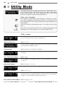
4 ✧ Utility Mode
This chapter explains how to navigate the Utility menus and describes each
of the 12 Utility parameters and their functions or value ranges. Utility mode is
used for MIDI functions and system management and all utility mode
parameters are global in scope (not affected by presets).
Utility – Menu Navigation
Press UTILITY to activate Utility mode and display a parameter or function.
Press UTILITY repeatedly to display each parameter in a continuous loop, or
press and hold UTILITY while turning the data wheel to move through the list in
either direction.
Use the data wheel to edit parameter values. Press EXIT to return to Play
mode.
Press TAP to activate special functions such as restoring factory presets and
dumping presets or utility settings to a PC or another Cyber-Twin® SE.
Utility – Menus
Disable/enable the SAVE button. When on prevents accidental overwriting of stored
presets. Upon first power up, this feature is defaulted to on.
MEMORY PROTECTION
Values: On
Off
Include or bypass pre-amplifier, onboard effects and tone processing in the S/PDIF
output signal for direct digital recording.
S/PDIF PATCHING
Values: Amp Line Out
Guitar Direct Out (bypass)
Select a MIDI continuous controller number to match your device. Many CC pedals use
11 (default).
CONT. CONTROLLER NUMBER
Values: 1–100
Sets the amplifier to receive MIDI information on all channels (default), one channel, or
no channels.
MIDI RECEIVE CHANNEL
Values: Omni (all)
1–16
Off
Sets the amplifier to transmit MIDI information on one channel, or no channels (default).
MIDI TRANSMIT CHANNEL
Values: 1–16
Off
Set the amplifier to respond to system exclusive commands for any ID, or one ID. Using
ID numbers allows you to transfer MIDI data to exclusive subsets of Cyber–Twin SE™
amplifiers on a network regardless of MIDI channel settings.
MIDI SYSTEM EXCLUSIVE ID NUMBER
Values: Omni (all)
w w w.f e n d e r.com
✧
17–32
w w w. m r g e a r h e a d .net
Utility Mode
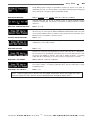
25
Assign MIDI program changes in bank #00 to activate any preset in any order as
specified by this map. Use the FX LEVEL to select MIDI number (program change) and
the FX VAL2 knob to assign any preset to that MIDI number.
MIDI PRESET MAPPING
Values: FX LEVEL: 1–127; FX VAL2: P00-P99
C00-C99
A00-A49
Outgoing MIDI data can be set to include (echo) or exclude (default) incoming
continuous controller data. This feature is useful when recording continuous controller
sequences.
MIDI CONT. CONTROLLER ECHO
Values: On
Off
Restores all rewritable presets (Player’s Lounge) to factory originals. WARNING: This
will erase all your custom presets EVEN IF MEMORY PROTECTION IS ON! Press TAP
once to initiate and press TAP a second time to verify the preset restore operation Press
EXIT before the second TAP to cancel the restore.
FACTORY PRESET RESTORE
Values: none
Transfers all Utility settings (every Utility menu parameter) to another Cyber–Twin SE™
or MIDI device. Press TAP to initiate.
MIDI DUMP UTILITIES
Values: none
Transfers any one preset (every parameter) to another Cyber–Twin SE™ or MIDI device.
The current preset is automatically selected, but you can use the data wheel to select
any preset (not audible) to transfer. Press TAP to initiate the dump. A receiving
Cyber–Twin SE™ will prompt you to select a Player’s Lounge preset to overwrite.
MIDI DUMP - ANY PRESET
Values: P00-P99
C00-C99
A00-A49
Transfers all presets (every parameter) to another Cyber–Twin SE™ or MIDI device.
Press TAP to initiate. A receiving Cyber–Twin SE™ will only load Player’s Lounge
(rewritable) presets.
MIDI DUMP - ALL PRESETS
Values: none
NOTE: Original Cyber–Twin™ presets may be loaded successfully into a new Cyber–Twin SE™.
However, Cyber–Twin SE™ presets are not compatible with the original Cyber–Twin™
w w w.f e n d e r.com
✧
w w w. m r g e a r h e a d .net
26
Appendices
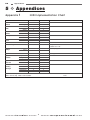
5 ✧ Appendices
Appendix
FUNCTION
Basic
Channel
Mode
Note
Number
Velocity
After
Touch
Pitch Bender
Control Change
Program
Change
System Exclusive
System
Common
System
Real Time
Auxiliary
Messages
Mode 1: Omni On, Poly
Mode 3: Omni Off, Poly
1
Default
Changed
Default
Messages
Altered
Note Number
True Voice
Note ON
Note OFF
Keys
Channel
MIDI Implementation Chart
TRANSMITTED
X
1-16
X
X
X
X
X
X
X
X
X
X
O
RECOGNIZED
1-16
1-16
Mode 2, Mode 4
Mode 2, Mode 4
X
X
X
X
X
X
X
X
O
O
O
O
X
X
X
X
X
X
X
X
X
X
O
X
X
X
X
X
X
X
X
X
X
Implemented
True #
Song Position
Song Select
Tune Request
Clock
Commands
Local On/Off
All Notes Off
Active Sensing
System Reset
GM ON
Mode 2: Omni On, Mono
Mode 4: Omni Off, Mono
w w w.f e n d e r.com
REMARKS
Memorized
Assignable Continuous Controller
numbers are 1–100
Internally mapped
See Appendix
O: Yes
X: No
✧
w w w. m r g e a r h e a d .net
Appendices
Appendix
2
27
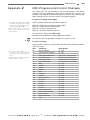
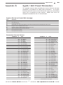
MIDI Program and Control Changes
The Cyber-Twin® SE will respond to and transmit program and control
changes when the appropriate MIDI receive and transmit channels are
selected. Use program and control changes to remotely select presets and
adjust settings either in real time or from a recorded sequence.
Program Change Messages
The Cyber–Twin SE™ uses the MIDI
convention of numbering which starts
with “0.” For example program change
6 activates preset 06 (not 06).
Bank change messages only need to
be sent once each time you change
bank numbers.
Select amplifier presets from the following banks:
Bank
Bank
Bank
Bank
00—MIDI Map (as defined in Utility Mode)
01—Fender Custom Shop presets
02—Player’s Lounge presets
03—Your Amp Collection presets
Use the format: Bn 00 00 32 bb Cn pp
(n=MIDI channel, bb=bank number, pp=preset number)
Activate the tuner using program change 127 in banks 01–03.
Control Change
Adjust amplifier settings using the following continuous controller numbers
and value ranges.
The Cyber–Twin SE™ uses a
continuous controller resolution of
0–127 (it will not accept 16,384 step
sizes).
Data increment/decrement models the
data wheel by +/– 1 steps.
CC#
07
32
85
86
96
97
102
103
104
105
106
107
108
109
110
111
112
113
114
115
116
117
118
119
Parameter
Master Volume
LSB for Bank Changes
Effects/Reverb Bypass
Hum Reduction
Data Increment2
Data Decrement2
Gain
Volume
Treble
Middle
Bass
Presence
Reverb
Master Volume
FX Level
FX Val 1
FX Val 2
FX Val 3
FX Val 4
Reverb In [Dwell]
Reverb Tone [Shape]
Reverb Time
Reverb Diffusion
Tap
w w w.f e n d e r.com
✧
Value Range
(0 - 127)
(0 - 127)
OFF=(0-63), ON=(64-127)
OFF=(0–63), ON=(64-127)
(Linked to the Data Wheel)
(Linked to the Data Wheel)
(0 - 127)
(0 - 127)
(0 - 127)
(0 - 127)
(0 - 127)
(0 - 127)
(0 - 127)
(0 - 127)
(0 - 127)
(0 - 127)
(0 - 127)
(0 - 127)
(0 - 127)
(0 - 127)
(0 - 127)
(0 - 127)
(0 - 127)
w w w. m r g e a r h e a d .net
28
Appendices
Appendix
3
SysEx ◊ MIDI Dump
This appendix contains tables describing the System Exclusive message
components and protocol for MIDI Dump. The SysEx device ID must be set
to Omni (or the same as the transmitting device ID) to accomplish the data
transfers. NOTE: Data values are displayed in hexadecimal with “H” for
clarification.
System Exclusive Header
VALUE
DESCRIPTION
F0H
08H
nnH
12H
ffH
F7H
Start of System Exclusive Message
Fender Manufacturer ID
nn = Device ID (minus one)
Amp ID number 12H. The upper nibble identifies the Cyber-Twin® SE amplifier and the lower nibble designates software version.
Function ID number (01H=Utilities message; 02H=One preset message; 03H=All presets message)
End of System Exclusive Message
System Exclusive Data Packet
VALUE
DESCRIPTION
F0H
08H
nnH
12H
ffH
PnH
Data
cbH
F7H
Start of System Exclusive Message
Fender Manufacturer ID
nn = Device ID (minus one)
Amp ID number 12H. The upper nibble identifies the Cyber-Twin® SE amplifier and the lower nibble designates software version
Function ID number (01H=Utilities message; 02H=One preset message; 03H=All presets message)
Packet Number
Data bytes: The data bytes have been formatted following the MIDI Specification
Checksum byte used for error checking
End of System Exclusive Message
System Exclusive End of File Message
VALUE
DESCRIPTION
F0H
08H
nnH
12H
ffH
7BH
F7H
Start of System Exclusive Message
Fender Manufacturer ID
nn = Device ID (minus one)
Amp ID number 12H. The upper nibble identifies the Cyber-Twin® SE amplifier and the lower nibble designates software version
Function ID number (01H=Utilities message; 02H=One preset message; 03H=All presets message)
End of System Exclusive File Byte
End of System Exclusive Message
MIDI Dump Initiation Message
VALUE
DESCRIPTION
F0H
08H
nnH
21H
04H
23H
00H
00H
00H
ddH
7BH
F7H
Start of System Exclusive Message
Fender Manufacturer ID
nn = Device ID (minus one)
Amp ID number 21H. The upper nibble identifies the Cyber-Twin® SE amplifier and the lower nibble designates software version.
Message ID number for additional parameter controls.
ID number indicating request for a MIDI Dump
Unused Data Byte
Unused Data Byte
Unused Data Byte
Dump ID byte: 01H = Transmit Utilities, 02H = Transmit One Preset, 03H = Transmit All Presets
End of System Exclusive File Byte
End of System Exclusive Message
w w w.f e n d e r.com
✧
w w w. m r g e a r h e a d .net
Appendices
Appendix
29
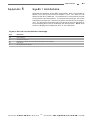
SysEx ◊ Edit Preset Parameters
4
This appendix contains tables describing the System Exclusive message
components and protocol for editing preset parameters. The System
Exclusive device ID must be set to Omni (or the same as the transmitting
device ID) to accomplish the data transfers. NOTE: Data values are
displayed in hexadecimal with “H” for clarification.
System Exclusive Preset Edit Message
VALUE
DESCRIPTION
F0H
08H
nnH
12H
05H
ddH
vvH
7BH
F7H
Start of System Exclusive Message
Fender Manufacturer ID
nn = Device ID (minus one)
Amp ID number 12H. The upper nibble identifies the Cyber-Twin® SE amplifier and the lower nibble designates software version.
Message ID number for additional parameter controls.
Parameter ID number for additional parameter controls (See table below).
Value for the parameter you wish to edit (See table below).
End of System Exclusive File Byte
End of System Exclusive Message
Parameter IDs and Values
PARAMETER
Tone Stack Type
Tone Stack Position
Drive Circuitry
Effects Type
ID
00H
00H
00H
00H
00H
00H
01H
01H
02H
02H
02H
02H
02H
02H
02H
02H
02H
02H
02H
02H
02H
02H
02H
02H
03H
03H
03H
03H
03H
03H
03H
VALUE
00H = Tweed
01H = Blackface
02H = British
03H = Modern
04H = Neo British
05H = Dyna-Touch
00H = Pre-Distortion
01H = Post-Distortion
00H = Blackface Tube1
01H = Blackface Tube2
02H = Blackface Tube3
03H = Tweed Tube1
04H = Tweed Tube2
05H = Tweed Tube3
06H = Hot Rod Tube1
07H = Hot Rod Tube2
08H = Hot Rod Tube3
09H = HMB Tube1
0AH = HMB Tube2
0BH = HMB Tube3
0CH = Dyna Touch 1
0DH = Dyna Touch 2
0EH = Dyna Touch 3
0FH = Extreme
00H = None
01H = Mono Delay
02H = Dotted 8/16 Delay
03H = One-E-Da Delay
04H = Ping Pong Delay
05H = Swing Tap Delay
06H = Tape Echo
w w w.f e n d e r.com
✧
PARAMETER
Effects Type (continued)
ID
VALUE
03H 07H = Stereo Tape Echo
03H 08H = Stereo Flam Delay
03H 09H = Ducking Delay
03H 0AH = Backwards Delay
03H 0BH = Tremolo
03H 0CH = Amp Tremolo
03H 0DH = Auto Pan
03H 0EH = Phaser
03H 0FH = Vibratone
03H 10H = Pedal Wah
03H 11H = Touch Wah
03H 12H = Sine Chorus
03H 13H = Triangle Chorus
03H 14H = Sine Flange
03H 15H = Triangle Flange
03H 16H = Delay+Chorus
03H 17H = Delay+Flange
03H 18H = Delay+Phaser
03H 19H = Auto Swell+Chorus
03H 1AH = Ultra-Clean+Chorus
03H 1BH = Pitch Shift
03H 1CH = Ring Mod+Delay
03H 1DH = Auto Pan Delay
03H 1EH = Fuzz
03H 1FH = Resolver
03H 20H = Pedal Pitcher
03H 21H = Overdrive
03H 22H = Alienator
03H 23H = Pedal Wah+Delay
03H 24H = Touch Wah+Delay
03H 25H = Fuzz+Pedal Wah
Continued on next page
w w w. m r g e a r h e a d .net
30
Appendices
Parameter IDs and Values PARAMETER
Effects Type (continued)
Reverb Type
Timbre
Speaker Phase
Compressor
ID
03H
03H
03H
03H
03H
04H
04H
04H
04H
04H
04H
04H
04H
04H
04H
04H
05H
05H
05H
05H
05H
05H
05H
05H
05H
06H
06H
06H
06H
07H
07H
07H
07H
07H
Continued from previous page
VALUE
26H = Fuzz+Touch Wah
27H = Fuzz+Delay
28H = Octave+Tape Echo
29H = Mid Boost+Tape Echo
2AH = Overdrive+Tape Echo
00H = Small Room
01H = Large Room
02H = Small Hall
03H = Large Hall
04H = Arena
05H = Small Plate
06H = Large Plate
07H = Blackface Reverb
08H = Gated Reverb
09H = Small Ambience
0AH = Fender Reverb
00H = None
01H = Full Body
02H = Razor Edge
03H = Bright & Light
04H = Bass Booster
05H = Drop Scoop
06H = Super Bright
07H = Squawk
08H = Acoustic Scoop
00H = Standard Polarity
01H = Reverse Polarity
02H = Left Rev Polarity
03H = Right Rev Polarity
00H = OFF
01H = Low
02H = Medium
03H = High
04H = Even Higher
w w w.f e n d e r.com
✧
PARAMETER
Noise Gate Depth
Noise Gate Threshold
Expression Pedal Assignment
Continuous Controller Assignment
Effects/Reverb Bypass
ID
08H
09H
09H
09H
0AH
0AH
0AH
0AH
0AH
0AH
0AH
0AH
0AH
0AH
0AH
0AH
0AH
0AH
0AH
0AH
0AH
0BH
0CH
0CH
0CH
0CH
0CH
0CH
0CH
0CH
0CH
VALUE
0 – 127 (00H-7FH)
00H = Low
01H = Medium
02H = High
00H = Volume
01H = Gain
02H = Treble
03H = Middle
04H = Bass
05H = Presence
06H = Reverb
07H = Effects Level
08H = Effects Val 1
09H = Effects Val 2
0AH = Effects Val 3
0BH = Effects Val 4
0CH = Master Volume
0DH = Reverb Input
0EH = Reverb Tone
0FH = Reverb Time
10H = Reverb Diffusion
Same As Expression Pedal
00H = FX Input
01H = Reverb Input
02H = FX Output
03H = Reverb Output
04H = FX & Reverb Input
05H = FX In & Reverb Out
06H = FX Out & Reverb In
07H = FX & Reverb Out
08H = Vibro Fast/Slow
w w w. m r g e a r h e a d .net
Appendices
Appendix
5
31
SysEx ◊ Handshake
Following the guidelines of the MIDI specifications, data is transmitted as
follows: First, the System Exclusive Header is sent. The amp will wait
200ms to look for a handshake. If no handshake is received then the amp
will transmit the first data packet. The transmission continues until all the
information has been sent. After the last packet, the End of File message is
sent. The System Exclusive device ID must be set to Omni (or the same as
the transmitting device ID) to accomplish the data transfers. NOTE: Data
values are displayed in hexadecimal with “H” for clarification.
System Exclusive Handshake Message
VALUE
DESCRIPTION
F0H
7EH
nnH
hdH
ppH
F7H
Start of System Exclusive Message
Universal Message
nn = Device ID (minus one)
Handshake ID (7CH=Wait; 7DH=Cancel; 7EH=Not Acknowledge; 7FH=Acknowledge)
Packet Number
End of System Exclusive Message
w w w.f e n d e r.com
✧
w w w. m r g e a r h e a d .net
32
Appendices
Appendix
6
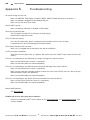
Troubleshooting
No sound coming from the unit...
Make sure MASTER, TRIM, GAIN, VOLUME, TREBLE, MIDDLE, BASS and guitar are all above “1.”
Make sure nothing is plugged into the HEADPHONE jack.
Make sure you are not in Tuner mode.
Cannot SAVE a preset...
Make sure Memory Protection is disabled in Utility Mode.
Clean tone sounds distorted...
Turn Trim down if the red LED is constantly on while playing.
Reduce effects loop device levels.
The 3 FX knobs do nothing...
Press the FX button and if “None” is displayed, rotate the data wheel to select an effect.
If connected, press the FX/Reverb Bypass footswitch button.
The 4-Button footswitch does not work...
Make sure it is plugged into the footswitch jack and not a MIDI jack.
An Error message is displayed...
Write down the message exactly as it appears and contact your local Fender® repair center with this information.
The unit is not responding to any MIDI program change messages from external devices...
Make sure the MIDI Receive channel is set properly.
Make sure the MIDI Cables are connected properly.
The unit is not responding to any MIDI Continuous Controller Messages from external devices...
Make sure the MIDI Receive channel is set properly.
Make sure the continuous controller numbers matches the value in the UTILITY menu or is one of the predefined numbers listed in the appendices.
Make sure the MIDI Cables are connected properly.
The unit is not responding to any System Exclusive Information from external devices...
Make sure the System Exclusive Device ID is set properly.
Make sure the MIDI Cables are connected properly.
General MIDI questions...
Visit www.midi.org
Problem still persists after trying these solutions...
Consult an authorized Fender® Service Center or visit www.fender.com or www.mrgearhead.net and
click on support.
w w w.f e n d e r.com
✧
w w w. m r g e a r h e a d .net
Appendices
Appendix
7
Specifications
TYPE:
PR 393
PART NUMBERS:
2290000010 (120V, 60Hz) USA
2290003010 (240V, 50Hz) AUS
2290005010 (230V, 50Hz) EUR
POWER REQUIREMENTS:
360W
POWER OUTPUT:
65W per channel (130W total) @ 5% THD
RATED LOAD IMPEDANCE:
8 ohms per channel
SENSITIVITY:
adjustable using TRIM control
PREAMP INPUT IMPEDANCE:
900k ohm
EFFECTS LOOP
(mono send, stereo return)
-10dBv / +4dBu switchable
220 ohm, impedance balanced
20k ohm minimum, balanced
NOMINAL LEVEL:
OUTPUT IMPEDANCE:
INPUT IMPEDANCE:
SPDIF LINE OUT JACK:
RCA jack, digital stereo
XLR OUTPUT JACKS
(stereo / mono switchable)
0dBv
300 ohm, impedance balanced
NOMINAL LEVEL:
OUTPUT IMPEDANCE:
2290001010 (110V, 60Hz) TW
2290004010 (230V, 50Hz) UK
2290007010 (100V, 50/60Hz) JPN
TUBE COMPLEMENT:
Groove Tubes, two (2) x 12AX7WC
SPEAKER COMPLEMENT:
Celestion, Two (2) x G12T-100 (12-inch, 8 ohm)
FUSES
FOOTSWITCH
PRIMARY:
SECONDARY:
FOUR BUTTON:
ONE BUTTON:
F4A 125V for 100V and 120V units, F2A 250V for 230V and 240V units
digital supply: F2A
analog supply: Two (2) x T1A
Quick-access key recall functions, 5-pin DIN (MIDI-type) cord
Reverb/Effects Bypass and Vibratone rotor speed select
standard one-button toggle type P/N 099-4055-000 or 00-57172-000
EXPRESSION PEDAL JACK:
1/4-inch (Tip, Sleeve) analog, compatible with any passive
volume pedal, 10k to 250k ohm, (ideal audio taper is 20k 25%)
REVERB/FX BYPASS JACK:
1/4-inch for connection to the included one-button footswitch
MIDI JACKS:
IN, OUT, THRU
HEADPHONES JACK:
1/4-inch stereo
DIMENSIONS
WEIGHT:
33
HEIGHT:
WIDTH:
DEPTH:
18 9/32 in
26 1/8 in
12 1/8 in
(46.4 cm)
(66.4 cm)
(30.8 cm)
55 lb
(25 kg)
Product specifications are subject to change without notice.
w w w.f e n d e r.com
✧
w w w. m r g e a r h e a d .net
Notes
w w w.f e n d e r.com
✧
w w w. m r g e a r h e a d .net
Notes
w w w.f e n d e r.com
✧
w w w. m r g e a r h e a d .net
P/N 064391
REV A