1
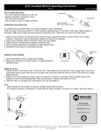
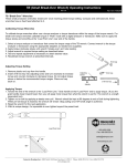
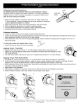
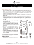
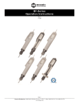
0
1
0
1
TITAN
100i
250i
75F
150F
300F
600F
US
6 - 12
ES
13 - 20
Service
Calibration
Repairs
SERVICE-HOTLINE
408-292-2214
MANUFACTURER’S
DECLARATION
Our torque wrenches meet the
requirements of ISO Standards
6789, Type II: Signal Torque
Wrenches; Class A: Wrench
with adjustable scale.
a
b
0
1
c
d
0
1
e
TITAN 600F
f
4
1
2
100%
0
1
0
1
3
4
100%
0
1
0
1
6
5
1
3
2
180
7
9
8
10
11
5
+10%
TITAN
These operating instructions contain important
information for the
smooth operation of
your torque wrench!
Do not use your torque
wrench as a striking tool
as it might be destroyed
in the process.
Before using your
torque wrench please
ensure that it is calibrated
according to specifications. A test certificate in
compliance with ISO 6789
is enclosed with all new
torque wrench models.
CONTENTS
Manufacturer’s
declaration . . . . . . . . . . . 3
Safety instructions . . . . . 6
Range of application . . . 7
Please attach only standard sockets and accessories to your torque
wrench. Do not use worn
or defective accessories
and, if at all possible, do
not use reduction
adapters.
Functional units . . . . . . . 7
Setting the torque. . . . . . . 7
Controlled tightening
of screw. . . . . . . . . . . . . . 8
Divisions . . . . . . . . . . . . . 9
Testing & servicing. . . . . 9
Conservation. . . . . . . . . 10
In order to avoid the
danger of slipping always
attach your torque wrench
onto the bolted joint at a
right angle.
Accessories &
spare parts . . . . . . . . . . 10
Measures & units . . . . . 10
Measurements &
Weights . . . . . . . . . . . . . 10
Please do not exceed the
set torque value. Your
torque wrench automatically triggers when set
torque is reached. A click
signal is heard and felt.
After this relieve strain as
quickly as possible.
Warranty . . . . . . . . . . . . 11
Torque conversion
factors . . . . . . . . . . . . . . 12
SAFETY INSTRUCTIONS
Your torque wrench
must not be used to loosen
bolted joints.
Your torque wrench is a
precision tool. Despite its
robust design the torque
wrench should be used
like measuring and test
equipment.
Please do not exceed the
permitted range of torque
on your torque wrench.
Excessive tightening might
cause material rupture in
your torque wrench!
6
TITAN
RANGE OF
APPLICATION
SETTING THE TORQUE
Pictures 1 – 4
Your torque wrench
is only suitable for the
specified purpose.
1
Pull out the locking
button on the end of the
handle.
Your torque wrench is
designed exclusively for
the controlled tightening
of bolts.
2
Turn the handle in a
clockwise or anticlockwise
direction to set the torque.
Set the torque value to
5-10 % above the desired
value.
Any other additional
use of your torque wrench
is considered an abuse of
the specified purpose.
The company does not
accept liability for damage incurred in this way,
nor will it, in this case,
accept any other claims
under the guarantee.
The set torque is readable on the scale or on
the scale connected to
the graduated collar*.
According to the
model, the scale or
graduated collar*
shows different pitches. A table with the
respective divisions
can be found in the
section “DIVISIONS”.
FUNCTIONAL UNITS
a Ratchet drive with
push-through, or interchangeable square
b Intermediate lever
3
Now set the torque
value, previously set 5-10%
above the desired value,
back to the true value.
c Spring
d Scale + graduated collar
lbf•in / lbf•ft and N•m
e Handle
Please pay attention to
the unit of measurement on the scale
applicable to you
(lbf•in / lbf•ft or N•m).
f Locking button
4
Push the locking
button back into the cavity.
*According to the model!
7
TITAN
CONTROLLED
TIGHTENING OF SCREW
the extension that
takes the torque
wrench as closely as
possible to the thread
joint.
Pictures 5 – 11
Your torque wrench is
suitable for controlled
right hand tightening and
left-handed-way.
10
Operate your torque
wrench exclusively by the
handle using 1 or 2 hands,
at the same time pulling in
the direction of the arrow
until it releases (click signal). At this point the set
torque will have been
achieved.
The tightening direction is indicated by
an arrow on the
measuring tool.
According to your
model, the direction
is reversed as follows:
5
TITAN 100i-300F with
interchangeable square.
Take out the square on
the mushroom head, turn
the torque wrench and
replace the square.
The releasing signal is
clearly heard and felt.
Do not keep on tightening the bolt after
the releasing signal!
After the automatic
release your torque
wrench is immediately
ready for further action.
6
TITAN 600F with
push-through square.
Push the square through
the ratchet.
Attention!
The torque transmission is dependent on
the lever arm. The use
of the tool outside the
handle area, or the
use of extension tubes
or special additional
tools, has a negative
effect on the torque
values. Always apply
the force on the centre of the handle, do
not use extensions.
7
Attach possible accessories and/or matching
socket for your screw
connection.
8
Place your torque
wrench together with the
socket onto the thread
joint at a right angle.
9
Attention!
To avoid damage or
slipping always use
8
TITAN
DIVISIONS
TORQUE WRENCH
Graduation
Graduation - collar
5 lbf•in
10 lbf•in
2.5 lbf•ft
5 lbf•ft
10 lbf•ft
10 lbf•ft
no collar
1 lbf•in
0.25 lbf•ft
0.5 lbf•ft
1 lbf•ft
1 lbf•ft
# !
TITAN
100i
250i
75F
150F
300F
600F
1/4“
3/8“
3/8“
1/2“
1/2“
3/4“
20-100 lbf•in
50-250 lbf•in
10-75 lbf•ft
30-150 lbf•ft
60-300 lbf•ft
120-600 lbf•ft
TESTING & SERVICING
For calibration, readjustment or repairs
we recommend the
service department
of Mountz Inc., the
in-house calibration
lab.
The manufacturer guarantees a torque wrench
accuracy of +/- 4% to the
scale value in question at a
stress cycle of max. 5000.
It is therefore necessary
that you test your torque
wrench at least every 5000
stress cycles on a traceable
calibrated testing device.
Before a longer period
of non-utilisation the
compression spring of
your torque wrench needs
to be released. Turn the
torque back to the smallest value on the scale.
Protect your torque
wrench from dust, dirt and
sand by placing it back in
the box after use and store
it in a dry, clean place.
For the testing of your
tool we recommend
torque analyzer
testing equipment.
For information
contact Mountz Inc.
or simply call our
Service-Hotline.
Clean your torque
wrench on the outside
with a dry, clean cloth.
Do not use cleaning spirit
or any other chemical
solvents as these interfere
with the permanent lubrication of the mechanism.
Your torque wrench has
to be calibrated at least
once a year. Re-adjustments should only be
carried out either by authorised personnel, accredited
calibration labs or the
manufacturer.
9
TITAN
sories or spare parts for
your torque wrench are
listed on the Mountz website www.etorque.com.
CONSERVATION
Packaging materials as
well as the torque wrench
are made of recyclable
materials and are to be
disposed of at the appropriate recycling centers.
When placing a spare
part order always
state the serial number and year or manufacture of your torque
wrench model. (For
details refer to test
certificate).
ACCESSORIES &
SPARE PARTS
11
Extensions, sockets
screwdriver, screwdriver
bits, rotation angle measuring equipment and
special tools for a variety
of applications.
MEASURES & UNITS
For details about measures, torque, conversion
tables and stud torque
units please refer to
manufacturer’s catalogue.
Use only original accessories and spare parts.
Information about the
range of available acces-
MEASUREMENTS & WEIGHTS
Measurements in mm
TITAN
# !
100i
250i
75F
150F
300F
600F
1/4“
3/8“
3/8“
1/2“
1/2“
3/4“
20-100 lbf•in
50-250 lbf•in
10-75 lbf•ft
30-150 lbf•ft
60-300 lbf•ft
120-600 lbf•ft
a
b
c
33
33
33
33
33
33
43
43
43
43
46
69
307.0
350.0
394.0
485.0
664.5
1,200.0
TITAN 100i - 300F
TITAN 600F
10
Weights in kg
0.5
0.6
0.9
1.1
1.6
5.2
TITAN
WARRANTY
Every Mountz tool is
thoroughly checked and
tested before shipment.
Should defects due to
faulty materials and/or
workmanship develop
within one (1) year from
the date of sale, the tool
will be repaired and put in
workable condition or
replaced free of charge (at
Mountz option), if returned
to Mountz, Inc.
This warranty is not
valid if a product has been
misused, tampered or
abused. Also, Mountz warranty does not cover rental
or leased products. Any
questions concerning warranty should be directed to
Mountz Customer Service.
11
12
980.7
9.807
0.01
0.706
9.807
0.098
0.0001
1.356
0.113
0.007
1
0.01
0.001
= N•m
1389
13.89
0.014
192
16
1
141.6
1.416
0.142
= ozf•in
Example: Convert 5 lbf•ft into cN•m
Solution: 5 x 135.6 = 678 cN•m
86.8
0.868
0.0009
12
1
0.0625
8.851
0.088
0.009
= lbf•in
7.233
0.072
0.00007
1
0.083
0.005
0.738
0.007
0.0007
= lbf•ft
Corresponding unit
Units to be converted x Factor = Corresponding unit
9807
1 kgf•m (kp•m)
Conversion-formula:
98.07
1 kgf•cm (kp•cm)
135.6
1356
0.098
1 lbf•ft
113
1 lbf•in
1 gf•cm
11.3
7.062
1 ozf•in
1
100
10
1000
1 N•m
0.1
= cN•m
1 cN•m
1
= mN•m
1 mN•m
Units to be converted
TORQUE CONVERSION FACTORS
100000
1000
1
13826
1152.1
72
10197
102
10.2
= gf•cm
100
1
0.001
13.83
1.152
0.072
10.2
0.102
0.01
1
0.01
0.00001
0.138
0.0115
0.0007
0.102
0.001
0.0001
= kgf•cm (kp•cm) = kgf•m (kp•m)
TITAN
TITAN
Servicio
Calibración
Reparaciones
SERVICIO HOTLINE
408-292-2214
DECLARACION DEL
FABRICANTE
Nuestras llaves dinamométricas
cumplen con los requerimientos de
las Normas ISO 6789, tipo II: Llaves
Dinamométricas de señal. Clase A:
Llave con escala ajustable.
13
TITAN
Estas instrucciones de uso
contienen información
importante para el correcto funcionamiento de llave
dinamométrica!
No use su llave dinamométrica como una herramienta de golpe, ya que
podría destruirla.
Antes de usar su llave
dinamométrica, por favor,
asegúrese de que está
calibrada de acuerdo a las
especificaciones. Se suministra un certificado de
verificación de acuerdo a
las normas ISO 6789 con
todos los modelos de
llave dinamométrica.
CONTENIDO
Declaración del
fabricante . . . . . . . . . . . 13
Instrucciones de
seguridad . . . . . . . . . . . 14
Rango de aplicación. . . 15
Unidades funcionales . 15
Por favor, use únicamente vasos y accesorios
estandar con su llave
dinamométrica. No use
accesorios defectuosos o
incorrectos, y en todo lo
posible no use adaptadores reductores.
Ajustar el par . . . . . . . . 15
Apriete controlado
de un tornillo . . . . . . . . 16
Divisiones . . . . . . . . . . . 17
Comprobación
y servicio . . . . . . . . . . . 17
Conservación . . . . . . . . 18
A fin de evitar el peligro
de deslizamientos coloque
siempre su llave dinamométrica sobre la junta a
apretar en ángulo recto.
Accesorios y repuestos 18
Medidas y unidades . . . 18
Medidas y pesos . . . . . 19
Garantía. . . . . . . . . . . . . 19
Factores de conversión
de par . . . . . . . . . . . . . . 20
Por favor, no exceda el
par fijado. Su llave dinamométrica se dispara automáticamente una vez
alcanzado el par fijado.
Se oye y siente una clara
señal. Deje de hacer fuerza inmediatamente después de oír la señal.
INSTRUCCIONES DE
SEGURIDAD
Por favor, no sobrepase
el rango de su llave dinamométrica. Una sobrecarga puede dar lugar a la
rotura de algún componente de su llave dinamométrica!
Su llave dinamométrica
es una herramienta de
precisión. A pesar de su
robusto diseño, la llave
dinamométrica ha de
usarse como un equipo de
medida y comprobación.
14
TITAN
AJUSTAR EL PAR
No debe usar su llave
dinamométrica para soltar
tornillos.
Dibujos 1 – 4
1
Extraiga el botón de
enclavamiento del extremo del mango.
RANGO DE APLICACIÓN
Su llave dinamométrica
es válida para su uso
específico.
2
Gire el mango en el
sentido de las agujas del
reloj o en sentido contrario
para ajustar el par. Ajuste
el par de giro 5-10% por
encima del valor deseado.
Su llave dinamométrica
está diseñada exclusivamente para realizar el
apriete controlado de
tornillos o tuercas.
El par ajustado se
puede leer en la escala
o en la escala unida al
anillo de escalas.
Según el modelo, la
escala o el anillo de
escalas presentan divisiones diferentes. En el
capítulo "Divisiones"
se ofrece una tabla con
las divisiones respectivas.
Cualquier otro uso de
su llave dinamométrica
será considerado como
abuso de utilización.
El fabricante no acepta
ninguna responsabilidad
por los daños ocasionados en estos casos, ni
aceptará por tanto ninguna otra reclamación en
garantía.
3
Vuelva a ajustar ahora
el par realmente deseado,
que antes se había puesto
muy alto (5-10%).
UNIDADES
FUNCIONALES
a Accionamiento de
carraca con cuadradillo
de pasante y de transposición
b Palanca intermedia
c Muelle
d Escala + anillo de
escalas
lbf•in / lbf•ft y N•m
e Mango
f Botón de enclavamiento
Por favor, ponga atención a las unidades de
medida que corresponda en su caso
(lbf•in / lbf•ft o N•m).
4
Vuelva a introducir el
botón de enclavamiento
en el enganche.
*Según modelo!
15
TITAN
APRIETE CONTROLADO
DE UN TORNILLO
9
¡Atención!
Para evitar balanceos
o deslizamientos
coloque siempre tan
cerca como sea posible su llave dinamométrica de la cabeza
de la unión roscada.
Dibujos 5 – 11
Su llave dinamométrica
es apropiada para el
apriete controlado a la
derecha y paso a la
izquierda.
10
Accione su llave dinamométrica agarrando ésta
exclusivamente por el
mango con una o las dos
manos y girando de modo
homogéneo en el sentido
de la flecha, hasta que
salte (clic). En este punto
ya ha alcanzado el par
deseado.
El sentido de giro
de apriete se indica
mediante una flecha
en la herramienta de
medición. El cambio
del sentido de giro
se realiza, según el
modelo, como sigue:
5
TITAN 100i-300F con
cuadradillo de transposición.
Extraer el cuadradillo
de la campana, girar la
llave y volver a colocar
el cuadradillo.
La señal de salto se
oye y se siente con
claridad. No prosiga
apretando el tornillo
una vez se haya
producido el salto.
6
TITAN 600F con
cuadradillo de pasante.
Presionar el cuadradillo a
través de la carraca.
Tras el salto, llave dinamométrica está de nuevo
preparada para ser utilizada.
7
Encaje los accesorios
posibles y/o la pieza adecuada de llave de vaso
para su atornilladura.
8
Ponga su llave dinamométrica con el vaso
sobre la cabeza del
tornillo en ángulo recto.
16
08_Titan_ES
11.11.2002
16:46 Uhr
Seite 17
TITAN
herramientas modulares especiales, los valores de par quedarán
limitados. Aplique la
fuerza siempre en el
centro del mango y no
utilice ningún empalme.
¡Atención!
La transmisión del par
depende del brazo de
palanca. Si se acciona
la llave por otro sitio
distinto del mango, o
si se utilizan tubos de
alargamiento o
DIVISIONES
LLAVE DINAMOMÉTRICA
División - escala División – anillo de escalas
# !
TITAN
100i
250i
75F
150F
300F
600F
1/4“
3/8“
3/8“
1/2“
1/2“
3/4“
20-100 lbf•in
50-250 lbf•in
10-75 lbf•ft
30-150 lbf•ft
60-300 lbf•ft
120-600 lbf•ft
5 lbf•in
10 lbf•in
2.5 lbf•ft
5 lbf•ft
10 lbf•ft
10 lbf•ft
no collar
1 lbf•in
0.25 lbf•ft
0.5 lbf•ft
1 lbf•ft
1 lbf•ft
Para mas información
escriba a Mountz Inc.
o llame a nuestro
Servicio-Hotline.
COMPROBACIÓN Y
SERVICIO
Su llave dinamométrica
debe ser calibrada al
menos una vez al año.
Estos reajustes deben ser
realizados por personal
autorizado, laboratorios de
calibración acreditados o
por el fabricante.
El fabricante garantiza en
sus llave dinamométrica
una precisión del +/-4% del
valor fijado en la escala
durante aproximadamente
5000 ciclos (máximo) de
apriete. Por esta razón, es
necesario comprobar su
llave dinamométrica al
menos cada 5000 ciclos en
un equipo de calibración
con trazabilidad.
Para la recalibración,
reajuste o reparaciones le recomendamos
el servicio de Mountz
Inc. y su laboratorio
acreditado.
Para la comprobación
de su herramienta
nosotros le recomendamos el equipo de
comprobación analizador de par.
17
TITAN
giro, así como herramientas especiales para una
amplia gama de aplicaciones.
Cuando se espere un
largo periodo de reposo
de la herramienta, es
aconsejable aflojar el
muelle de su llave dinamométrica. Fije la llave
dinamométrica al mínimo
de la escala.
Use únicamente accesorios y repuestos originales.
Proteja su llave dinamométrica del polvo,
suciedad y arena, guardándola en su caja después del uso y almacenándola en un lugar limpio y
seco.
En la página web de
Mountz ww.etorque.com
se ofrece una lista con
información acerca de la
gama de accesorios
disponibles o repuestos
para su llave dinamométrica.
Limpie su llave dinamométrica exteriormente
con un trapo seco y
limpio. No use alcoholes
o cualquier otro disolvente químico, ya que esto
perjudica la permanente
lubricación del mecanismo.
Al pasar un pedido
indique el número
de serie y año de
fabricación de su
llave dinamométrica.
(Para mas detalles,
vea el certificado de
comprobación).
CONSERVACIÓN
MEDIDAS Y UNIDADES
Los materiales de
embalaje así como su
llave dinamométrica son
materiales reciclables, por
lo que deben ser puestos
a disposición del apropiado centro de reciclaje.
Para mas detalles acerca de medidas, pares,
tablas de conversión
y unidades de fuerza
diríjase al catálogo del
fabricante.
ACCESORIOS Y
REPUESTOS
11
Prolongaciones, piezas
de llave de vaso, puntas
recambiables de destornillador, aparatos de
medición del ángulo de
18
08_Titan_ES
11.11.2002
16:48 Uhr
Seite 19
TITAN
MEDIDAS Y PESOS
Medidas en mm
TITAN
# !
100i
250i
75F
150F
300F
600F
3/8“
3/8“
1/2“
1/2“
1/2“
3/4“
20-100 lbf•in
50-250 lbf•in
10-75 lb•ft
30-150 lbf•ft
60-300 lbf•ft
120-600 lbf•ft
Pesos en kg
a
b
c
33
33
33
33
33
33
43
43
43
43
46
69
307.0
350.0
394.0
485.0
664.5
1,200.0
TITAN 100i - 300F
0.5
0.6
0.9
1.1
1.6
5.2
TITAN 600F
GARANTÍA
Esta garantía no será
válida si el producto se ha
usado incorrectamente, se
ha forzado o se han excedido los límites de uso
debido. Asimismo, la
garantía de Mountz no
cubre productos alquilados. Las consultas relativas a la garantía deben
dirigirse al servicio de
atención al cliente de
Mountz.
Todas las herramientas
de Mountz son inspeccionadas a fondo y
probadas antes del envío.
Si en un plazo de un (1)
año a partir de la fecha de
venta aparecieran fallos
debidos a materiales y/o
trabajos defectuosos, la
herramienta en cuestión
se reparará y se pondrá en
condiciones de uso o se
remplazará por otra nueva
de modo gratuito (a discreción de Mountz) si se
devuelve a Mountz, Inc.
19
100
1000
7.062
1 N•m
1 ozf•in
20
98.07
9807
1 gf•cm
1 kgf•cm (kp•cm)
1 kgf•m (kp•m)
980.7
9.807
0.098
0.0001
1.356
0.113
0.007
1
0.01
0.001
= N•m
1389
13.89
0.014
192
16
1
141.6
1.416
0.142
= ozf•in
Solution: 5 x 135,6 = 678 cN•m
86.8
0.868
0.0009
12
1
0.0625
8.851
0.088
0.009
= lbf•in
7.233
0.072
0.00007
1
0.083
0.005
0.738
0.007
0.0007
= lbf•ft
Corresponding unit
Units to be converted x Factor = Corresponding unit
Example: Convert 5 lbf•ft into cN•m
Conversion-formula:
0.01
0.098
1 lbf•ft
9.807
135.6
113
1356
1 lbf•in
11.3
0.706
1
0.1
1
10
= cN•m
1 cN•m
= mN•m
1 mN•m
Units to be converted
FACTORES DE CONVERSIÓNDE PAR
100000
1000
1
13826
1152.1
72
10197
102
10.2
= gf•cm
100
1
0.001
13.83
1.152
0.072
10.2
0.102
0.01
1
0.01
0.00001
0.138
0.0115
0.0007
0.102
0.001
0.0001
= kgf•cm (kp•cm) = kgf•m (kp•m)
TITAN
Mountz Inc.
1080 N. 11th St. ● San Jose, CA 95112
Phone: 408-292-2214
Fax: 408-292-2733
Internet: www.etorque.com
e-mail: [email protected]