1
ART56504.book Page 4 Mardi, 6. juillet 2004 1:58 13
LV power circuit breakers
and switch-disconnectors
Masterpact NT and NW
Catalogue
2004
ART56504.book Page 2 Mardi, 6. juillet 2004 1:58 13
0
The Guiding System, the new way to create your
electrical installations
A comprehensive offer of products with consistent design
The Guiding System is first and foremost a Merlin Gerin product
offer covering all electrical distribution needs. However, what
makes all the difference is that these products have been designed
to operate togheter: mechanical and electrical compatibility,
interoperability, modularity, communication.
Thus the electrical installation is both optimised and more efficient:
better continuity of supply, enhanced safety for people and
equipment, guaranteed upgradeability, effective monitoring and
control.
Tools to simplify design and implementation
With the Guiding System, you have a comprehensive range of tools
- the Guiding Tools - that will help you increase your product
knowledge and product utilisation. Of course this is in compliance
with current standards and procedures.
These tools include technical booklets and guides, design aid
software, training courses, etc. and are regularly updated.
For a genuine partnership with you
Because each electrical installation is unique, there is no standard
solution. With the Guiding System, the variety of combinations
allows for genuine customisation solutions. You can create and
implement electrical installations to meet your creative
requirements and design knowledge.
You and Merlin Gerin’s Guiding System form a genuine partnership.
For more details on the Guiding System,
consult www.merlin-gerin.com
ART56504.book Page 3 Mardi, 6. juillet 2004 1:58 13
0
A consistent design of offers from
Medium Voltage to Ultra terminal
All Merlin Gerin offers are designed according to
electrical, mechanical and communication consistency
rules.
The products express this consistency by their overall
design and shared ergonomics.
Electrical consistency:
Discrimination guarantees
co-ordination between the
operating characteristics of
serial-connected circuitbreakers. Should a fault
occurs downstream, only the
circuit-breaker placed
immediately upstream from
the fault will trip.
The temperature rise tests
performed in the laboratory
guarantee safety and
durability of installations.
Each product complies with or enhances system performance at coordination level: breaking capacity, Isc, temperature rise, etc. for
more safety, continuity of supply (discrimination) or economic
optimisation (cascading).
The leading edge technologies employed in Merlin Gerin’s
Guiding System ensure high performance levels in discrimination
and cascading of protection devices, electrodynamic withstand of
switches and current distributors, heat loss of devices, distribution
blocks and enclosures.
Likewise, inter-product ElectroMagnetic Compatibilty (EMC) is
guaranteed.
Mechanical consistency:
Each product adopts dimensional standards simplifying and
optimising its use within the system.
It shares the same accessories and auxiliaries and complies with
global ergonomic choices (utilisation mode, operating mode, setting
and configuration devices, tools, etc.) making its installation and
operation within the system a simpler process.
Prefabricated and tested
solutions, upstream and
downstream from the device
complying with the
IEC 60439-1 switchboard
standard.
Direct connection of the
Canalis KT busbar trunking
on the Masterpact 3200 A
circuit-breaker.
Communication consistency:
Each product complies with global choices in terms of
communication protocols (Modbus, Ethernet, etc.) for simplified
integration in the management, supervision and monitoring
systems.
Thanks to the use of standard Web technologies, you can offer
your customers intelligent Merlin Gerin switchboards allowing
easy access to information: follow-up of currents, voltages,
powers, consumption history, etc.
Guiding Tools
for more efficient design
and implementation
of your installations.
Guiding Tools allow optimised use
of the Guiding System offers. They simplify life and
increase productivity.
1
ART56504.book Page 4 Mardi, 6. juillet 2004 1:58 13
0
SM6
Satia
Masterpact
Medium voltage switchboard
system from 1 to 36 kV
Ultra compact ML/LV substation
from 250 to 630 kVA
Protection switchgear
from 100 to 6300 A
Trihal
MV/LV dry cast resin
transformer
from 160 to 5000 kVA
Evolis
MV vacuum
switchgear and
components
from 1 to 24 kV.
The Technical guide
CAD software and tools
These technical guides help you comply with
installation standards and rules i.e.:
The electrical installation guide, the
protection guide, the switchboard
implementation guide, the technical booklets
and the co-ordination tables all form genuine
reference tools for the design of highperformance electrical installations.
For example, the LV protection co-ordination
guide - discrimination and cascading optimises choice of protection and
connection devices while also increasing
markedly continuity of supply in the
installations.
The CAD software and tools enhance
productivity and safety.
They help you create your installations
by simplifying product choice through
easy browsing in the Guiding System
offers.
Last but not least, they optimise
use of our products while also complying
with standards and proper procedures.
2
ART56504.book Page 5 Mardi, 6. juillet 2004 1:58 13
0
Compact
Multi 9
Prisma Plus
Protection switchgear system
from 100 to 630 A
Modular protection switchgear
system up to 125 A
Functional system for electrical
distribution switchboards
up to 3200 A
Pragma
Enclosures for
distribution
switchboards
up to 160 A
Canalis
Prefabricated Busbar
Trunking
from 25 to 4000 A
PowerLogic
Power
management
Training
Training allows you to acquire the Merlin
Gerin expertise (installation design, work
with power on, etc.) for increased efficiency
and a guarantee of improved customer
service.
The training catalogue includes beginner’s
courses in electrical distribution, knowledge
of MV and LV switchgear, operation and
maintenance of installations, design of LV
installations to give but a few examples.
3
PB100744-75
ART56504.book Page 6 Mardi, 6. juillet 2004 1:58 13
The original Masterpact has set a new standard for power
circuit breakers around the world.
Over the years, other major manufacturers have tried to keep up
by developing products incorporating Masterpact’s most innovative
features, including the breaking principle, modular design
and the use of composite materials.
Today, Schneider Electric continues to innovate
with the new Merlin Gerin Masterpact NT and NW ranges.
In addition to the traditional features of power circuit breakers
(withdrawability, discrimination and low maintenance), Masterpact
now offers built-in communications and metering functions,
all in optimised frame sizes.
Masterpact NT and NW incorporate the latest technology to
enhance both performance and safety. Easy to install, with
user-friendly, intuitive operation and environment-friendly design,
they are, quite simply, circuit breakers of their time.
4
Masterpact
General content
0
Presentation
6
Functions and characteristics
13
Dimensions and connection
59
Electrical diagrams
87
Installation recommendations
97
Additional characteristics
121
Catalogue numbers, spare parts
and order form
127
5
Presentation
New Masterpact,
new levels of performance
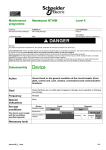
N1 - for standard applications with low short-circuit levels.
H1 - for industrial sites with high short-circuit levels or installations with two
parallel-connected transformers.
H2 - high-performance for heavy industry where very high short-circuits can
occur.
H3 - for incoming devices supplying critical applications requiring both high
performance and a high level of discrimination.
L1 - for high current-limiting capability and a
discrimination level (37 kA) as yet unequalled by
any other circuit breaker of its type; intended for
the protection of cable-type feeders or to raise
the performance level of a switchboard when
the transformer power rating is increased.
PB100722-24
PB100723-27
Five performance levels
PB100735-68
Integration in a communications network
Masterpact can be integrated in a general supervision system to optimise
installation operation and maintenance. The communication architecture is
open, and may be upgraded for interfacing with any protocol.
Switch-disconnector versions
The switch-disconnectors are derived directly from the circuit breakers
and offer the same features and performance levels. They are available in
HA, NA and HF versions, depending on the models. The HF version
includes instantaneous protection to prevent closing on a short-circuit.
Once closed, the switch-disconnectors are unprotected and behave like
ordinary switches. They are often used for busbar coupling.
Special applications
b 1000 V AC:
v Masterpact NW H10 circuit breakers and switch-disconnectors, 800 to
4000 A, 3P or 4P, drawout version and H10 circuit breaker performance
level
b DC:
v Masterpact NW DC circuit breakers and switch-disconnectors, 1000 to
4000 A, fixed and drawout versions and N and H circuit breaker
performance levels (see special DC catalogue no. ART10886)
b right-hand neutral:
v Masterpact NT630 to 1600 A and NW800 to 6300 A circuit breakers and
switch-disconnectors, 4P, fixed and drawout versions and H1 and H2 circuit
breaker performance levels
b industrial environments with high concentrations of sulphur compounds
(standard IEC 721-3-3):
v Masterpact NW800 to 4000 A circuit breakers with corrosion protection,
drawout version and H2 circuit breaker performance level
b installation earthing:
v Masterpact NW earthing switch, compatible with NW800 to 4000 A, 3P
or 4P, drawout version with N1, H1, NA and HA performance levels.
6
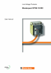
3 frame sizes, 2 families
The new range of power circuit breakers includes
two families:
b Masterpact NT, the world’s smallest true power
circuit breaker, with ratings from 800 to 1600 A
b Masterpact NW, in two frame sizes, one from
800 to 4000 A and the other from 4000 A to
6300 A.
Masterpact NT
PB100831-76
PB100726-21
800 to 1600 A
Masterpact NW
PB100747-76
PB100724-33
800 to 4000 A
PB100748-76
PB100725-57
4000 to 6300 A
7
Optimised
volumes
PB100742-39
The smallest circuit breaker in
the world
Masterpact NT innovates by offering all the
performance of a power circuit breaker in an
extremely small volume. The 70 mm pole pitch
means a three-pole drawout circuit breaker can
be installed in a switchboard section 400 mm
wide and 400 mm deep.
Practical installation solutions
PB100743-53
The new range improves upon all the installation
solutions which have already made Masterpact
a success. It has been designed to standardise
switchboards, optimise volumes and simplify
installation:
b incoming connection to top or bottom terminals
b no safety clearance required
b connection:
v horizontal or vertical rear connection
v front connection with minimum extra space
v mixed front and rear connections
b 115 mm pole pitch on all versions
b no derating up to 55 °C and 4000 A.
PB100745-71
Optimised volumes
Up to 4000 A, Masterpact NW circuit breakers
are all the same size, the same as the old M08
to 32 range.
From 4000 A to 6300 A, there is just one size,
much smaller than before.
Retrofit solutions
Special connections are available to replace a
fixed or drawout Masterpact M08 to 32 with a
Masterpact NW, without modifying the busbars
or the door cut-out.
8
Ease of
installation
PB100737-64
With optimised sizes, the Masterpact NT and NW
ranges simplify the design of switchboards and
standardise the installation of devices:
b a single connection layout for Masterpact NT
b three connection layouts for Masterpact NW:
v one from 800 to 3200 A
v one for 4000 A
v one up to 6300 A
b identical connection terminals from 800 to
6300 A (Masterpact NW)
b front connection requires little space because
the connectors to not increase the depth of the
device
rear connection to vertical or horizontal busbars
simply by turning the connectors 90°.
PB100738-81
PB100736-64
Vertical front connection of a fixed Masterpact NW.
Vertical and horizontal rear connection
of a fixed Masterpact NW.
Connection to busbars.
9
Innovation
PB100740
Greater dependability…
Filtered breaking
The patented new design of the arc chutes includes stainless-steel filters.
The chutes absorb the energy released during breaking, thus limiting the
stresses exerted on the installation. They filter and cool the gases
produced, reducing effects perceptible from the outside.
Automatic unlatching
The automatic unlatching of the circuit breaker operating mechanism for
high short-circuits extends performance up to 150 kA. It produces ultra-fast
tripping for all short-circuits higher than 37 kA (L1) and 65 kA (H3). For
lower short-circuits, the system does not react so that the control unit can
provide total discrimination with downstream devices.
Filtered breaking.
More intelligent trip units…
PB100739
Today, with the high speed of calculation, the small size of memories and
advances in miniaturisation, trip units have become circuit breaker control
units offering increasingly powerful functions. They accurately measure
system parameters, instantly calculate values, store data, log events, signal
alarms, communicate, take action, etc. The new Masterpact ranges,
equipped with Micrologic control units, constitute both an extremely reliable
protective device and an accurate measurement instrument.
User friendly…
Intuitive use…
Micrologic control units are equipped with a digital LCD display used in
conjunction with simple navigation buttons. Users can directly access
parameters and settings. Navigation between screens is intuitive and the
immediate display of values greatly simplifies settings. Text is displayed in
the desired language.
… backed by incomparable security
Navigation buttons on a Micrologic P control unit.
10
Protection functions are separate from the measurement functions and are
managed by an ASIC electronic component. This independence
guarantees immunity from conducted or radiated disturbances and ensures
a high degree of reliability.
A patented "double setting" system for protection functions establishes:
b a maximum threshold set using the control-unit dials
b fine adjustments via the keypad or remotely. The fine adjustments for
thresholds (to within one ampere) and tripping delays (to within a fraction of
a second) are displayed directly on the screen.
The control unit cover can be lead-sealed to prevent uncontrolled access to
the dials and protect the settings.
Ready for
the future
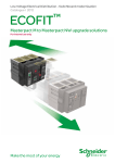
Compliance with environmental
requirements
Schneider Electric fully takes into account
environmental requirements, starting right from the
design phase of every product through to the end of
its service life:
b the materials used for Masterpact are not
potentially dangerous to the environment
b the production facilities are non-polluting in
compliance with the ISO 14001 standard
b filtered breaking eliminates pollution in the
switchboard
b the energy dissipated per pole is low, making
energy losses insignificant
b the materials are marked to facilitate sorting for
recycling at the end of product service life.
Simple upgrading of
installations
Installations change, power levels increase, new
equipment is required and switchboards must be
extended. Masterpact is designed to adapt to these
changes:
b all control units are interchangeable
b communication with a supervision system is an
option that may be added at any time
b a reserve chassis can be pre-addressed so that
system parameters do not have to be modified when
a drawout device is installed at a later date
b any future changes to the products will be
designed to ensure continuity with the current
ranges, thus simplifying installation upgrades.
11
12
Masterpact
Functions and characteristics
Presentation
6
General overview
14
Detailed contents
14
Circuit breakers and switch-disconnectors
16
NT06 to NT16 and NW08 to NW63
NT06 to NT16
NW08 to NW63
16
18
20
Micrologic control units
22
Overview of functions
Micrologic A "ammeter"
Micrologic P "power"
Micrologic H "harmonics"
Accessories and test equipment
22
24
26
30
32
Communication
34
COM option in Masterpact
Overview of functions
Masterpact in a communication network
Masterpact and the MPS100 Micro Power Server
34
35
36
38
Connections
40
Overview of solutions
Optional accessories
40
41
Locking
44
On the device
On the chassis
44
45
Indication contacts
46
Remote ON / OFF
Remote tripping
48
51
Accessories
52
Source-changeover systems
53
Presentation
Mechanical interlocking
Electrical interlocking
Associated automatic controllers
53
54
55
56
Display modules
57
Dimensions and connection
Electrical diagrams
Installation recommendations
Additional characteristics
Catalogue numbers, spare parts and order form
59
87
97
121
127
13
PB100762-60
This chapter describes all the functions
offered by Masterpact NT and NW devices.
The two product families have identical
functions implemented using the same or
different components depending on the
case.
General overview
Detailed contents
0
Circuit breakers and switch-disconnectors page 16
b
v
v
b
b
b
b
b
b
ratings:
Masterpact NT 630 to 1600 A
Masterpact NW 800 to 6300 A
circuit breakers type N1, H1, H2, H3, L1
switch-disconnectors type NA, HA, HF
3 or 4 poles
fixed or drawout versions
option with neutral on the right
protection derating.
page 22
DB101123
Micrologic control units
Ammeter A
2.0 basic protection
5.0 selective protection
6.0 selective + earth-fault protection
7.0 selective + earth-leakage protection
DB101124
Functions
and characteristics
Power meter P
5.0 selective protection
6.0 selective + earth-fault protection
7.0 selective + earth-leakage protection
Harmonic meter H
5.0 selective protection
6.0 selective + earth-fault protection
7.0 selective + earth-leakage protection
b external sensor for earth-fault protection
b rectangular sensor for earth-leakage protection
b setting options (long-time rating plug):
v low setting 0.4 to 0.8 x Ir
v high setting 0.8 to 1 x Ir
v without long-time protection
b external power-supply module
b battery module.
Communication
page 34
PB100763-56
b COM option in Masterpact
b Masterpact in a communication network
b Masterpact and the Micro Power Server MPS100.
page 40
DB101150
DB101149
DB101147
DB101156
Connections
b rear connection (horizontal or vertical)
b front connection
b mixed connections
b optional accessories
v bare-cable connectors and connector shields
v terminal shields
v vertical-connection adapters
v cable-lug adapters
v interphase barriers
v spreaders
v disconnectable front-connection adapter
v safety shutters, shutter locking blocks, shutter
position indication and locking.
14
Functions
and characteristics
General overview
Detailed contents
0
DB101109
page 44
DB101110
PB100764-56
Locking
b pushbutton locking by padlockable transparent cover
b OFF-position locking by padlock or keylock
b chassis locking in disconnected position by keylock
b chassis locking in connected, disconnected
and test positions
b door interlock (inhibits door opening with breaker
in connected position)
b racking interlock (inhibits racking with door open)
b racking interlock between crank and OFF pushbutton
b automatic spring discharge before breaker removal
b mismatch protection.
DB101112
page 46
DB101111
DB100766-56
Indication contacts
b standard or low-level contacts:
v ON/OFF indication (OF)
v "fault trip" indication (SDE)
v carriage switches for connected
(CE) disconnected (CD) and test
(CT) positions
b programmable contacts:
v 2 contacts (M2C)
v 6 contacts (M6C).
M2C contact.
OF contact.
DB101113
page 48
DB101114
Gear motor.
MX, XF and MN volage
releases.
Accessories
b
b
b
b
b
auxiliary terminal shield
operation counter
escutcheon
transparent cover for escutcheon
escutcheon blanking plate.
page 52
DB101115
DB100765-56
Remote operation
b remote ON/OFF:
v gear motor
v XF closing or MX opening voltage releases
v PF ready-to-close contact
v options: RAR automatic or Res electrical remote
reset
- BPFE electrical closing pushbutton
b remote tripping function:
v MN voltage release
- standard
- adjustable or non-adjustable delay
v or second MX voltage release.
15
Circuit breakers
and switch-disconnectors
NT06 to NT16 and NW08 to NW63
Functions
and characteristics
NT and NW selection criteria
Masterpact NT
Masterpact NW
Standard applications
Special
applications
Standard applications
NT630-1600 H1
NT630-1600 H2
NT630-1000 L1
NT630-1600 H10
NW800-1600 N1
NW800-4000 H1
Type of application
Standard
applications with
low short-circuit
currents
Applications with
medium-level
short-circuit
currents
1000 V systems,
e.g. mines and
wind power
Standard
applications with
low short-circuit
currents
Circuit breaker for
industrial sites with
high short-circuit
currents
Icu/Ics at 440 V
Icu/Ics at 1000 V
Icu/Ics at 500 V DC L/R < 15 ms
42 kA
-
50 kA
-
Limiting circuit
breaker for
protection of
cable-type feeders
or upgraded
transformer
ratings
130 kA
-
20 kA
-
42 kA
-
65 kA
-
Position of neutral
Fixed
Drawout
Switch-disconnector version
Front connection
Rear connection
Type of Micrologic control unit
Left
F
D
Yes
Yes
Yes
A, P, H
Left
F
D
No
Yes
Yes
A, P, H
Left
F
D
No
Yes
Yes
A, P, H
Left
F
D
Yes
Yes
Yes
A, consult us
for P and H
Left
F
D
Yes
Yes
Yes
A, P, H
Left or right
F
D
Yes
Yes up to 3200 A
Yes
A, P, H
Masterpact NT06 to NT16 installation characteristics
Circuit breaker
NT06, NT08, NT10
Type
NT12, NT16
H1
H2
L1
H10
H1
H2
H10
b
b
b
b
b
b
b
b
b
b
b
b
b
b
b
b
b
b
b
b
b
b
b
b
b
b
b
b
Connection
Drawout
FC
RC
Fixed
FC
RC
Dimensions (mm) H x W x D
Drawout
3P
4P
Fixed
3P
4P
Weight (kg) (approximate)
Drawout
3P/4P
Fixed
3P/4P
322 x 288 x 277
322 x 358 x 277
301 x 276 x 196
301 x 346 x 196
30/39
14/18
Masterpact NW08 to NW63 installation characteristics
Circuit breaker
NW08, NW10, NW12, NW16
Type
NW20
N1
H1
H2
L1
H10
H1
H2
H3
L1
H10
b
b
b
b
b
b
b
b
b
b
b
b
b
b
-
b
-
b
b
b
b
b
b
b
b
b
b
-
b
b
-
b
-
Connection
Drawout
FC
RC
Fixed
FC
RC
Dimensions (mm) H x W x D
Drawout
3P
4P
Fixed
3P
4P
Weight (kg) (approximate)
Drawout
3P/4P
Fixed
3P/4P
(1) Except 4000 A.
16
439 x 441 x 395
439 x 556 x 395
352 x 442 x 297
352 x 537 x 297
90/120
60/80
0
Circuit breakers
and switch-disconnectors
NT06 to NT16 and NW08 to NW63
Functions
and characteristics
0
Special applications
NW800-4000 H2
NW2000-4000 H3 NW800-2000 L1
NW H10
High-performance
circuit breaker for
heavy industry
with high shortcircuit currents
Incoming device
with very high
performance for
critical
applications
1000 V systems,
e.g. mines and
wind power
100 kA
-
150 kA
-
Limiting circuit
breaker for
protection of
cable-type feeders
or upgraded
transformer
ratings
150 kA
-
NW H2 with anti- NW1000-4000
corrosion
DC N
protection
Environments with DC system
high sulphur
contents
50 kA
-
100 kA
-
Left or right
F
D
Yes
Yes up to 3200 A
Yes
A, P, H
Left
D
Yes
Yes up to 3200 A
Yes
A, P, H
Left
D
Yes
Yes up to 3200 A
Yes
A, P, H
Left
D
Yes
No
Yes
A, consult us
for P and H
Left or right
D
Yes
Yes up to 3200 A
Yes
A, P, H
NW25, NW32, NW40
NW1000-4000
DC H
NW earthing
switch
DC system
Installation
earthing
35 kA
85 kA
-
F
D
Yes
No
Yes
DC Micrologic
F
D
Yes
No
Yes
DC Micrologic
D
Yes
Yes up to 3200 A
Yes
-
NW40b, NW50, NW63
H1
H2
H3
H10
H1
H2
b (1)
b
b (1)
b
b (1)
b
b (1)
b
b (1)
b
-
b
-
b
b
b
b
479 x 786 x 395
479 x 1016 x 395
352 x 767 x 297
352 x 997 x 297
225/300
120/160
17
Functions
and characteristics
Circuit breakers
and switch-disconnectors
NT06 to NT16
0
PB100767-48
Common characteristics
Number of poles
Rated insulation voltage (V)
Impulse withstand voltage (kV)
Rated operational voltage (V AC 50/60 Hz)
Suitability for isolation
Degree of pollution
Ui
Uimp
Ue
IEC 60947-2
IEC 60664-1
3/4
1000
12
690/1000
3
Circuit-breaker characteristics as per IEC 60947-2
Rated current (A)
Rating of 4th pole (A)
Sensor ratings (A)
Type of circuit breaker
Ultimate breaking capacity (kA rms)
V AC 50/60 Hz
In
at 40 °C/50 °C (1)
Icu
Rated service breaking capacity (kA rms)
Utilisation category
Rated short-time withstand current (kA rms)
V AC 50/60 Hz
Ics
220/415 V
440 V
525 V
690 V
1000 V
% Icu
Integrated instantaneous protection (kA peak ±10 %)
Rated making capacity (kA peak)
V AC 50/60 Hz
Icw
0.5 s
1s
3s
Icm
220/415 V
440 V
525 V
690 V
1000 V
Break time (ms) between tripping order and arc extinction
Closing time (ms)
Circuit-breaker characteristics as per NEMA AB1
Breaking capacity (kA)
V AC 50/60 Hz
240 V
480 V
600 V
Switch-disconnector characteristics as per IEC 60947-3 and Annex A
Type of switch-disconnector
Rated making capacity (kA peak)
AC23A/AC3 category V AC 50/60 Hz
Icm
Rated short-time withstand current (kA rms)
AC23A/AC3 category V AC 50/60 Hz
Icw
Ultimate breaking capacity Icu (kA rms) with an external protection relay
Maximum time delay: 350 ms
220 V
440 V
525/690 V
1000 V
0.5 s
1s
3s
690 V
Mechanical and electrical durability as per IEC 60947-2/3 at In/Ie
Service life
Mechanical
C/O cycles x 1000
Type of circuit breaker
Rated current
C/O cycles x 1000 Electrical
IEC 60947-2
(1) 50 °C: rear vertical connected. Refer to temperature
derating tables for other connection types.
(2) See the current-limiting curves in the "additional
characteristics" section.
(3) SELLIM system.
(4) Available for 480 V NEMA.
(5) Suitable for motor control (direct-on-line starting).
18
with maintenance
without maintenance
In (A)
without maintenance
Type of circuit breaker or switch-disconnector
Ie (A)
Rated operationnal current
C/O cycles x 1000 Electrical
without maintenance
IEC 60947-3
Type of circuit breaker or switch-disconnector
Ie (A)
Rated operationnal current
Motor power
C/O cycles x 1000 Electrical
IEC 60947-3 Annex M/IEC 60947-4-1
without maintenance
440 V (4)
690 V
1000 V
AC23A
440 V (4)
690V
AC3 (5)
380/415 V (kW)
440 V (kW)
440 V (4)
690 V
Circuit breakers
and switch-disconnectors
NT06 to NT16
Functions
and characteristics
0
Sensor selection
Sensor rating (A)
250 (1)
Ir thresold setting(A)
100 to 250
(1) For NT02 rating, please consult us.
400
160 to 400
630
250 to 630
800
320 to 800
1000
400 to 1000
1250
500 to 1250
1600
640 to 1600
NT06
NT08
NT10
NT12
NT16
630
630
400 to 630
H1
H2
42
50
42
50
42
42
42
42
100 %
B
B
42
36
42
36
24
20
90
88
105
88
105
88
88
88
88
25
25
< 50
800
800
400 to 800
1000
1000
400 to 1000
1250
1250
630 to 1250
H1
H2
42
50
42
50
42
42
42
42
100 %
B
B
42
36
36
24
20
90
88
105
88
105
88
88
88
88
25
25
< 50
1600
1600
800 to 1600
42
42
42
50
50
42
HA
75
75
75
36
36
20
36
HA10
42
20
20
20
25
12.5
H1
H2
630
6
6
3
3
H1/H2/HA
630
6
3
H1/H2/HA
500
y 250
y 300
6
-
L1 (2)
150
130
100
25
-
H10
20
A
10
10 x In (3)
330
286
220
52
9
B
20
20
42
-
150
100
25
-
L1
H10
3
2
-
0.5
42
42
42
H1
800
6
3
-
H2
L1
H10
6
3
-
3
2
-
0.5
H1
1000
6
3
-
H2
L1
H10
6
3
-
3
2
-
0.5
50
50
42
H10
20
B
20
20
42
-
-
HA
75
75
75
36
36
20
36
HA10
42
20
20
20
H1
1250
6
3
-
H2
H10
6
3
-
0.5
H10
1600
0.5
H1
H2
6
3
-
6
3
-
800
6
3
1000
6
3
1250
6
3
1600
6
3
630
250 to 335
300 to 400
800
335 to 450
400 to 500
1000
450 to 560
500 to 630
1000
450 to 560
500 to 630
19
Functions
and characteristics
Circuit breakers
and switch-disconnectors
NW08 to NW63
0
PB100768-38
Common characteristics
Number of poles
Rated insulation voltage (V)
Impulse withstand voltage (kV)
Rated operational voltage (V AC 50/60 Hz)
Suitability for isolation
Degree of pollution
Ui
Uimp
Ue
IEC 60947-2
IEC 60664-1
3/4
1000/1250
12
690/1150
4 (1000 V) / 3 (1250 V)
Circuit-breaker characteristics as per IEC 60947-2
at 40 °C / 50 °C (1)
Rated current (A)
Rating of 4th pole (A)
Sensor ratings (A)
PB100769-70
Type of circuit breaker
Ultimate breaking capacity (kA rms)
V AC 50/60 Hz
Icu
Rated service breaking capacity (kA rms)
Utilisation category
Rated short-time withstand current (kA rms)
V AC 50/60 Hz
Integrated instantaneous protection (kA peak ±10 %)
Rated making capacity (kA peak)
V AC 50/60 Hz
Ics
220/415/440 V
525 V
690 V
1150 V
% Icu
Icw
1s
3s
Icm
220/415/440 V
525 V
690 V
1150 V
Break time (ms) between tripping order and arc extinction
Closing time (ms)
Circuit-breaker characteristics as per NEMA AB1
Breaking capacity (kA)
V AC 50/60 Hz
240/480 V
600 V
Unprotected circuit-breaker characteristics:
Tripping by shunt trip as per IEC 60947-2
Type of circuit breaker
Ultimate breaking capacity (kA rms) V AC 50/60 Hz
Rated service breaking capacity (kA rms)
Rated short-time withstand current (kA rms)
Icu
Ics
Icw
220...690 V
% Icu
1s
3s
Overload and short-circuit protection with external protection relay:
short-circuit protection, maximum delay: 350 ms (4)
Rated making capacity (kA peak) V AC 50/60 Hz
Icm
220...690 V
Switch-disconnector characteristics as per IEC 60947-3
and Annex A
Type of switch-disconnector
Rated making capacity (kA peak)
AC23A/AC3 category V AC 50/60 Hz
Icm
Rated short-time withstand current (kA rms)
AC23A/AC3 category V AC 50/60 Hz
Icw
220...690 V
1150 V
0.5 s
1s
3s
Mechanical and electrical durability as per IEC 60947-2/3 at In/Ie
Service life
Mechanical with maintenance
C/O cycles x 1000
without maintenance
Type of circuit breaker
In (A)
Rated current
C/O cycles x 1000
Electrical
without maintenance
IEC 60947-2
(1) 50 °C: rear vertical connected. Refer to temperature
derating tables for other connection types.
(2) See the current-limiting curves in the "additional
characteristics" section.
(3) Equipped with a trip unit with a making current
of 90 kA peak.
(4) External protection must comply with permissible thermal
constraints of the circuit breaker (please consult us).
No fault-trip indication by the SDE or the reset button.
(5) Available for 480 V NEMA.
(6) Suitable for motor control (direct-on-line starting).
20
Type of circuit breaker or switch-disconnector
Ie (A)
Rated operational current
C/O cycles x 1000
Electrical
without maintenance
IEC 60947-3
Type of circuit breaker or switch-disconnector
Ie (A)
Rated operational current
Motor power
C/O cycles x 1000
Electrical
IEC 60947-3 Annex M/IEC 60947-4-1
without maintenance
440 V (5)
690 V
1150 V
AC23A
440 V (5)
690 V
AC3 (6)
380/415 V (kW)
440 V (5) (kW)
690 V (kW)
440/690 V (5)
Circuit breakers
and switch-disconnectors
NW08 to NW63
Functions
and characteristics
0
Sensor selection
250 (1)
100
to 250
(1) For NW02 rating, please consult us.
Sensor rating (A)
Ir thresold setting(A)
400
160
to 400
630
250
to 630
NW08 NW10 NW12 NW16
NW20
800
800
400
to 800
N1
42
42
42
100 %
B
42
22
Without
88
88
88
25
< 70
2000
2000
1000 to 2000
42
42
1000
1000
400
to 1000
H1
65
65
65
-
1250
1250
630
to 1250
H2
100
85
85
-
1600
1600
800 to 1600
65
36
Without
143
143
143
25
85
50
190
220
187
187
25
30
30
80
330
286
220
10
65
65
100
85
150
100
HA
50
HF (3)
85
L1 (2)
150
130
100
-
1000
1250
1600
2000
400
500
630
800
to 1000 to 1250 to 1600 to 2000
H3
150
130
100
-
85
75
190
220
187
187
25
65
65
150
330
286
220
25
65
65
100
85
150
100
HF (3)
85
85
75
Without
HA
85
100 %
85
85
Without
187
187
L1 (2)
150
130
100
-
85
75
190
220
187
187
25
65
65
150
330
286
220
25
30
30
80
330
286
220
10
65
65
100
85
150
100
150
100
HF (3)
85
50
85
36
50
Without Without
HA
50
100 %
50
36
Without
85
75
Without
HA
55
100 %
55
55
Without
105
105
187
121
-
187
NW08/NW10/NW12
HA
105
50
36
25
12.5
N1/H1/H2 L1
800/1000/1250/1600
10
3
10
3
H1/H2/NA/HA/HF
800/1000/1250/1600
10
10
H1/H2/HA/HF
800
1000
335 to 450 450 to 560
400 to 500 500 to 630
800 to 1000
y 800
6
HF
187
85
50
NW16
HA10
105
50
50
HA
105
50
50
NW20
HF
187
85
50
H10
0.5
1250
560 to 670
500 to 800
1000 to 1250
-
1600
670 to 900
800 to 1000
1250 to 1600
HA10
105
50
50
HA
105
50
50
NW40b NW50 NW63
3200
3200
1600
to 3200
H2
100
85
85
-
H3
150
130
100
-
H1
65
65
65
100 %
B
50
65
50
36
Without Without
143
143
143
105
25
25
< 70
2500
3200
4000
5000
6300
1000
1250
1600
2000
2500
to 2500 to 3200 to 4000 to 5000 to 6300
NW25 NW32 NW40
2500
2500
1250
to 2500
H10
H1
65
65
65
50
100 %
B
50
65
50
65
Without Without
143
143
143
105
25
25
< 70
H2
100
85
85
-
H10
50
100 %
NA
88
42
-
800
320
to 800
4000
4000
2000 to 4000
4000
4000
2000
to 4000
H10
H1
100
100
100
50
100 %
B
50
100
50
100
Without Without
220
220
220
105
25
25
< 80
-
100
100
5000
5000
2500
to 5000
H2
150
130
100
-
6300
6300
3200
to 6300
100
100
270
330
286
220
25
150
100
NW25/NW32/NW40 NW40b/NW50/NW63
HF
187
85
50
HA10
105
50
50
20
10
H1/H2 L1
H10
2000
8
3
6
3
0.5
H1/H2/H3/HA/HF
2000
8
6
H1/H2/H3/HA/HF
2000
900 to 1150
1000 to 1300
1600 to 2000
HA
121
55
55
HF
187
85
75
H1/H2 H3
2500/3200/4000
5
1.25
2.5
1.25
2500/3200/4000
5
2.5
HA10
105
50
50
H10
0.5
HA
187
85
85
10
5
H1
H2
4000b/5000/6300
1.5
1.5
1.5
1.5
H1/H2/HA
4000b/5000/6300
1.5
1.5
21
Micrologic control units
Overview of functions
Functions
and characteristics
Dependability
All Masterpact circuit breakers are equipped
with a Micrologic control unit that can be
changed on site.
Control units are designed to protect Power
circuits and loads. Alarms may be
programmed for remote indications.
Measurements of current, voltage,
frequency, power and power quality
optimise continuity of service and energy
management.
Integration of protection functions in an ASIC electronic component used in all
Micrologic control units guarantees a high degree of reliability and immunity to
conducted or radiated disturbances.
On Micrologic A, P and H control units, advanced functions are managed by an
independent microprocessor.
Micrologic name codes
Current protection
Micrologic 2: basic protection
Y
Z
Protection:
long time
+ instantaneous
DB101116
2.0 A
X
0
X: type of protection
b 2 for basic protection
b 5 for selective protection
b 6 for selective + earth-fault protection
b 7 for selective + earth-leakage protection.
Y: control-unit generation
Identification of the control-unit generation.
"0" signifies the first generation.
Protection:
long time
+ short time
+ instantaneous
DB101117
PB100772-32
Z: type of measurement
b A for "ammeter"
b P for "power meter"
b H for "harmonic meter".
Micrologic 5: basic protection
DB101118
DB101117
Micrologic 6: selective + earth-fault protection
Protection:
long time
+ short time
+ instantaneous
+ earth fault
22
DB101119
DB101117
Micrologic 7: selective + earth-leakage protection
Protection:
long time
+ short time
+ instantaneous
+ earth leakage
Micrologic control units
Overview of functions
Functions
and characteristics
0
Measurements and programmable protection
A: ammeter
b I1, I2, I3, IN, Iearth-fault, Iearth-leakage and maximeter for these measurements
b fault indications
b settings in amperes and in seconds.
P: A + power meter + programmable protection
b measurements of V, A, W, VAR, VA, Wh, VARh, VAh, Hz, Vpeak, Apeak, power factor and maximeters and minimeters
b IDMTL long-time protection, minimum and maximum voltage and frequency, voltage and current imbalance,
phase sequence, reverse power
b load shedding and reconnection depending on power or current
b measurements of interrupted currents, differentiated fault indications, maintenance indications, event histories
and time-stamping, etc.
H: P + harmonics
b power quality: fundamentals, distortion, amplitude and phase of harmonics up to the
31st order
b waveform capture after fault, alarm or on request
b enhanced alarm programming: thresholds and actions.
DB101120
2.0 A
DB101122
DB101124
DB101124
7.0 H
DB101124
7.0 P
DB101123
7.0 A
6.0 H
DB101124
6.0 P
DB101123
6.0 A
5.0 H
DB101122
5.0 P
DB101121
5.0 A
23
Functions
and characteristics
Micrologic control units
Micrologic A "ammeter"
Micrologic A control units protect power
circuits.
They also offer measurements, display,
communication and current maximeters.
Version 6 provides earth-fault protection,
version 7 provides earth-leakage protection.
Protection settings ..................................................................
Protection thresholds and delays are set using the adjustment dials.
The selected values are momentarily displayed in amperes and in seconds.
Overload protection
True rms long-time protection.
Thermal memory: thermal image before and after tripping.
Setting accuracy may be enhanced by limiting the setting range using a different
long-time rating plug.
The long-time rating plug "OFF" enables to cancel the overload protection.
DB101125
Short-circuit protection
Short-time (rms) and instantaneous protection.
Selection of I2t type (ON or OFF) for short-time delay.
Earth fault protection
Residual or source ground return.
Selection of I2t type (ON or OFF) for delay.
Residual earth-leakage protection (Vigi).
Operation without an external power supply.
q Protected against nuisance tripping.
k DC-component withstand class A up to 10 A.
Neutral protection
On three-pole circuit breakers, neutral protection is not possible.
On four-pole circuit breakers, neutral protection may be set using a three-position
switch: neutral unprotected (4P 3d), neutral protection at 0.5 In (4P 3d + N/2), neutral
protection at In (4P 4d).
Zone selective interlocking (ZSI)
A ZSI terminal block may be used to interconnect a number of control units to provide
total discrimination for short-time and earth-fault protection, without a delay before
tripping.
"Ammeter" measurements .....................................................
Micrologic A control units measure the true rms value of currents.
They provide continuous current measurements from 0.2 to 20 In and are accurate
to within 1.5% (including the sensors).
A digital LCD screen continuously displays the most heavily loaded phase (Imax) or
displays the I1, I2, I3, IN, Ig, I∆n, stored-current (maximeter) and setting values by
successively pressing the navigation button.
The optional external power supply makes it possible to display currents < 20 % In.
Below 0.05 In, measurements are not significant. Between 0.05 and 0.2 In, accuracy
is to within 0.5% In + 1.5% of the reading.
Communication option
In conjunction with the COM communication option, the control unit transmits the
following:
b setting values
b all "ammeter" measurements
b tripping causes
b maximeter reset.
1
2
3
4
5
6
7
8
9
10
11
12
13
Long-time current setting and tripping delay.
Overload signal (LED) at 1.125 Ir.
Short-time pick-up and tripping delay.
Instantaneous pick-up.
Earth-leakage or earth-fault pick-up and tripping delay.
Earth-leakage or earth-fault test button.
Long-time rating plug screw.
Test connector.
Lamp test, reset and battery test.
Indication of tripping cause.
Digital display.
Three-phase bargraph and ammeter.
Navigation buttons.
Note: Micrologic A control units come with a transparent leadseal cover as standard.
24
0
Micrologic control units
Micrologic A "ammeter"
Functions
and characteristics
Micrologic 2.0 A
Long time
Current setting (A)
Ir = In x …
Tripping between 1.05 and 1.20 x Ir
Time setting
Time delay (s)
Accuracy: 0 to -30 %
Accuracy: 0 to -20 %
Accuracy: 0 to -20 %
Thermal memory
(1) 0 to -40 % - (2) 0 to -60 %
Instantaneous
Pick-up (A)
Isd = Ir x …
Accuracy: ±10 %
Time delay
tr (s)
1.5 x Ir
6 x Ir
7.2 x Ir
1.5
Ammeter
4
5
6
8
10
5
6
8
10
8
10
12
15
off
D
0.5
0.5
800
0.3
0.3
230
320
E
0.6
0.6
880
0.4
0.4
350
500
F
0.7
0.7
960
G
0.8
0.8
1040
H
0.9
0.9
1120
J
1
1
1200
DB101128
3
5
7
10
20
30
350
350
500
800
800
1000
DB101129
tr (s)
1.5 x Ir
6 x Ir
7.2 x Ir
Micrologic 5.0 / 6.0 / 7.0 A
0.4
0.5
0.6
0.7
0.8
0.9
0.95 0.98 1
Other ranges or disable by changing long-time rating plug
0.5
1
2
4
8
12
16
20
24
12.5 25
50
100 200 300 400 500 600
0.7(1) 1
2
4
8
12
16
20
24
0.7(2) 0.69 1.38 2.7
5.5
8.3
11
13.8 16.6
20 minutes before and after tripping
1.5
2
2.5
3
4
I2t Off
I2t On
tsd (max resettable time)
tsd (max break time)
0
20
80
0.1
0.1
80
140
0.2
0.2
140
200
0.3
0.3
230
320
0.4
0.4
350
500
Ii = In x …
2
3
4
6
DB101127
Micrologic 5.0 / 6.0 / 7.0 A
Long time
Current setting (A)
Ir = In x …
Tripping between 1.05 and 1.20 x Ir
Time setting
Time delay (s)
Accuracy: 0 to -30 %
Accuracy: 0 to -20 %
Accuracy: 0 to -20 %
Thermal memory
(1) 0 to -40 % - (2) 0 to -60 %
Short time
Pick-up (A)
Isd = Ir x …
Accuracy: ±10 %
Time setting tsd (s)
Settings
Time delay (ms)
at In or 1200 A (I2t Off or I2t On)
Residual earth leakage (Vigi)
Sensitivity (A)
Accuracy: 0 to -20 %
Time delay ∆t (ms)
3
I1
I2
I3
IN
No auxiliary source (where I > 20 % In)
I1 max I2 max I3 max IN max
Protection
Time setting tg (s)
2.5
Micrologic 2.0 A
Continuous current measurements
Display from 20 to 200 % of In
Accuracy: 1.5 % (including sensors)
Maximeters
Earth fault
Pick-up (A)
Accuracy: ±10 %
2
Max resettable time: 20 ms
Max break time: 80 ms
Ammeter
Time delay (ms) at 10 x Ir
(I2t Off or I2t On)
Instantaneous
Pick-up (A)
Accuracy: ±10 %
Time delay
0.4
0.5
0.6
0.7
0.8
0.9
0.95 0.98 1
Other ranges or disable by changing long-time rating plug
0.5
1
2
4
8
12
16
20
24
12.5 25
50
100 200 300 400 500 600
0.7(1) 1
2
4
8
12
16
20
24
5.5
8.3
11
13.8 16.6
0.7(2) 0.69 1.38 2.7
20 minutes before and after tripping
DB101126
Protection
0
Max resettable time: 20 ms
Max break time: 80 ms
I∆n
Micrologic 6.0 A
A
B
C
0.3
0.3
0.4
0.2
0.3
0.4
500 640 720
0
0.1
0.2
0.1
0.2
20
80
140
80
140 200
Micrologic 7.0 A
0.5
1
2
Settings
∆t (max resettable time)
∆t (max break time)
60
60
140
Ig = In x …
In y 400 A
400 A < In < 1250 A
In u 1250 A
Settings
I2t Off
I2t On
tg (max resettable time)
tg (max break time)
140
140
200
230
230
320
Micrologic 5.0 / 6.0 / 7.0 A
Continuous current measurements
Display from 20 to 200 % of In
I1
I2
I3
IN
Ig
I∆n
Accuracy: 1.5 % (including sensors)
No auxiliary source (where I > 20 % In)
Maximeters
I1 max I2 max I3 max IN max Ig max I∆n max
Note: All current-based protection functions require no auxiliary source.
The test / reset button resets maximeters, clears the tripping indication and tests the battery.
25
Functions
and characteristics
Micrologic control units
Micrologic P "power"
Micrologic P control units include all the
functions offered by Micrologic A.
In addition, they measure voltages and
calculate power and energy values.
They also offer new protection functions
based on currents, voltages, frequency and
power reinforce load protection.
Protection settings .......................................................
0
+
The adjustable protection functions are identical to those of Micrologic A (overloads,
short-circuits, earth-fault and earth-leakage protection).
Fine adjustment
Within the range determined by the adjustment dial, fine adjustment of thresholds (to
within one ampere) and time delays (to within one second) is possible on the keypad
or remotely using the COM option.
IDMTL (Inverse Definite Minimum Time lag) setting
Coordination with fuse-type or medium-voltage protection systems is optimised by
adjusting the slope of the overload-protection curve. This setting also ensures better
operation of this protection function with certain loads.
DB101485
Neutral protection
On three-pole circuit breakers, neutral protection may be set using the keypad or
remotely using the COM option, to one of four positions: neutral unprotected (4P 3d),
neutral protection at 0.5 In (4P 3d + N/2), neutral protection at In (4P 4d) and neutral
protection at 1,6 In (4P 3d + 1,6N). Neutral protection at 1,6 In is used when the
neutral conductor is twice the size of the phase conductors (major load imbalance,
high level of third order harmonics).
On four-pole circuit breakers, neutral protection may be set using a three-position
switch or the keypad: neutral unprotected (4P 3d), neutral protection at 0.5 In (4P 3d
+ N/2), neutral protection at In (4P 4d). Neutral protection produces no effect if the
long-time curve is set to one of the IDMTL protection settings.
Programmable alarms and other protection..................... ....
Depending on the thresholds and time delays set using the keypad or remotely using
the COM option, the Micrologic P control unit monitors currents and voltage, power,
frequency and the phase sequence. Each threshold overrun is signalled remotely via
the COM option. Each threshold overrun may be combined with tripping (protection)
or an indication carried out by an optional M2C or M6C programmable contact
(alarm), or both (protection and alarm).
Load shedding and reconnection..........................................
Load shedding and reconnection parameters may be set according to the power or
the current flowing through the circuit breaker. Load shedding is carried out by a
supervisor via the COM option or by an M2C or M6C programmable contact.
Measurements..........................................................................
The Micrologic P control unit calculates in real time all the electrical values (V, A, W,
VAR, VA, Wh, VARh, VAh, Hz), power factors and crest factors.
The Micrologic P control unit also calculates demand current and demand power
over an adjustable time period. Each measurement is associated with a minimeter
and a maximeter.
In the event of tripping on a fault, the interrupted current is stored. The optional
external power supply makes it possible to display the value with the circuit breaker
open or not supplied.
Histories and maintenance indicators...................................
The last ten trips and alarms are recorded in two separate history files. Maintenance
indications (contact wear, operation cycles, etc.) are recorded for local access.
Indication option via programmable contacts
1
2
3
4
5
6
7
8
9
10
11
12
13
14
15
16
Long-time current setting and tripping delay.
Overload signal (LED).
Short-time pick-up and tripping delay.
Instantaneous pick-up.
Earth-leakage or earth-fault pick-up and tripping delay.
Earth-leakage or earth-fault test button.
Long-time rating plug screw.
Test connector.
Lamp + battery test and indications reset.
Indication of tripping cause.
High-resolution screen.
Measurement display.
Maintenance indicators.
Protection settings.
Navigation buttons.
Hole for settings lockout pin on cover.
Note: Micrologic P control units come with a non-transparent
lead-seal cover as standard.
26
The M2C (two contacts) and M6C (six contacts) auxiliary contacts may be used to
signal threshold overruns or status changes. They can be programmed using the
keypad on the Micrologic P control unit or remotely using the COM option.
Communication option (COM)
The communication option may be used to:
b remotely read and set parameters for the protection functions
b transmit all the calculated indicators and measurements
b signal the causes of tripping and alarms
b consult the history files and the maintenance-indicator register.
b maximeter reset.
An event log and a maintenance register, stored in control-unit memory but not
available locally, may be accessed in addition via the COM option.
Micrologic control units
Micrologic P "power"
Functions
and characteristics
Micrologic 5.0 / 6.0 / 7.0 P
Earth fault
Pick-up (A)
Accuracy: ±10 %
Time setting tg (s)
Time delay (ms)
at In or 1200 A (I2t Off or I2t On)
Residual earth leakage (Vigi)
Sensitivity (A)
Accuracy: 0 to -20 %
Time delay ∆t (ms)
2
2.5
3
4
I2t Off
I2t On
tsd (max resettable time)
tsd (max break time)
0
20
80
0.1
0.1
80
140
0.2
0.2
140
200
0.3
0.3
230
320
0.4
0.4
350
500
Ii = In x …
2
3
4
6
Voltage
Voltage unbalance
Minimum voltage
Maximum voltage
Power
Reverse power
Frequency
Minimum frequency
Maximum frequency
Phase sequence
Sequense (alarm)
I∆n
Micrologic 6.0 P
A
B
C
0.3 0.3
0.4
0.2 0.3
0.4
500 640 720
0
0.1
0.2
0.1
0.2
20
80
140
80
140 200
Micrologic 7.0 P
0.5 1
2
Settings
∆t (max resettable time)
∆t (max break time)
60
60
140
Ig = In x …
In y 400 A
400 A < In < 1250 A
In u 1250 A
Settings
I2t Off
I2t On
tg (max resettable time)
tg (max break time)
8
10
8
10
12
15
off
D
0.5
0.5
800
0.3
0.3
230
320
E
0.6
0.6
880
0.4
0.4
350
500
F
0.7
0.7
960
G
0.8
0.8
1040
H
0.9
0.9
1120
J
1
1
1200
3
5
7
10
20
30
140
140
200
230
230
320
350
350
500
800
800
1000
Seuil
0.05 to 0.6 Iaverage
0.2 In to In
Temporisation
1 to 40 s
15 to 1500 s
It
20 A to 1200 A
1 to 10 s
Uunbalance
Umin
Umax
2 to 30 % x Uaverage
1 to 40 s
100 to Umax between phases 1.2 to 5 s
Umin to 1200 between phases 1.2 to 5 s
rP
5 to 500 kW
0.2 to 20 s
Fmin
Fmax
45 to Fmax
Fmin to 440 Hz
1.2 to 5 s
1.2 to 5 s
Ư
Ø1/2/3 or Ø1/3/2
0.3 s
I
P
DB101130
Micrologic 5.0 / 6.0 / 7.0 P
Iunbalance
Imax demand : I1, I2, I3, IN,
Load shedding and reconnection
Measured value
Current
Power
6
Max resettable time: 20 ms
Max break time: 80 ms
Alarms and other protection
Current
Déséquilibre de courant
Max. de courant moyen
Earth fault alarm
5
DB101128
1.5
DB101129
Time delay (ms) at 10 Ir
(I2t Off or I2t On)
Instantaneous
Pick-up (A)
Accuracy: ±10 %
Time delay
tr (s)
1.5 x Ir
6 x Ir
7.2 x Ir
Micrologic 5.0 / 6.0 / 7.0 P
0.4 0.5
0.6 0.7
0.8 0.9 0.95 0.98 1
Other ranges or disable by changing long-time rating plug
0.5 1
2
4
8
12
16
20
24
12.5 25
50
100
200 300 400 500 600
0.7(1) 1
2
4
8
12
16
20
24
5.5 8.3 11
13.8 16.6
0.7(2) 0.69 1.38 2.7
SIT VIT EIT HVFuse DT
20 minutes before and after tripping
DB101142
Long time (rms)
Current setting (A)
Ir = In x …
Tripping between 1.05 and 1.20 x Ir
Time setting
Time delay (s)
Accuracy: 0 to -30 %
Accuracy: 0 to -20 %
Accuracy: 0 to -20 %
IDMTL setting
Curve slope
Thermal memory
(1) 0 to -40 % - (2) 0 to -60 %
Short time (rms)
Pick-up (A)
Isd = Ir x …
Accuracy: ±10 %
Time setting tsd (s)
Settings
+
Micrologic 5.0 / 6.0 / 7.0 P
Seuil
0.5 to 1 Ir per phases
200 kW to 10 MW
Temporisation
20 % tr to 80 % tr
10 to 3600 s
DB101143
Protection
0
Note: all current-based protection functions require no auxiliary source.
Voltage-based protection functions are connected to AC power via a voltage measurement input built into the circuit breaker.
27
Micrologic control units
Micrologic P "power"
0
Navigation from one display to another is intuitive. The six buttons on the keypad
provide access to the menus and easy selection of values. When the setting cover is
closed, the keypad may no longer be used to access the protection settings, but still
provides access to the displays for measurements, histories, indicators, etc.
DB101134
DB101133
Functions
and characteristics
Measurements..........................................................................
Instantaneous values
The value displayed on the screen is refreshed every second.
Minimum and maximum values of measurements are stored in memory (minimeters
and maximeters).
Currents
I rms
Display of a maximum current.
Display of a power.
Power factor
Frequencies
F
1
E-fault
1
E-fault
2
V
V
V
%
12
23
31
1N
2N
3N
(U12 + U23 + U31) / 3
2
3
N
E-leakage
3
N
E-leakage
W, Var, VA
Totals
Wh, VARh, VAh Totals consumed - supplied
Totals consumed
Totals supplied
PF
Total
Hz
Demand metering
The demand is calculated over a fixed or sliding time window that may be
programmed from 5 to 60 minutes. According to the contract signed with the power
supplier, an indicator associated with a load shedding function makes it possible to
avoid or minimise the costs of overrunning the subscribed power. Maximum demand
values are systematically stored and time stamped (maximeter).
DB101138
DB101137
Display of a voltage.
I max rms
Voltages
U rms
V rms
U average rms
U unbalance
Power, energy
P active, Q reactive, S apparent
E active, E reactive, E apparent
DB101136
DB101135
Default display.
A
A
A
A
Currents
I demand
I max demand
A
A
A
A
1
E-fault
1
E-fault
W, Var, VA
W, Var, VA
Totals
Totals
2
2
3
N
E-leakage
3
N
E-leakage
Power
Display of a frequency.
Display of a demand power.
P, Q, S demand
P, Q, S max demand
Minimeters and maximeters
Only the current and power maximeters may be displayed on the screen.
DB101140
DB101139
Histories ...................................................................................
Display of a tripping history.
Display after tripping.
The last ten trips and alarms are recorded in two separate history files that may be
displayed on the screen.
b tripping history:
v type of fault
v date and time
v values measured at the time of tripping (interrupted current, etc.)
b alarm history:
v type of alarm
v date and time
v values measured at the time of the alarm.
Maintenance indicators (with COM option)...........................
A number of maintenance indicators may be called up on the screen:
b contact wear
b operation counter:
v cumulative total
v total since last reset.
28
Functions
and characteristics
Micrologic control units
Micrologic P "power"
0
DB101523
With the communication option
Additional measurements, maximeters and minimeters
Certain measured or calculated values are only accessible with the COM
communication option:
b I peak / 2, (I1 + I2 + I3)/3, I unbalance
b load level in % Ir
b total power factor.
The maximeters and minimeters are available only via the COM option for use with
a supervisor.
Display of an event log on a supervisor.
Event log
All events are time stamped.
b trips
b beginning and end of alarms
b modifications to settings and parameters
b counter resets
b system faults:
b fallback position
b thermal self-protection
b loss of time
b overrun of wear indicators
b test-kit connections
b etc.
Maintenance register
Used as an aid in troubleshooting and to better plan for device maintenance
operations.
b highest current measured
b operation counter
b number of test-kit connections
b number of trips in operating mode and in test mode
b contact-wear indicator.
Additional technical characteristics
Setting the display language
System messages may be displayed in six different languages. The desired
language is selected via the keypad.
Protection functions
All current-based protection functions require no auxiliary source. Voltage-based
protection functions are connected to AC power via a voltage measurement input
built into the circuit breaker.
Measurement functions
Measurement functions are independent of the protection functions.
The high-accuracy measurement module operates independently of the protection
module, while remaining synchronised with protection events.
Measurement-calculation mode
b measurement functions implement the new "zero blind time" concept which
consists in continuously measuring signals at a high sampling rate. The traditional
"blind window" used to process samples no longer exists. This method ensures
accurate energy calculations even for highly variable loads (welding machines,
robots, etc.)
b energies are calculated on the basis of the instantaneous power values, in two
manners:
v the traditional mode where only positive (consumed) energies are considered
v the signed mode where the positive (consumed) and negative (supplied) energies
are considered separately.
Accuracy of measurements (including sensors)
b voltage (V) 0.5 %
b current (A) 1.5 %
b frequency (Hz) 0.1 %
b power (W) and energy (Wh) 2 %.
Stored information
The fine setting adjustments, the last 100 events and the maintenance register
remain in the control-unit memory even when power is lost.
Time-stamping
Time-stamping is activated as soon as time is set manually or by a supervisor.
No external power supply module is required (max. drift of 1 hour per year).
Reset
An individual reset, via the keypad or remotely, acts on alarms, minimum and
maximum data, peak values, the counters and the indicators.
29
Micrologic control units
Micrologic H "harmonics"
Micrologic H control units include all the
functions offered by Micrologic P.
Integrating significantly enhanced
calculation and memory functions, the
Micrologic H control unit offers in-depth
analysis of power quality and detailed event
diagnostics. It is intended for operation with
a supervisor.
In addition to the Micrologic P functions, the Micrologic H control unit offers:
b in-depth analysis of power quality including calculation of harmonics and the
fundamentals
b diagnostics aid and event analysis through waveform capture
b enhanced alarm programming to analyse and track down a disturbance on the AC
power system.
DB101486
Functions
and characteristics
0
Measurements..........................................................................
The Micrologic H control unit offers all the measurements carried out by Micrologic
P, with in addition:
b phase by phase measurements of:
v power, energy
v power factors
b calculation of:
v current and voltage total harmonic distortion (THD)
v current, voltage and power fundamentals
v current and voltage harmonics up to the 31st order.
Instantaneous values displayed on the screen
Currents
I rms
I max rms
A
A
A
A
1
E-fault
1
E-fault
2
V
V
V
%
12
23
31
1N
2N
3N
(U12 + U23 + U31) / 3
2
3
N
E-leakage
3
N
E-leakage
Voltages
U rms
V rms
U average rms
U unbalance
Power, energy
P active, Q reactive, S apparent W, Var, VA
Totals
1
2
E active, E reactive, E apparent Wh, VARh, VAh Totals consumed - supplied
Totals consumed
Totals supplied
Power factor
PF
Total
1
2
3
3
Frequencies
F
Hz
Power-quality indicators
Total fundamentals
U I P Q S
THD
%
U I
U and Iharmonics
Amplitude
3 5 7 9 11 13
Harmonics 3, 5, 7, 9, 11 and 13, monitored by electrical utilities, are displayed on the screen.
Demand measurements
Similar to the Micrologic P control unit, the demand values are calculated over a fixed
or sliding time window that may be set from 5 to 60 minutes.
Currents
I demand
I max demand
A
A
A
A
1
E-fault
1
E-fault
W, Var, VA
W, Var, VA
Totals
Totals
2
2
Power
P, Q, S demand
P, Q, S max demand
Maximeters
Only the current maximeters may be displayed on the screen.
Histories and maintenance indicators
These functions are identical to those of the Micrologic P.
Note: Micrologic H control units come with a non-transparent
lead-seal cover as standard.
30
3
N
E-leakage
3
N
E-leakage
Functions
and characteristics
Micrologic control units
Micrologic H "harmonics"
0
DB101521
With the communication option
Additional measurements, maximeters and minimeters
Certain measured or calculated values are only accessible with the COM
communication option:
b I peak / 2 (I1 + I2 + I3)/3, Iunbalance
b load level in % Ir
b power factor (total and per phase)
b voltage and current THD
b K factors of currents and average K factor
b crest factors of currents and voltages
b all the fundamentals per phase
b fundamental current and voltage phase displacement
b distortion power and distortion factor phase by phase
b amplitude and displacement of current and voltage harmonics 3 to 31.
The maximeters and minimeters are available only via the COM option for use with
a supervisor.
DB101522
Display of harmonics up to 21th order.
Waveform capture
The Micrologic H control unit stores the last 4 cycles of each instantaneous current
or voltage measurement. On request or automatically on programmed events, the
control unit stores the waveforms. The waveforms may be displayed in the form of
oscillograms by a supervisor via the COM option. Definition is 64 points per cycle.
Pre-defined analogue alarms (1 to 53)
Each alarm can be compared to user-set high and low thresholds. Overrun of a
threshold generates an alarm. An alarm or combinations of alarms can be linked to
programmable action such as selective recording of measurements in a log,
waveform capture, etc.
Event log and maintenance registers
The Micrologic H offers the same event log and maintenance register functions as
the Micrologic P. In addition, it produces a log of the minimums and maximums for
each "real-time" value.
Additional technical characteristics
DB101523
Waveform capture.
Setting the display language
System messages may be displayed in six different languages. The desired
language is selected via the keypad.
Protection functions
All current-based protection functions require no auxiliary source. Voltage-based
protection functions are connected to AC power via a voltage measurement input
built into the circuit breaker.
Measurement functions
Measurement functions are independent of the protection functions.
The high-accuracy measurement module operates independently of the protection
module, while remaining synchronised with protection events.
Log.
Measurement-calculation mode
An analogue calculation function dedicated to measurements enhances the
accuracy of harmonic calculations and the power-quality indicators. The Micrologic
H control unit calculates electrical magnitudes using 1.5 x In dynamics (20 x In for
Micrologic P).
Measurement functions implement the new "zero blind time" concept
Energies are calculated on the basis of the instantaneous power values, in the
traditional and signed modes.
Harmonic components are calculated using the discrete Fourier transform (DFT).
Accuracy of measurements (including sensors)
b voltage (V) 0.5 %
b current (A) 1.5 %
b frequency (Hz) 0.1 %
b power (W) and energy (Wh) 2 %
b total harmonic distortion 1 %
Stored information
The fine-setting adjustments, the last 100 events and the maintenance register
remain in the control-unit memory even when power is lost.
Time-stamping
Time-stamping is activated as soon as time is set manually or by a supervisor no
external power supply module is required (max. drift of 1 hour per year).
Reset
An individual reset, via the keypad or remotely, acts on alarms, minimum and
maximum data, peak values, the counters and the indicators.
31
Functions
and characteristics
Micrologic control units
Accessories and test equipment
0
DB101524
External sensors
PB100834-48
External sensor (CT).
External sensor for earth-fault and neutral protection
The sensors, used with the 3P circuit breakers, are installed on the neutral conductor for:
b neutral protection (with Micrologic P and H)
b residual type earth-fault protection (with Micrologic A, P and H)..
The rating of the sensor (CT) must be compatible with the rating of the circuit breaker:
b NT06 to NT16: TC 400/1600
b NW08 to NW20: TC 400/2000
b NW25 to NW40: TC 1000/4000
b NW40b to NW63: TC 2000/6300.
For oversized neutral protection the sensor rating must be compatible with the
measurement range: 1.6 x IN (available up to NW 40 and NT 16).
Rectangular sensor for earth-leakage protection
The sensor is installed around the busbars (phases + neutral) to detect the zerophase sequence current required for the earth-leakage protection. Rectangular
sensors are available in two sizes.
Inside dimensions (mm)
b 280 x 115 up to 1600 A for Masterpact NT and NW
b 470 x 160 up to 4000 A for Masterpact NW.
PB100836-32
Rectangular sensor.
External sensor for source ground return protection.
External sensor for source ground return protection
The sensor is installed around the connection of the transformer neutral point to earth
and connects to the Micrologic 6.0 control unit via an MDGF module to provide the
source ground return (SGR) protection.
Voltage measurement inputs
Voltage measurement inputs are required for power measurements (Micrologic P
or H) and for earth-leakage protection (Micrologic 7...).
As standard, the control unit is supplied by internal voltage measurement inputs
placed downstream of the pole for voltages between 220 and 690 V AC. On request,
it is possible to replace the internal voltage measurement inputs by an external
voltage input (PTE option) which enables the control unit to draw power directly from
the distribution system upstream of the circuit breaker. An 3 m cable with ferrite
comes with this PTE option.
Long-time rating plug
PB100773-32
Four interchangeable plugs may be used to limit the long-time threshold setting
range for higher accuracy.
The time delay settings indicated on the plugs are for an overload of 6 Ir (for further
details, see the characteristics on pages 25 and 27).
As standard, control units are equipped with the 0.4 to 1 plug.
Setting ranges
Standard
Ir = In x… 0.4
0.5
0.6
0.7
0.8
0.9
0.95 0.98 1
Low-setting option Ir = In x… 0.4
0.45 0.50 0.55 0.60 0.65 0.70 0.75 0.8
High-setting option Ir = In x… 0.80 0.82 0.85 0.88 0.90 0.92 0.95 0.98 1
Off plug
No long-time protection (Ir = In for Isd setting)
Important: long-time rating plugs must always be removed before carrying out insulation or
dielectric withstand tests.
External 24 V DC power-supply module
PB101026-32
The external power-supply module makes it possible to use the display even if the
circuit breaker is open or not supplied (for the exact conditions of use, see the
"electrical diagrams" part of this catalogue).
This module powers both the control unit (100 mA) and the M2C and M6C
programmable contacts (100 mA).
With the Micrologic A control unit, this module makes it possible to display currents
of less than 20 % of In.
With the Micrologic P and H, it can be used to display fault currents after tripping.
Characteristics
b power supply:
v 110/130, 200/240, 380/415 V AC (+ 10 % - 15 %)
v 24/30, 48/60, 100/125 V DC (+20 % -20 %)
output voltage: 24 V DC ± 5%, 200 mA; towards the end of 2004, the available output
current will be increased from 200 mA to 1 A
b ripple < 1 %
b dielectric withstand : 3.5 kV rms between input/output, for 1 minute
b overvoltage category: as per IEC 60947-1 cat. 4.
Battery module
PB100771-24
The battery module makes it possible to use the display even if the power supply to
the Micrologic control unit is interrupted and still commucating with the supervisor.
Characteristics
b battery run-time: 12 hours (approximately)
b mounted on vertical backplate or symmetrical rail.
32
Functions
and characteristics
Micrologic control units
Accessories and test equipment
0
These contacts are optional equipment for the Micrologic P and H control units.
They are described with the indication contacts for the circuit breakers.
Characteristics
M2C/M6C
PB100781-32
PB100774-32
M2C, M6C programmable contacts
Minimum load
Breaking capacity (A)
p.f.: 0.7
V AC
V DC
M2C.
M6C.
240
380
24
48
125
250
10 mA/24 V
5
1.8
1.5
0.4
0.15
M2C: 24 V DC power supplied by control unit (consumption 100 mA).
M6C: external 24 V DC power supply required (consumption 100 mA).
PB100775-32
Spare parts
Lead-seal covers
A lead-seal cover controls access to the adjustment dials.
When the cover is closed:
b it is impossible to modify settings using the keypad unless the settings lockout pin
on the cover is removed
b the test connector remains accessible
b the test button for the earth-fault and earth-leakage protection function remains
accessible.
Lead-seal cover.
Characteristics
b transparent cover for basic Micrologic and Micrologic A control units
b non-transparent cover for Micrologic P and H control units.
Spare battery
A battery supplies power to the LEDs identifying the tripping causes. Battery service
life is approximately ten years.
A test button on the front of the control unit is used to check the battery condition.
The battery may be replaced on site when discharged.
PB100837-68
Test equipment
Hand-held test kit
The hand-held mini test kit may be used to:
b check operation of the control unit and the tripping and pole-opening system by
sending a signal simulating a short-circuit
b supply power to the control units for settings via the keypad when the circuitbreaker is open (Micrologic P and H control units).
Power source: standard LR6-AA battery.
Full function test kit
The test kit can be used alone or with a supporting personal computer.
The test kit without PC may be used to check:
b the mechanical operation of the circuit breaker
b the electrical continuity of the connection between the circuit breaker and the
control unit
b operation of the control unit:
v display of settings
v automatic and manual tests on protection functions
v test on the zone-selective interlocking (ZSI) function
v inhibition of the earth-fault protection
v inhibition of the thermal memory.
The test kit with PC offers in addition:
b the test report (software available on request).
Portable test kit.
33
Functions
and characteristics
Communication
COM option in Masterpact
The COM option is required for integration
of the circuit breaker or switch-disconnector
in a supervision system.
Masterpact uses the Digipact or Modbus
communications protocol for full
compatibility with the SMS PowerLogic
electrical-installation management systems.
An external gateway is available for
communication on other networks:
b Profibus
b Ethernet…
Eco COM is limited to the transmission of
metering data and does not allow the control
of the circuit breaker.
For fixed devices, the COM option is made up of:
b a "device" communication module, installed behind the Micrologic control unit and
supplied with its set of sensors (OF, SDE ,PF and CH micro-contacts) and its kit for
connection to XF and MX1 communicating voltage releases.
For drawout devices, the COM option is made up of:
b a "device" communication module, installed behind the Micrologic control unit and
supplied with its set of sensors (OF, SDE, PF and CH micro-contacts) and its kit for
connection to XF and MX1 communicating voltage releases
b a "chassis" communication module supplied separately with its set of sensors (CE,
CD and CT contacts).
Status indication by the COM option is independent of the device indication contacts.
These contacts remain available for conventional uses.
Digipact or Modbus "Device" communication module
This module is independent of the control unit. It receives and transmits information
on the communication network. An infra-red link transmits data between the control
unit and the communication module.
Consumption: 30 mA, 24 V.
Digipact or Modbus "chassis" communication module
This module is independent of the control unit. With Modbus "chassis"
communication module, this module makes it possible to address the chassis and to
maintain the address when the circuit breaker is in the disconnected position.
Consumption: 30 mA, 24 V.
Digipact "device"
communication module.
DB100782-26
0
DB100777-26
Digipact "chassis"
communication module.
DB102189
XF and MX1 communicating voltage releases
The XF and MX1 communicating voltage releases are equipped for connection to the
"device" communication module.
The remote-tripping function (MX2 or MN) are independent of the communication
option. They are not equipped for connection to the "device" communication module.
DB100782-26
Modbus "device"
communication module.
OF
SDE
PF
CH
DB100802-27
Modbus "chassis"
communication module.
1
2
3
4
5
6
34
"Device" communication module.
"Chassis" communication module (option).
OF, SDE, PF and CH communicating "device" sensors.
CE, CD and CT communicating "chassis" sensors.
MX1 and XF communicating release.
Control unit.
: Hard wire.
: Communication bus.
DB101521
Functions
and characteristics
Communication
Overview of functions
0
The Masterpact circuit breakers and switch-disconnectors are compatible with the
Digipact or Modbus COM option.
The COM option may be used to:
b identify the device
b indicate status conditions
b control the device.
Depending on the different types of Micrologic (A, P, H) control units, the COM option
also offers:
b setting of the protection and alarms functions
b analysis of the AC-power parameters for operating-assistance and maintenance
purposes.
Switch-disconnector with Circuit breaker with
communication bus
communication bus
Digipact
Modbus
Digipact
Modbus
Device identification
Address
Rating
Type of device
Type of control unit
Type of long-time rating plug
b
-
b
-
A
A
P
P
H
H
A
A
A
A
P
P
H
H
b
b
b
b
b
b
b
b
A
A
A
A
A
P
P
P
P
P
b
-
b
-
A
A
A
A
P
P
P
P
P
H
H
H
H
H
H
H
H
H
H
A
A
A
A
A
P
P
P
P
P
H
H
H
H
H
P
H
A
P
H
P
H
A
P
P
H
H
P
H
Signalisation d’états
ON/OFF OF
Spring charged CH
Ready to close PF
Fault-trip SDE
Connected/disconnected/
test position CE/CD/CT
Controls
ON/OFF MX/XF
Spring charging
Reset of the mechanical
indicator
Protections and alarms settings
Reading of protections settings
Writing of fine settings in the range
imposed by the adjustment dials
Reading/writing of alarms
(load shedding and reconnect, M2C, etc.)
Reading/writing of custom alarms
H
Operating and maintenance aids
Measurement
Current
Voltages, frequency, power, etc.
Power quality: fundamental, harmonics
Programming of demand metering
A
P
P
H
H
A
P
P
P
H
H
H
H
P
P
H
H
Fault readings
Type of fault
Interrupted current
A
Waveform capture
On faults
On demand or programmed
H
H
Histories and logs
Trip history
Alarm history
Event logs
P
P
P
H
H
H
Indicators
Counter operation
A
P
H
A
P
H
Contact wear
P
H
Maintenance register
P
H
Note: see the description of the Micrologic control units for further details on protection and
alarms, measurements, waveform capture, histories, logs and maintenance indicators.
35
Communication
Masterpact in a communication
network
DB101146
Functions
and characteristics
Devices
Circuit breakers equipped with Micrologic control units may be connected to either a
Digipact or Modbus communication bus. The information made available depends on
the type of Micrologic control unit (A, P or H) and on the type of communication bus
(Digipact or Modbus).
Switch-disconnectors can be connected to the Digipact or Modbus communication
bus. The information made available is the status of the switch-disconnector.
Communication bus
Digipact bus
The Digipact bus is the internal bus of the low-voltage switchboard in which the
Digipact communicating devices are installed (Masterpact with Digipact COM,
PM150, SC150, UA150, etc.). This bus must be equipped with a DC150 data
concentrator (see the Powerlogic System catalogue).
Addresses
Addressing is carried out by the DC150 data concentrator.
Number of devices
The maximum number of devices that may be connected to the Digipact bus is
calculated in terms of "communication points". These points correspond to the
amount of traffic the bus can handle. The total number of points for the various
devices connected to a single bus must not exceed 100.
If the required devices represent more than 100 points, add a second Digipact
internal bus.
Communicating device
Number of points
DC150 data concentrator
Micrologic + Digipact COM
PM150
SC150
UA150
4
4
4
4
4
Length of bus
The maximum recommended length for the Digipact internal bus is 200 meters.
Bus power source
Power is supplied by the DC150 data concentrator (24 V).
36
0
Functions
and characteristics
Communication
Masterpact in a communication
network
0
Modbus bus
The Modbus RS485 (RTU protocol) system is an open bus on which communicating
Modbus devices (Masterpact with Modbus COM, PM300, Sepam, Vigilohm, etc.)
are installed. All types of PLCs and microcomputers may be connected to the bus.
Addresses
The Modbus parameters (address, baud rate, parity) are entered using the keypad
on the Micrologic A, P or H. For a switch-disconnector, it is necessary to use the RSU
(Remote Setting Utility) Micrologic utility.
The software layer of the Modbus protocol can manage up to 255 addresses
(1 to 255).
The "device" communication module comprises three addresses linked to:
b circuit-breaker manager
b measurement manager
b protection manager.
The "chassis" communication module comprises one address linked to:
b the chassis manager.
The division of the system into four managers secures data exchange with the
supervision system and the circuit-breaker actuators.
The manager addresses are automatically derived from the circuit-breaker address
@xx entered via the Micrologic control unit (the default address is 47).
Logic addresses
@xx
@xx + 50
@xx + 200
@xx + 100
Circuit-breaker manager
Chassis manager
Measurement managers
Protection manager
(1 to 47)
(51 to 97)
(201 to 247)
(101 to 147)
Number of devices
The maximum number of devices that may be connected to the Modbus bus
depends on the type of device (Masterpact with Modbus COM, PM500, Sepam,
Vigilohm, etc.), the baud rate (19200 is recommended), the volume of data
exchanged and the desired response time. The RS485 physical layer offers up to 32
connection points on the bus (1 master, 31 slaves).
A fixed device requires only one connection point (communication module on the
device).
A drawout device uses two connection points (communication modules on the device
and on the chassis).
The number must never exceed 31 fixed devices or 15 drawout devices.
Length of bus
The maximum recommended length for the Modbus bus is 1200 meters.
Bus power source
A 24 V DC power supply is required (less than 20 % ripple, insulation class II).
Communication interface
The Modbus bus may be connected to the central processing device in any of three
manners:
b direct link to a PLC. The communication interface is not required if the PLC is
equipped with a Modbus port
b direct link to a computer. The Modbus (RS485) / Serial port (RS232)
communication interface is required
b connection to a TCP/IP (Ethernet) network. The Modbus (RS485) / TCP/IP
(Ethernet) communication interface is required.
Software
To make use of the information provided by the communicating devices, software
with a Modbus driver must be used.
Micrologic utilities
This is a set of software that may be used with a PC to:
b display the variables (I, U, P, E, etc.) with the RDU (Remote Display Utility)
b read/write the settings with the RSU (Remote Setting Utility)
b remotely control (ON / OFF) the device with the RCU (Remote Control Utility).
Micrologic utilities are available upon request
SMS (System Manager Software)
SMS is a software to monitor LV and/or MV electrical energy.
The SMS family includes a software range depending on the application and
function, from single product monitoring to the management of a multiple building:
b Power Meter and Circuit Monitor units
b LV devices
b Sepam units.
37
Communication
Masterpact and the MPS100
Micro Power Server
The MPS100 Micro Power Server:
b notifies maintenance staff when
any preset alarm or trip is activated
by the Micrologic trip unit, automatically
sending an e-mail and/or SMS
b data logs are periodically forwarded
by e-mail
b the e-mails are sent via an Ethernet local
area network (LAN) or remotely
via modem.
Micro Power Server makes data collection easy
for monitoring Masterpact/Compact circuit breakers
PB100804-60
PB100823-42
Functions
and characteristics
0
Now, more than ever, there is a need to monitor electrical distribution systems in
industrial and large commercial applications. The key to managing all equipment,
maximising efficiencies, reducing costs and increasing up time is having the right
tools.
Micro Power Server MPS100 is designed to withstand harsh electrical environments
and provide a consistent flow of easy to interpret information.
Micro Power Server is designed for unattended operation
within the main LV switchboard
The MPS100 is a self-contained facility information server that serves as a standalone device for power system monitoring.
It is used to transfer power system information via a standard web browser over
an Ethernet local area network (LAN) or via modem, making it possible to view power
system information on a PC with an Ethernet connection.
In either capacity, the Micro Power Server functions as a web server for Micrologic
trip unit and Power Meter (PM500) supervision, automatically notifying (e-mail
and/or SMS) maintenance staff when any preset alarm or trip is activated in
the Micrologic trip unit.
Benefits
PB100799-68
MPS100 Micro Power Server.
PB100877-67
Main LV switchboard.
Monitoring of your main LV switchboard via embedded web
pages in the MPS100 accessible with a standard web browser.
38
b view your main LV switchboard without installing software on your local PC,
eliminating the need for a dedicated PC with specific software
b Micro Power Server allows centralised monitoring, so you no longer waste
precious time walking around the facility to collect data
b view your main LV switchboard via a modem connection (GSM or switched
network), avoiding the need for a LAN
b maintenance people are automatically notified at any time, wherever they are,
so you do not have to stay in front of a monitor all day long
b data logs can be periodically forwarded by sending e-mails to the relevant people
(maintenance, accounting, application service provider) automatically
b possibility to monitor/notify six external events (limit switches, auxiliary switches...)
b back-up of Micrologic trip unit settings in the memory of the MPS100, so you know
where to retrieve it when necessary.
Functions
and characteristics
Communication
Masterpact and the MPS100
Micro Power Server
0
DB103810
PB100799-34
Typical architecture
It is possible to combine the different types of architecture.
Supported Modbus devices
PB100803-14
b Micrologic trip units
b Power Meters (PM500, PM700, PM800...).
Maximum recommended connected devices is 10.
PB100800-15
Features
PB100805-23
Micrologic trip unit.
Power Meter PM500.
Main switchboard at
Plaza hotel.
Air conditioning breaker
tripped on ground fault
Ig = 350 A.
06:37 on 10/12/2002
b access to the power system via a standard PC web browser
b real-time data displayed with an intuitive and user friendly interface (dashboard)
b Ethernet Modbus TCP/IP connectivity directly to the LAN or via modem (Point to
Point Protocol services)
b SMTP (Simple Mail Transfer Protocol) client (capacity to send e-mail)
b local logging of data such as energy, power, current…
b set-up and system configuration through MPS100 embedded HTML pages
b user interface translatable in any language, factory settings in English and French
b 6 inputs/2 outputs (no-volt contact)
b DHCP (Dynamic Host Configuration Protocol) client.
Technical characteristics
Power supply
24 V DC ±15 %, consumption = 250 mA
Operating temperature
0 to +50 °C
Rugged compact metal housing
35 x 218 x 115 mm (H x W x D)
Additional information available at: http://194.2.245.4/mkt/microser.nsf
User name: MPS, Password: MPS100
Part numbers
MPS100 Micro Power Server
33507
Short Message Service (SMS).
39
Connections
Overview of solutions
Functions
and characteristics
Rear connection
Vertical
PB100784-40
Horizontal
PB100783-40
Three types of connection are available:
b vertical or horizontal rear connection
b front connection
b mixed connection.
The solutions presented are similar in
principle for all Masterpact NT and NW fixed
and drawout devices.
Simply turn a horizontal rear connector 90° to make it a vertical connector.
For the 6300 A circuit breaker, only vertical connection is available.
PB100785-40
Front connection
Front connection is available for NW fixed and drawout versions up to 3200 A.
PB100787-40
PB100788-40
PB100786-40
Mixed connection
Note: Masterpact circuit breakers can be connected indifferently with bare-copper, tinned-copper
and tinned-aluminium conductors, requiring no particular treatment.
40
0
Connections
Optional accessories
Functions
and characteristics
Drawout
Front
connection
Front
connection
Rear
connection
Masterpact NW08 to NW63
Fixed
Drawout
Rear
connection
Front
connection
Rear
connection
Front
connection
Rear
connection
DB101156
Vertical connection
adapters
Masterpact NT06 to NT16
Fixed
DB101156
Type of accessory
0
DB101147
DB101147
Cable lug
adapters
(1)
DB101149
(1)
DB101149
DB101149
DB101148
Interphase
barriers
(2)
(2)
DB101150
DB101150
Spreaders
DB101151
Disconnectable
front-connection
adapter
DB101153
DB101152
Safety shutters
with padlocking
DB101155
Arc chute screen
DB101155
DB101154
Shutter position
indication and
locking
(3)
(4)
(1) Mandatory for voltages > 500 V.
(2) Except for an NW40 equipped for horizontal rear
connection, and for fixed NW40b-NW63.
(3) Mandatory for 1000 V and for fixed NT front-connection
versions with vertical-connection adapters oriented towards
the front.
(4) Mandatory for 1000 V.
Masterpact M replacement kit
A set of connection parts is available to allow replacement of a Masterpact M08 to
M32 circuit breaker by a Masterpact NW without modifying the busbars (please
consult us).
Mounting on a switchboard backplate using special brackets
Masterpact NT and NW fixed front-connected circuit breakers can be installed on a
backplate without any additional accessories.
Masterpact NW circuit breakers require a set of special brackets.
41
Functions
and characteristics
Connections
Optional accessories
Vertical-connection adapters
PB100790-32
Mounted on front-connected devices or chassis, the adapters facilitate connection to
a set of vertical busbars.
Cable-lug adapters
PB100791-32
Cable-lug adapters are used in conjunction with vertical-connection adapters.
They can be used to connect a number of cables fitted with lugs.
To ensure adequate mechanical strength, the connectors must be secured together
via spacers (catalogue number 07251).
Interphase barriers
PB100779-32
These barriers are flexible insulated partitions used to reinforce isolation of
connection points in installations with busbars, whether insulated or not.
For Masterpact NT/NW devices, they are installed vertically between rear connection
terminals. They are mandatory for NT devices at voltages > 500 V.
Spreaders
PB100792-32
Mounted on the front or rear connectors, spreaders are used to increase the distance
between bars in certain installation configurations.
Arc chute screen
DB101157
For fixed Masterpact NT front-connection versions and with vertical-connection
adapters oriented towards the front, an arc chute screen must be installed to respect
safety clearances.
I
O
push
push
ON
OFF
rged
discha
O OFF
42
For Masterpact NT 1000 V, an arc chute screen must be installed to respect safety
clearances.
0
Functions
and characteristics
Connections
Optional accessories
0
PB100793-48
Disconnectable front-connection adapter
Mounted on a fixed front-connected device, the adapter simplifies replacement of a
fixed device by enabling fast disconnection from the front.
PB100794-48
Safety shutters
Mounted on the chassis, the safety shutters automatically block access to the
disconnecting contact cluster when the device is in the disconnected or test positions
(degree of protection IP 20) When the device is removed from its chassis, no live
parts are accessible.
The shutter-locking system is made up of a moving block that can be padlocked
(padlock not supplied). The block:
b prevents connection of the device
b locks the shutters in the closed position.
For Masterpact NW08 to NW63
A support at the back of the chassis is used to store the blocks when they are not
used:
b 2 blocks for NW08 to NW40
b 4 blocks for NW40b to NW63.
DB101158
Shutter position indication and locking on front face
This option located on the chassis front plate indicates that the shutters are closed.
It is possible to independently or separately padlock the two shutters using one to
three padlocks (not supplied).
43
Locking
On the device
0
1 Reset button for
mechanical
trip indication.
2 OFF pushbutton.
3 OFF position lock.
4 Electrical closing
pushbutton.
5 ON pushbutton.
6 Springs charged
indication.
7 Pushbutton locking.
8 Contact position
indication.
9 Operation counter.
DB101159
Functions
and characteristics
PB100811-32
Pushbutton locking
Access to pushbuttons protected by transparent cover.
The transparent cover blocks access to the pushbuttons used to open and close the
device.
It is possible to independently lock the opening button and the closing button.
The locking device is often combined with a remote operating mechanism.
The pushbuttons may be locked using either:
b three padlocks (not supplied)
b lead seal
b two screws.
PB100810-32
Device locking in the OFF position
Pushbutton locking using a padlock.
The circuit breaker is locked in the OFF position by physically maintaining the
opening pushbutton pressed down:
b using padlocks (one to three padlocks, not supplied)
b using keylocks (one or two different keylocks, supplied).
Keys may be removed only when locking is effective (Profalux or Ronis type locks).
The keylocks are available in any of the following configurations:
b one keylock
b one keylock mounted on the device + one identical keylock supplied separately for
interlocking with another device
b two different key locks for double locking.
Profalux and Ronis keylocks are compatible with each other.
A locking kit (without locks) is available for installation of one or two keylocks (Ronis,
Profalux, Kirk or Castell).
PB100812-32
Accessory-compatibility
For Masterpact NT: 3 padlocks or 1 keylock
For Masterpact NW: 3 padlocks and/or 2 keylocks
Cable-type door interlock
This option prevents door opening when the circuit breaker is closed and prevents
circuit breaker closing when the door is open.
For this, a special plate associated with a lock and a cable is mounted on the right
side of the circuit breaker.
With this interlock installed, the source changeover function cannot be implemented.
PB100813-30
OFF position locking using a padlock.
OFF position locking using a keylock.
44
Locking
On the chassis
0
1
2
3
4
5
6
7
Mismatch protection.
Door interlock.
Racking interlock.
Keylock locking.
Padlock locking.
Position indicator.
Chassis front plate
(accessible with cubicle
door closed).
8 Racking-handle entry.
9 Reset button.
10 Racking-handle storage.
DB101160
Functions
and characteristics
Mounted on the chassis and accessible with the door closed, these devices lock the
circuit breaker in the "disconnected" position in two manners:
b using padlocks (standard), up to three padlocks (not supplied)
b using keylocks (optional), one or two different keylocks are available.
Profalux and Ronis keylocks are available in different options:
b one keylock
b two different keylocks for double locking
b one (or two) keylocks mounted on the device + one (or two) identical keylocks
supplied separately for interlocking with another device.
A locking kit (without locks) is available for installation of one or two keylocks (Ronis,
Profalux, Kirk or Castell).
PB100796-32
PB100795-33
"Disconnected" position locking
PB100780-36
"Disconnected" position
locking by padlocks.
"Disconnected" position
locking by keylocks.
"Connected", "disconnected" and "test" position locking
The "connected", "disconnected" and "test" positions are shown by an indicator. The
exact position is obtained when the racking handle blocks. A release button is used
to free it.
On request, the "disconnected" position locking system may be modified to lock the
circuit breaker in any of the three positions, "connected", "disconnected" and "test".
Door interlock catch
Mounted on the right or left-hand side of the chassis, this device inhibits opening of
the cubicle door when the circuit breaker is in "connected" or "test" position. It the
breaker is put in the "connected" position with the door open, the door may be closed
without having to disconnect the circuit breaker.
Racking interlock
Door interlock.
This device prevents insertion of the racking handle when the cubicle door is open.
Cable-type door interlock
PB100814-32
This option is identical for fixed and drawout versions.
Racking interlock between crank and OFF pushbutton
This option makes it necessary to press the OFF pushbutton in order to insert the
racking handle and holds the device open until the handle is removed.
Automatic spring discharge before breaker removal
This option discharges the springs before the breaker is removed from the chassis.
Racking interlock.
Mismatch protection
PB100815-32
Mismatch protection ensures that a circuit breaker is installed only in a chassis with
compatible characteristics. It is made up of two parts (one on the chassis and one on
the circuit breaker) offering twenty different combinations that the user may select.
Mismatch protection.
45
Functions
and characteristics
PB100807-20
PB100806-32
Indication contacts are available:
b in the standard version for relay
applications
b in a low-level version for control of PLCs
and electronic circuits.
M2C and M6C contacts may be
programmed via the Micrologic P and H
control units.
Indication contacts
0
ON/OFF indication contacts (OF)
Two types of contacts indicate the ON or OFF position of the circuit breaker:
b microswitch type changeover contacts for Masterpact NT
b rotary type changeover contacts directly driven by the mechanism for Masterpact
NW. These contacts trip when the minimum isolation distance between the main
circuit-breaker contacts is reached.
OF
Supplied as standard
Maximum number
Breaking capacity (A)
p.f.: 0.3
AC12/DC12
NT
Standard
V AC
V DC
240/380
480
690
24/48
125
250
Low-level
V AC
ON/OFF indication contacts
(OF) (rotary type).
V DC
24/48
240
380
24/48
125
250
NW
4
4
4
12
Minimum load: 100 mA/24 V
6
10/6 (1)
6
10/6 (1)
6
6
2.5
10/6 (1)
0.5
10/6 (1)
0.3
3
Minimum load: 2 mA/15 V DC
5
6
5
6
5
3
5/2.5
6
0.5
6
0.3
3
(1) Standard contacts: 10 A; optional contacts: 6 A.
"Fault-trip" indication contacts (SDE)
ON/OFF indication contacts
(OF) (microswitch type).
Circuit-breaker tripping due to a fault is signalled by:
b a red mechanical fault indicator (reset)
b one changeover contact (SDE).
Following tripping, the mechanical indicator must be reset before the circuit breaker
may be closed.
SDE
NT/NW
PB100820-32
Supplied as standard
Maximum number
Breaking capacity (A)
p.f.: 0.3
AC12/DC12
Standard
V AC
V DC
240/380
480
690
24/48
125
250
Low-level
V AC
V DC
Additional "fault-trip"
indication contacts (SDE).
24/48
240
380
24/48
125
250
1
2
Minimum load: 100 mA/24 V
5
5
3
3
0.3
0.15
Minimum load: 2 mA/15 V DC
3
3
3
3
0.3
0.15
PB100816-32
Combined "connected/closed" contacts (EF)
The contact combines the "device connected" and the "device closed" information to
produce the "circuit closed" information.
Supplied as an option for Masterpact NW, it is mounted in place of the connector of
an additional OF contact.
EF
NW
Maximum number
Breaking capacity (A)
p.f.: 0.3
AC12/DC12
Standard
V AC
V DC
Combined contacts.
240/380
480
690
24/48
125
250
Low-level
V AC
V DC
46
24/48
240
380
24/48
125
250
8
Minimum load: 100 mA/24 V
6
6
6
2.5
0.8
0.3
Minimum load: 2 mA/15 V DC
5
5
5
2.5
0.8
0.3
Indication contacts
Functions
and characteristics
0
PB100817-32
"Connected", "disconnected" and "test" position carriage
switches
Three series of optional auxiliary contacts are available for the chassis:
b changeover contacts to indicate the "connected" position (CE)
b changeover contacts to indicate the "disconnected" position (CD). This position is
indicated when the required clearance for isolation of the power and auxiliary circuits
is reached
b changeover contacts to indicate the "test" position (CT). In this position, the power
circuits are disconnected and the auxiliary circuits are connected.
Additional actuators
A set of additional actuators may be installed on the chassis to change the functions
of the carriage switches.
NT
NW
CCE, CD and CT "connected/disconnected/test" position
carriage switches.
PB100778-52
Contacts
Maximum number
Breaking capacity (A)
p.f.: 0.3
AC12/DC12
Standard
with additional actuators
Standard
V AC
V DC
M2C programmable contacts: circuit-breaker internal relay with
two contacts.
240
380
480
690
24/48
125
250
Low-level
PB100781-32
V AC
V DC
24/48
240
380
24/48
125
250
CE/CD/CT
3
2
1
CE/CD/CT
3
3
3
9
0
0
6
3
0
6
0
3
Minimum load: 100 mA/24 V
8
8
8
8
8
8
6
6
2.5
2.5
0.8
0.8
0.3
0.3
Minimum load: 2 mA/15 V DC
5
5
5
5
5
5
2.5
2.5
0.8
0.8
0.3
0.3
M2C / M6C programmable contacts
These contacts, used with the Micrologic P and H control units, may be programmed
via the control unit keypad or via a supervisory station with the COM communication
option. They require an external power supply module.
They indicate:
b the type of fault
b instantaneous or delayed threshold overruns.
b They may be programmed:
b with instantaneous return to the initial state
b without return to the initial state
b with return to the initial state following a delay.
Characteristics
M2C/M6C
M6C programmable contacts:
circuit-breaker external relay with six independent changeover
contacts controlled from the circuit breaker via a three-wire
connection.
Minimum load
Breaking capacity (A)
p.f.: 0.7
V AC
M2C: 24 V DC
power supplied
by control unit
(consumption
100 mA).
100 mA/24 V
5
3
1.8
1.5
0.4
0.15
M6C: external 24 V DC power supply required
(consumption 100 mA).
DB101170
DB101161
V DC
240
380
24
48
125
250
47
Functions
and characteristics
Remote operation
Remote ON / OFF
Two solutions are available for remote
operation of Masterpact devices:
b a point-to-point solution
b a bus solution with the COM
communication option.
The remote ON / OFF function is used to remotely open and close the circuit breaker.
It is made up of:
b an electric motor (MCH) equipped with a "springs charged" limit switch contact
(CH)
b two voltage releases:
v a closing release (XF)
v an opening release (MX).
PB100765-56
Optionally, other functions may be added:
b a "ready to close" contact (PF)
b an electrical closing pushbutton (BPFE)
b remote reset following a fault.
A remote-operation function is generally combined with:
b device ON / OFF indication (OF)
b "fault-trip" indication (SDE).
Note: an opening order always takes priority over a closing
order.
DB101163
Wiring diagram of a point-to-point remote ON / OFF function
If opening and closing orders occur simultaneously, the
mechanism discharges without any movement of the main
contacts. The circuit breaker remains in the open position
(OFF).
In the event of maintained opening and closing orders, the
standard mechanism provides an anti-pumping function by
blocking the main contacts in open position.
Anti-pumping function. After fault tripping or intentional
opening using the manual or electrical controls, the closing
order must first be discontinued, then reactivated to close the
circuit breaker.
When the automatic reset after fault trip (RAR) option is
installed, to avoid pumping following a fault trip, the automatic
control system must take into account the information supplied
by the circuit breaker before issuing a new closing order or
blocking the circuit breaker in the open position (information on
the type of fault, e.g. overload, short-time fault, earth fault,
earth leakage, short-circuit, etc.).
When MX or XF communicating releases are used, the third
wire (C3, A3) must be connected even if the communication
module is not installed. When the control voltage (C3-C1 or A3A1) is applied to the MX or XF releases, it is necessary to wait
1.5 seconds before issuing an order. Consequently, it is
advised to use standard MX or XF releases for applications
such as source-changeover systems.
48
DB101165
Note: MX communicating releases are of the impulse type only
and cannot be used to lock a circuit breaker in OFF position.
For locking in OFF position, use the remote tripping function
(2nd MX or MN).
Wiring diagram of a bus-type remote ON / OFF function
0
Functions
and characteristics
Remote operation
Remote ON / OFF
0
The electric motor automatically charges and recharges the spring mechanism when
the circuit breaker is closed. Instantaneous reclosing of the breaker is thus possible
following opening. The spring-mechanism charging handle is used only as a backup
if auxiliary power is absent.
The electric motor (MCH) is equipped as standard with a limit switch contact (CH)
that signals the "charged" position of the mechanism (springs charged).
Characteristics
PB100808-32
PB100797-23
Electric motor (MCH)
Power supply
V AC 50/60 Hz
V DC
Operating threshold
Consumption (VA or W)
Motor overcurrent
Charging time
Operating frequency
CH contact
Electric motor (MCH) for
Masterpact NT.
Electric motor (MCH) for
Masterpact NW.
48/60 - 100/130 - 200/240 - 277- 380/415 - 400/440 - 480
24/30 - 48/60 - 100/125 - 200/250
0.85 to 1.1 Un
180
2 to 3 In for 0.1 s
maximum 3 s for Masterpact NT
maximum 4 s for Masterpact NW
maximum 3 cycles per minute
10 A at 240 V
Voltage releases (XF and MX)
Their supply can be maintained or automatically disconnected.
Closing release (XF)
The XF release remotely closes the circuit breaker if the spring mechanism is
charged.
DB101179
Opening release (MX)
The MX release instantaneously opens the circuit breaker when energised. It locks
the circuit breaker in OFF position if the order is maintained (except for MX
"communicating" releases).
Note: whether the operating order is maintened or automatically disconnected (pulse-type), XF
or MX "communicating" releases ("bus" solution with "COM" communication option) always have
an impulse-type action (see diagram).
Characteristics
XF
MX
Power supply
V AC 50/60 Hz
V DC
Operating threshold
Consumption (VA or W)
24 - 48 - 100/130 - 200/250 - 277 - 380/480
12 - 24/30 - 48/60 - 100/130 - 200/250
0.85 to 1.1 Un
0.7 to 1.1 Un
Hold: 4.5
Hold: 4.5
Pick-up: 200 (200 ms)
Pick-up: 200 (200 ms)
Circuit-breaker response time at Un 55 ms ±10 (Masterpact NT) 50 ms ±10
70 ms ±10 (NW y 4000A)
80 ms ±10 (NW > 4000A)
PB100809-16
"Ready to close" contact (PF)
PB100818-16
XF and MX voltage releases.
The "ready to close" position of the circuit breaker is indicated by a mechanical indicator
and a PF changeover contact. This signal indicates that all the following are valid:
b the circuit breaker is in the OFF position
b the spring mechanism is charged
b a maintained opening order is not present:
v MX energised
v fault trip
v remote tripping (second MX or MN)
v device not completely racked in
v device locked in OFF position
v device interlocked with a second device.
Characteristics
NT/NW
Maximum number
Breaking capacity (A)
p.f.: 0.3
AC12/DC12
Standard
V AC
V DC
240/380
480
690
24/48
125
250
Low-level
V AC
"Ready to close" contacts (PF).
V DC
24/48
240
380
24/48
125
250
1
Minimum load: 100 mA/24 V
5
5
3
3
0.3
0.15
Minimum load: 2 mA/15 V DC
3
3
3
3
0.3
0.15
49
Remote operation
Remote ON / OFF
Functions
and characteristics
Electrical closing pushbutton (BPFE)
DB101167
PB100798-56
Located on the front panel, this pushbutton carries out electrical closing of the circuit
breaker. It is generally associated with the transparent cover that protects access to
the closing pushbutton.
Electrical closing via the BPFE pushbutton takes into account all the safety functions
that are part of the control/monitoring system of the installation.
The BPFE connects to the closing release (XF) in place of the COM module.
Electrical closing pushbutton (BPFE).
Remote reset after fault trip
DB101169
Electrical reset after fault trip (Res)
Following tripping, this function resets the "fault trip" indication contacts (SDE) and
the mechanical indicator and enables circuit breaker closing.
Power supply: 110 / 130 V AC and 200 / 240 V AC.
Automatic reset after fault trip (RAR)
Following tripping, a reset of the mechanical indicator (reset button) is no longer
required to enable circuit-breaker closing. The mechanical (reset button) and
electrical (SDE) indications remain in fault position until the reset button is pressed.
50
0
Remote operation
Remote tripping
Functions
and characteristics
0
PB100819-68
This function opens the circuit breaker via an electrical order. It is made up of:
b a shunt release (second MX)
b or an undervoltage release (MN)
b or a delayed undervoltage release (MN + delay unit).
These releases (2nd MX or MN) cannot be operated by the communication bus.
The delay unit, installed outside the circuit breaker, may be disabled by an
emergency OFF button to obtain instantaneous opening of the circuit breaker.
DB101177
DB101175
DB100809-16
DB101172
Wiring diagram for the remote-tripping function
Voltage releases (second MX)
MX or MN voltage release.
When energised, the MX voltage release instantaneously opens the circuit breaker.
A continuous supply of power to the second MX locks the circuit breaker in the OFF
position.
Characteristics
Power supply
V AC 50/60Hz 24 - 48 - 100/130 - 200/250 - 277- 380/480
V DC
12 - 24/30 - 48/60 - 100/130 - 200/250
Operating threshold
0.7 to 1.1 Un
Permanent locking function
0.85 to 1.1 Un
Consumption (VA or W)
Circuit-breaker response time at Un
Pick-up: 200 (200 ms)
50 ms ±10
Hold: 4.5
Instantaneous voltage releases (MN)
The MN release instantaneously opens the circuit breaker when its supply voltage
drops to a value between 35 % and 70 % of its rated voltage. If there is no supply on
the release, it is impossible to close the circuit breaker, either manually or electrically.
Any attempt to close the circuit breaker has no effect on the main contacts. Circuitbreaker closing is enabled again when the supply voltage of the release returns to
85 % of its rated value.
Characteristics
Power supply
V AC 50/60 Hz
V DC
Operating threshold Opening
Closing
Consumption (VA or W)
MN consumption
with delay unit (VA or W)
Circuit-breaker response time at Un
24 - 48 - 100/130 - 200/250 - 380/480
24/30 - 48/60 - 100/130 - 200/250
0.35 to 0.7 Un
0.85 Un
Pick-up: 200 (200 ms)
Hold: 4.5
Pick-up: 200 (200 ms)
Hold: 4.5
40 ms ±5 for NT
90 ms ±5 for NW
MN delay units
To eliminate circuit-breaker nuisance tripping during short voltage dips, operation of
the MN release can be delayed. This function is achieved by adding an external
delay unit in the MN voltage-release circuit. Two versions are available, adjustable
and non-adjustable.
Characteristics
Power supply
V AC 50-60 Hz /DC
Operating threshold
Consommation du retardateur
Circuit-breaker response time at Un
Non-adjustable
100/130 - 200/250
Adjustable
48/60 - 100/130 - 200/250 - 380/480
Opening
0.35 to 0.7 Un
Closing
0.85 Un
Pick-up: 200 (200 ms)
Hold: 4.5
Non-adjustable
0.25 s
Adjustable
0.5 s - 0.9 s - 1.5 s - 3 s
51
Functions
and characteristics
Accessories
Auxiliary terminal shield (CB)
PB100821-68
Optional equipment mounted on the chassis, the shield prevents access to the
terminal block of the electrical auxiliaries.
Operation counter (CDM)
PB100822-32
The operation counter sums the number of operating cycles and is visible on the front
panel. It is compatible with manual and electrical control functions.
Escutcheon (CDP)
DB101173
Optional equipment mounted on the door of the cubicle, the escutcheon increases
the degree of protection to IP 40 (circuit breaker installed free standing: IP30) .
It is available in fixed and drawout versions.
Blanking plate (OP) for escutcheon
Used with the escutcheon, this option closes off the door cut-out of a cubicle not yet
equipped with a device. It may be used with the escutcheon for both fixed and
drawout devices.
Transparent cover (CP) for escutcheon
Optional equipment mounted on the escutcheon, the cover is hinged and secured by
a screw. It increases the degree of protection to IP54, IK10. It adapts to drawout
devices.
PB100776-42
Escutcheon (CDP) with blanking plate.
Transparent cover (CP) for escutcheon.
52
0
Functions
and characteristics
Source-changeover systems
Presentation
0
Manual source-changeover systems
PB100843
A manual source-changeover system is made up of:
b 2 devices (for connecting rod systems) or 2 to 3 devices (for cable systems)
b a connecting-rod or cable type mechanical interlocking system.
Remote-operated source-changeover systems
PB100844
This is the most commonly employed system. No intervention by human operators is
required. The switch from the normal to the replacement source is controlled
electrically.
A remote-operated source-changeover system is made up of two or three circuit
breakers or switch-disconnectors linked by:
b an electrical interlocking system implemented in a number of manners
b a mechanical interlocking system that protects against the consequences of an
electrical malfunction and inhibits incorrect manual operation.
Automatic source-changeover systems
PB100845
Service sector:
b hospital operating rooms
b safety systems for tall buildings
b computer rooms (banks, insurance companies, etc.)
b lighting systems in shopping centres.
An automatic controller may be added to a remote-operated source-changeover
system for automatic source control according to programmable operating modes.
This solution provides optimal energy management:
b switching to a replacement source depending on any external conditions
b management of power sources
b regulation
b emergency source replacement, etc.
A communications function for dialogue with a supervisor is available for the
automatic controller.
Communication option
The communication option must not be used to control the opening or closing of
source-changeover system circuit breakers. It should be used only to transmit
measurement data or circuit-breaker status.
The eco COM option is perfectly suited to these equipments.
PB100847
PB100846
Industry:
b assembly lines
b propulsion systems on ships
b essential auxiliaries in thermal power stations...
Infrastructure:
b port and railway installations
b runway lighting systems
b control systems for military installations...
53
Functions
and characteristics
Source-changeover systems
Mechanical interlocking
Electrical interlocking of two or three
devices is used to create a remote-operated
source-changeover system.
A basic mechanical interlocking system
enhances the reliability of system operation.
Interlocking of two devices using cables
0
To ensure a continuous supply of power, certain electrical installations are connected
to two power sources:
b a normal source N
b a replacement source R which supplies the installation when source N is not
available.
A source-changeover system switches between the two sources. The system may
include an automatic controller which manages switching according to external
conditions. A source-changeover system may comprise two or three circuit breakers
or switch-disconnectors.
PB100826-56
Interlocking of two devices using connecting rods
The two devices must be stack mounted.
This function requires:
b an adaptation fixture on the right side of each device
b a set of connecting rods with no-slip adjustments.
The complete interlock kit is supplied for assembly by the customer.
Maximum vertical distance between the fixing planes: 900 mm.
Combinations of Masterpact Normal and Replacement source devices
Interlocking of two devices using cables.
Devices to be interlocked
NT
NW
Fixed
Drawout
Fixed
Drawout
NT
Fixed
b
-
Drawout
b
-
NW
Fixed
b
b
Drawout
b
b
Interlocking of two or three devices using cables
Using cables, the devices may be stack mounted or installed side-by-side.
Interlocking of two devices (Masterpact NT or NW)
This function requires:
b an adaptation fixture on the right side of each device
b a set of cables with no-slip adjustments.
Maximum distance between the fixing planes (vertical or horizontal): 2000 mm with
a radius greater or equal to 100 mm.
For cases requiring greater distances between fixing planes, please consult us.
Interlocking of three devices (only Masterpact NW)
This function requires:
b an adaptation fixture (different for each type of interlocking) on the right side of
each device
b two or three sets of cables with no-slip adjustments.
Maximum distance between the fixing planes (vertical or horizontal): 1000 mm with
a radius greater or equal to 100 mm.
For cases requiring greater distances between fixing planes, please consult us.
Installation
The complete interlock kit is supplied for assembly by the customer.
Combinations of Masterpact Normal and Replacement source devices
All combinations of Masterpact NT and NW devices may be used together in a
source-changeover system. Interlocked devices may be fixed or drawout, three or
four pole, with different ratings and sizes.
54
Source-changeover systems
Electrical interlocking
Electrical interlocking is used with the
mechanical interlocking system. It controls
switching between sources. An automatic
controller may be added to take into account
information from the distribution system.
Electrical interlocking requires an electrical control device.
This function can be implemented in one of two ways:
b using the IVE electrical interlocking unit
b by an electrician using the electrical systems presented in the diagrams in the
"Source-changeover systems" section of this catalogue.
DB101573
Functions
and characteristics
IVE unit.
0
Characteristics of the IVE unit
b external connection terminal block:
v inputs: control of devices
v outputs: status of the SDE contacts on the Normal and Replacement source
devices
b connector to the two Normal and Replacement source devices:
v inputs:
- status of the OF contacts on each device (ON or OFF)
- status of the SDE contacts on the Normal and Replacement source devices
v outputs: power supply for motor mechanisms
b control voltage:
v 24 to 250 V DC
v 48 to 415 V 50/60 Hz
v 440 V 60 Hz.
The control voltage for the IVE electrical interlocking unit must be identical to that of
the operating mechanism.
Necessary equipment
Each device must be equipped with:
b a remote-operation system made up of:
v MCH gear motor
v MX or MN opening release
v XF closing release
v PF "ready to close" contact
b an available OF contact
b one to three CE connected-position contacts for drawout devices.
Types of mechanical interlocking
Possible combinations Typical electrical diagrams
Diagram no.
DB101574
2 devices
QN
0
1
0
QR
0
0
1
QN1
0
1
0
QN2
0
1
0
b
b
v
v
b
b
electrical interlocking with lockout after fault:
automatic control with lockout after fault:
permanent replacement source (with IVE)
engine generator set (with IVE)
BA/UA controller (with IVE)
electrical interlocking with lockout after fault:
51156904
51156905
51156903
DB101576
DB101575
3 devices: 2 “Normal” sources and 1 “Replacement” source
QR
0
0
1
3 devices: 2 “Normal” sources and 1 “Replacement” source with source selection
QN1
QN2
QR
0
0
0
1
0
0
0
0
1
1
1
0
0
1
0
b electrical interlocking:
v without lockout after fault
v with lockout after fault
51156906
51156907
b automatic control with engine generator set:
v without lockout after fault (with MN)
v with lockout after fault (with MN)
51156908
51156909
b electrical interlocking:
v without lockout after fault
v with lockout after fault
51156910
51156911
3 devices: 3 sources, only one device
DB101577
QS1
0
1
0
0
QS2
0
0
1
0
QS3
0
0
0
1
DB101578
3 devices: 2 sources + 1 coupling
QS1
QC
QS2
b electrical interlocking:
0
0
0
v without lockout after fault
1
0
1
v with lockout after fault
1
1
0
b automatic control with lockout after fault
0
1
1
(1)
1
0
0
(1)
0
0
1
(1) possible by forcing
operation
“Lockout after fault” option. This option makes it necessary to manually reset the device following fault tripping.
51156912
51156913
51156914
55
Functions
and characteristics
By combining a remote-operated sourcechangeover system with an integrated BA
or UA automatic controller, it is possible to
automatically control source transfer
according to user-selected sequences.
These controllers can be used on sourcechangeover systems comprising 2 circuit
breakers.
For source-changeover systems comprising
3 circuit breakers, the automatic control
diagram must be prepared by the installer
as a complement to to diagrams provided in
the "electrical diagrams" section of this
catalogue.
Source-changeover systems
Associated automatic controllers
Controller
BA
Compatible circuit breakers
UA
All Compact NS and
Masterpact circuit breakers
4-position switch
Automatic operation
Forced operation on "Normal" source
Forced operation on "Replacement" source
Stop (both "Normal" and "Replacement" sources off)
b
b
b
b
b
b
b
b
b
b
b
b
b
b
Automatic operation
Monitoring of the "Normal" source and automatic changeover
Generator set startup control
Generator set shutdown control
Load shedding and reconnection of non-priority circuits
Changeover to the "Replacement" source
if one of the phases of the "Normal" phase is absent
Test
By opening the P25M circuit breaker supplying the controller
By pressing the test button on the front of the controller
b
b
Indications
PB100855
Circuit breaker status indication on the front of the controller:
on, off, fault trip
Automatic mode indicating contact
b
b
b
b
Other functions
Selection of type of "Normal" source
(single-phase or three-phase)
Voluntary transfer to "Replacement" source
(e.g. energy management commands)
During peak-tariff periods (energy management commands),
forced operation on "Normal" source
if "Replacement" source not operational
Additional contact (not part of controller).
Transfer to "Replacement" source only if contact is closed
(e.g. used to test the frequency of UR).
Setting of maximum startup time for the replacement source
BA controller.
b
b
b
b
b
b
b
Options
b
Communication option
Power supply
PB100856
Control voltages (1)
220 to 240 V 50/60 Hz
380 to 415 V 50/60 Hz
440 V 60 Hz
b
b
b
b
b
b
0.35 Un y voltage y 0.7 Un
0.5 Un y voltage y 0.7 Un
voltage u 0.85 Un
b
b
b
b
Operating thresholds
Undervoltage
Phase failure
Voltage presencevoltage
b
Characteristics of output contacts
Rated thermal current (A)
Minimum load
8
10 mA at 12 V
CA
UA controller.
56
DC
Utilisation category (IEC 60947-5-1)
AC12 AC13 AC14 AC15
DC12 DC13
Operational current (A)
24 V
8
7
5
6
8
2
48 V
8
7
5
5
2
110 V
8
6
4
4
0.6
220/240 V
8
6
4
3
250 V
0.4
380/415 V
5
440 V
4
660/690 V
(1) The controller is powered by the ACP auxiliaries control plate. The same voltage must be used
for the ACP plate, the IVE unit and the circuit breaker motor mechanisms. If this voltage is the
same as the source voltage, then the "Normal" and "Replacement" sources can be used directly
for the power supply. If not, a BC type or equivalent isolation transformer must be used.
0
Display modules
Perfectly integrated in the Compact
and Masterpact ranges, Display modules
are designed for use with Micrologic control
units to provide instant and highly intuitive
access to all
the information provided by the circuit
breakers, including device status, current,
voltage and power values, etc.
DMB300 and DMC300 display modules use the power and communications
capabilities of the Micrologic control units to centralise the display of electrical values,
status conditions and alarms of one or more Compact
or Masterpact circuit breakers.
The mounting and cabling system for the display modules ensures fast,
easy and reliable installation.
Start-up is immediate with no configuration or programming required.
Display modules are high-performance devices combining:
b simple and easy-to-read dials
b powerful and accurate digital processing.
Their small size and extensive communications capabilities make for easy and
flexible installation and operation.
PB100830-58
Functions
and characteristics
Display modules
0
DMB300
DMC300
Associated circuit breakers
Type
Number
Compact or Masterpact equipped with
Micrologic control units
1 to 4
1 to 16
Display
Screen type
Screen size
Entry
PB100832-66
DMB300 display module: basic and harmonic measurements.
DMC300 display module: measurements, harmonic analysis,
diagnosis.
Associated Micrologic control unit
A = Micrologic A
P = Micrologic P
H = Micrologic H
Black and white
240 x 64 pixels
5 buttons
Colour, touch screen
5", 320 x 240 pixels
Touch screen
Information displayed
Currents (per phase)
Currents I1, I2, I3, IN
A
P
H
A
P
H
Maximum current
A
P
H
A
P
H
Earth-fault and earth-leakage currents
A
P
H
A
P
H
Demand current
P
H
P
H
Maximum demand current
P
H
P
H
Total harmonic distortion (THD)
H
H
Maximum total harmonic distortion
H
H
Amplitudes of individual harmonics
H
Voltages
Phase-to-phase voltages (U1-2, U2-3, U3-1)
P
H
P
H
Minimum/maximum phase-to-phase voltages
P
H
P
H
Phase-to-neutral voltages (V1-N, V2-N, V3-N)
P
H
P
H
Minimum/maximum phase-to-neutral voltages
P
H
Frequency
P
H
P
H
Voltage imbalance (% per phase)
P
H
P
H
Total harmonic distortion (% per phase)
H
H
Maximum total harmonic distortion (% per phase)
H
H
Amplitudes of individual harmonics
H
H
Power
Active (P), reactive (Q) and apparent (S) power
H
P
H
P
H
P
H
Power factor and cosϕ
Maximum power (P, Q, S)
P
H
P
H
Demand power (P, Q, S)
P
H
P
H
Maximum demand power
P
H
P
H
Metering
Active, reactive and apparent energy
P
H
P
H
On-line help
On-line help is available for each type of
information supplied by the module
Circuit-breaker diagnostics
Identification of control units
A
P
H
A
P
H
Reading of protections
A
P
H
A
P
H
Circuit-breaker status
A
P
H
A
P
H
Type of trip
A
P
H
A
P
H
Current alarms
P
H
P
H
Maintenance indicator
P
H
Installation diagnosis
Indication of faulty devices
A
P
H
Fault log
A
P
H
Installation and start-up
Mounting
Connection
Mounted through door, without tools, using 6
spring-clips supplied with the mod.
Prefabricated wiring systems
57
Wiring system
The wiring system is designed for low-voltage power
switchboards. Installation requires no tools or special
skills.
The prefabricated wiring ensures both data
transmission (ModBus protocol) and 24 V DC power
distribution for the display module and the
communications modules on the Micrologic control
units.
Connection of DMC300 display module
0
DB101181
Display modules
DB101186
Functions
and characteristics
1
ON ON
ON
n˚ 4n˚ 4 4 ON
n˚
n˚ 3n˚˚ 3
n˚ 4
n˚ 2n˚ 2
n˚ 3
n˚ 3
n˚ 1n˚ 1 n˚ 2
n˚ 2
OUTOUT n˚ 1
IN IN
T
IN
ON
OU
2
Reset
push
push
70
NX 32
ON
Ir
Ig
Isd I
Ii
Ap
reset
Icu (kA)
100
100
85
Icw 85kA/1s
cat.B
ed
Ics =
discharg
CDM 303:
Connection cable between
display module and junction
block.
H2
Ue (V)
220/440
525
690
OFF
Micrologic
100%
Icu
50/60Hz
O OFF
947-2
IEC
EN 60947-2
BS CEI
UTE
012
UNE
AS NEMA
VDE
53
com
DMB300
Digipact
volets
shutters
Test
1
I
3
U
P
?
DB101182
2
select
4
NW
1251
2
H1
Uimp
Ui 1000V
8kV
Uimp
12kV
Icu
(kA)
100
85
Ue
(V)
220/240
480/690
I ON
OOFF
push
push
discharged
O OFF
Ics =
IEC
UTE
012
100%
ON
Icu
947-2 CEI UNE
BS
VDE
53
IN
NW
1251
Ue
(V)
220/240
480/690
n˚ 2
n˚ 3
n˚ 4
ON
H1
Uimp
Ui 1000V
8kV
Uimp
OUT
n˚ 1
12kV
Icu
(kA)
100
85
I ON
OOFF
push
push
discharged
O OFF
Ics =
IEC
UTE
100%
CJB 306 junction block.
Icu
947-2 CEI UNE
BS
VDE
53
DB101183
012
3
Masterpact circuit breakers equipped with Micrologic control
units and the ModBus COM option.
Connection of DMB300 display module
CCP 303:
Connection cable between
Masterpact or Compact and
junction block.
DB101187
DB101184
Maximum distance between module and circuit breaker: 1200 m.
4
DB101185
CCR 301:
Roll of RS 485 cable
(2 RS 485 wires + 2 power
supply wires).
5
CSD 309:
SubD 9-pin connector for
colour-coded connection of
wires to screw terminals.
Masterpact circuit breakers equipped with Micrologic control units and the ModBus eco COM option.
58
Masterpact
Dimensions and connection
Presentation
Functions and characteristics
6
13
NT06 to NT16 circuit breakers
60
Fixed 3/4-poles device
Drawout 3/4-poles device
60
64
NW08 to NW32 circuit breakers
68
Fixed 3/4-poles device
Drawout 3/4-poles device
68
70
NW40 circuit breakers
72
Fixed 3/4-poles device
Drawout 3/4-poles device
72
74
NW40b to NW63 circuit breakers
76
Fixed 3/4-poles device
Drawout 3/4-poles device
76
78
NT/NW accessories
80
NT/NW external modules
82
Electrical diagrams
Installation recommendations
Additional characteristics
Catalogue numbers, spare parts and order form
87
97
121
127
59
NT06 to NT16 circuit breakers
Fixed 3/4-poles device
Dimensions
and connection
DB101189
DB101188
Dimensions
DB101192
Rear mounting detail
(on upright or backplate)
DB101191
DB101190
Bottom mounting (on base plate or rails)
For voltages < 690 V
Parts
Insulated
0
0
A
B
DB101196
Rear panel cutout
DB101195
Door cutout
DB101194
DB101193
Safety clearances
For 1000 V
Metal
0
0
Energised
100
60
A
B
Parts
Insulated
0
0
Metal
100
50
Energised
500 (3)
100 (3)
(3) With a minimum distance between bars of 65 mm (A and B) if the bars are
not insulated.
: datum.
(1) Without escutcheon.
(2) With escutcheon.
60
Note: X and Y are the symmetry planes for a 3-pole device.
A(*) An overhead clearance of 50 mm is required to remove the arc chutes.
An overhead clearance of 20 mm is required to remove the terminal block.
0
NT06 to NT16 circuit breakers
Fixed 3/4-poles device
Dimensions
and connection
0
Connections
DB101200
DB101199
Detail
DB101198
DB101197
Horizontal rear connection
DB101230
Detail
DB101202
DB101201
Vertical rear connection
DB101204
o
View A detail.
DB101231
Detail
DB101206
Top connection
Bottom connection
DB101208
DB101205
Front connection
View A detail.
Note: recommended connection screws: M10 class 8.8.
Tightening torque: 50 Nm with contact washer.
61
NT06 to NT16 circuit breakers
Fixed 3/4-poles device
Dimensions
and connection
Connections
DB101528
DB101527
Detail
DB101211
DB101210
Front connection with spreaders
DB101217
DB101216
Detail
DB101215
DB101214
Rear connection with spreaders
Spreader detail
Left or right spreader for 3P.
DB101221
Left or right spreader for 4P.
DB101220
Middle spreader for 3P.
DB101219
DB101218
Middle left or middle right
spreader for 4P.
View A detail.
: datum.
62
Note: X and Y are the symmetry planes for a 3-pole device.
0
NT06 to NT16 circuit breakers
Fixed 3/4-poles device
Dimensions
and connection
0
Connections
DB101225
DB101232
Detail
DB101223
DB101222
Front connection via vertical connection adapters
View A detail.
DB101233
Detail
DB101229
DB101227
DB101226
Front connection via vertical connection adapters fitted with cable-lug adapters
View A detail.
Note: recommended connection screws: M10 class 8.8.
Tightening torque: 50 Nm with contact washer.
(1) 2 connection possibilities on vertical connection adapters (21 mm between centres).
63
NT06 to NT16 circuit breakers
Drawout 3/4-poles device
Dimensions
and connection
DB101235
DB101234
Dimensions
(*) Disconnected position.
DB101238
Rear mounting detail
(on upright or backplate)
DB101237
DB101236
Bottom mounting (on base plate or rails)
Rear panel cutout
DB101241
DB101240
Door cutout
DB101239
DB101256
Safety clearances
For voltages < 690 V or equal to 1000 V.
Parts
Insulated
0
10
0
A
B
C
64
Metal
0
10
0
Energised
30
60
30
: datum.
(1) Without escutcheon.
(2) With escutcheon.
Note: X and Y are the symmetry planes for a 3-pole device.
0
NT06 to NT16 circuit breakers
Drawout 3/4-poles device
Dimensions
and connection
0
Connections
DB101200
DB101244
Detail
DB101243
DB101242
Horizontal rear connection
DB101250
DB101249
Detail
DB101247
DB101246
Vertical rear connection
View A detail.
DB101254
Detail
DB101252
Top connection
Bottom connection
DB101255
DB101251
Front connection
View A detail.
Note: recommended connection screws: M10 class 8.8.
Tightening torque: 50 Nm with contact washer.
65
NT06 to NT16 circuit breakers
Drawout 3/4-poles device
Dimensions
and connection
Connections
DB101265
DB101266
DB101258
DB101257
Front connection with spreaders
Spreader detail
Left or right spreader for 3P.
DB101221
Left or right spreader for 4P.
DB101220
Middle spreader for 3P.
DB101219
DB101218
Middle left or middle right
spreader for 4P.
View A detail.
: datum.
66
Note: X and Y are the symmetry planes for a 3-pole device.
0
NT06 to NT16 circuit breakers
Drawout 3/4-poles device
Dimensions
and connection
0
Connections
DB101264
DB101229
DB101262
DB101261
Front connection via vertical connection adapters fitted with cable-lug adapters
View A detail.
Note: recommended connection screws: M10 class 8.8.
Tightening torque: 50 Nm with contact washer.
67
NW08 to NW32 circuit breakers
Fixed 3/4-poles device
Dimensions
and connection
DB101268
DB101267
Dimensions
DB101270
Mounting detail
DB101269
Mounting on base plate or rails
A
B
Insulated
parts
Metal
parts
Energised
parts
0
0
0
0
100
60
: datum.
68
DB101273
Door cutout
DB101272
DB101271
Safety clearances
(1) Without escutcheon.
(2) With escutcheon.
Note: X and Y are the symmetry planes for a 3-pole device.
A(*) An overhead clearance of 50 mm is required to remove the arc chutes.
An overhead clearance of 20 mm is required to remove the terminal block.
0
NW08 to NW32 circuit breakers
Fixed 3/4-poles device
Dimensions
and connection
0
Connections
DB101278
DB101277
Detail
DB101276
DB101274
Horizontal rear connection
DB101282
DB101287
Detail
DB101280
DB101279
Vertical rear connection
View A detail.
DB101288
Detail
DB101284
Top connection
Bottom connection
DB101286
DB101283
Front connection
View A detail.
Note: recommended connection screws: M10 class 8.8.
Tightening torque: 50 Nm with contact washer.
69
NW08 to NW32 circuit breakers
Drawout 3/4-poles device
Dimensions
and connection
DB101290
DB101289
Dimensions
(*) Disconnected position.
DB101292
Mounting detail
DB101291
Mounting on base plate or rails
A
B
Insulated
parts
Metal
parts
Energised
parts
0
0
0
0
0
60
: datum.
70
DB101295
Door cutout
DB101294
DB101293
Safety clearances
(1) Without escutcheon.
(2) With escutcheon.
Note: X and Y are the symmetry planes for a 3-pole device.
0
NW08 to NW32 circuit breakers
Drawout 3/4-poles device
Dimensions
and connection
0
Connections
DB101278
DB101298
Detail
DB101297
DB101296
Horizontal rear connection
DB101282
DB101307
Detail
DB101301
DB101300
Vertical rear connection
View A detail.
DB101308
Detail
DB101304
Top connection
Bottom connection
DB101306
DB101303
Front connection
View A detail.
Note: recommended connection screws: M10 class 8.8.
Tightening torque: 50 Nm with contact washer.
71
NW40 circuit breakers
Fixed 3/4-poles device
Dimensions
and connection
DB101268
DB101267
Dimensions
DB101270
Mounting detail
DB101269
Mounting on base plate or rails
A
B
Insulated
parts
Metal
parts
Energised
parts
0
0
0
0
100
60
: datum.
72
DB101273
Door cutout
DB101272
DB101271
Safety clearances
(1) Without escutcheon.
(2) With escutcheon.
Note: X and Y are the symmetry planes for a 3-pole device.
A(*) An overhead clearance of 110 mm is required to remove the arc chutes.
An overhead clearance of 20 mm is required to remove the terminal block.
0
NW40 circuit breakers
Fixed 3/4-poles device
Dimensions
and connection
0
Connections
DB101276
DB101309
Horizontal rear connection
DB101311
DB101315
DB101310
Detail
DB101313
DB101312
Vertical rear connection
DB101314
DB101287
Detail
Note: recommended connection screws: M10 class 8.8.
Tightening torque: 50 Nm with contact washer.
73
NW40 circuit breakers
Drawout 3/4-poles device
Dimensions
and connection
DB101290
DB101289
Dimensions
(*) Disconnected position.
DB101292
Mounting detail
DB101291
Mounting on base plate or rails
A
B
Insulated
parts
Metal
parts
Energised
parts
0
0
0
0
0
60
: datum.
74
DB101295
Door cutout
DB101294
DB101293
Safety clearances
(1) Without escutcheon.
(2) With escutcheon.
Note: X and Y are the symmetry planes for a 3-pole device.
The safety clearances take into account the space required to remove the arc chutes.
0
NW40 circuit breakers
Drawout 3/4-poles device
Dimensions
and connection
0
Connections
DB101297
DB101316
Horizontal rear connection
DB101311
DB101314
DB101315
DB101317
DB101319
Detail
DB101318
Vertical rear connection
View A detail.
DB101307
Detail
Note: recommended connection screws: M10 class 8.8.
Tightening torque: 50 Nm with contact washer.
75
NW40b to NW63 circuit breakers
Fixed 3/4-poles device
Dimensions
and connection
DB101320
DB101267
Dimensions
DB101321
Mounting detail
DB101269
Mounting on base plate or rails
A
B
Insulated
parts
Metal
parts
Energised
parts
0
0
0
0
100
60
: datum.
76
DB101322
Door cutout
DB101323
DB101271
Safety clearances
(1) Without escutcheon.
(2) With escutcheon.
Note: X and Y are the symmetry planes for a 3-pole device.
A(*) An overhead clearance of 110 mm is required to remove the arc chutes.
An overhead clearance of 20 mm is required to remove the terminal block.
0
NW40b to NW63 circuit breakers
Fixed 3/4-poles device
Dimensions
and connection
0
Connections
DB101325
Detail
DB101278
DB101324
DB101332
Horizontal rear connection (NW40b - NW50)
DB101333
Detail
DB101282
DB101328
DB101327
Vertical rear connection (NW40b - NW50)
View A detail.
DB101314
DB101333
Detail
DB101331
DB101330
Vertical rear connection (NW63)
Note: recommended connection screws: M10 s/s class A4 80.
Tightening torque: 50 Nm with contact washer.
View A detail.
77
NW40b to NW63 circuit breakers
Drawout 3/4-poles device
Dimensions
and connection
DB101335
DB101334
Dimensions
(*) Disconnected position.
DB101337
Mounting detail
DB101336
Mounting on base plate or rails
A
B
DB101339
DB101338
Door cutout
DB101293
Safety clearances
Insulated
parts
Metal
parts
Energised
parts
(1) Without escutcheon.
(2) With escutcheon.
0
0
0
0
0
60
Note: X and Y are the symmetry planes for a 3-pole device.
: datum.
78
0
NW40b to NW63 circuit breakers
Drawout 3/4-poles device
Dimensions
and connection
0
Connections
DB101343
Detail
DB101278
DB101342
DB101341
Horizontal rear connection (NW40b - NW50)
DB101349
Detail
DB101282
DB101345
DB101344
Vertical rear connection (NW40b - NW50)
View A detail.
DB101349
Detail
DB101314
DB101348
DB101347
Vertical rear connection (NW63)
View A detail.
Note: recommended connection screws: M10 s/s class A4 80.
Tightening torque: 50 Nm with contact washer.
79
NT/NW accessories
Dimensions
and connection
DB101351
DB101350
Mounting on backplate with special brackets (Masterpact NW08 to 32 fixed)
Disconnectable front-connection adapter (Masterpact NW08 to 32 fixed)
DB101278
DB101354
Detail
DB101353
DB101352
Horizontal rear connection
View A detail.
DB101282
DB101358
Detail
DB101356
DB101355
Vertical rear connection
Note: recommended connection screws: M10 class 8.8.
Tightening torque: 50 Nm with contact washer.
: datum.
80
View A detail.
0
Dimensions
and connection
NT/NW accessories
0
Rear panel cutout (drawout devices)
DB101360
DB101359
NW08 to NW40
Rear view
DB101362
DB101361
NW40b to NW63
Rear view
Escutcheon
Drawout device
DB101364
DB101363
Masterpact NT
Fixed device
Drawout device
DB101366
DB101365
Masterpact NW
Fixed device
: datum.
81
NT/NW external modules
Dimensions
and connection
DB101368
DB101367
Connection of auxilary wiring to terminal block
One conductor only per connection point.
DB102196
DB102199
M6C relay module
3
9
7
5
11
13
15
17
19
M6c
1
S1
2
DB102076
DB102077
External power supply module (AD)
Battery module (BAT)
DB101374
DB101373
Mounting
82
25
21 23
17 19
11
.
com
0V
24V
S2
S6
S5
22 24
S4
18 20
14 16
10 12
6 8
9
5 7
3
S3
4
21
23 25
S1
S2
S3
S4
S5
S6
0
NT/NW external modules
Dimensions
and connection
0
Delay unit for MN release
DB101376
DB101375
MNR
3
4 5
6
S
3 6
0.5
30 V
100/1C
AC/D
1
1.5
3
MN
r de R
UV
dateu
Retardelay for
Time
MN
UVR
10 12
3
"Chassis" communication module
BatiBUS
DB101378
DB101377
ModBUS
External sensor for source ground return (SGR) protection
"MGDF summer" module
DB101380
DB101379
Sensor
83
Dimensions
and connection
NT/NW external modules
External sensor for external neutral
400/2000 A (NW08 to NW20)
DB101382
DB101381
Dimensions
400/1600 A (NT06 to NT16)
High: 137 mm.
High: 162 mm.
2000/6300 A (NW40b to NW63)
DB102190
DB101383
1000/4000 A (NW025 to NW40)
High: 162 mm.
High: 168 mm.
400/2000 A (NW08 to NW20)
DB101386
DB101385
Installation
400/1600 A (NT06 to NT16)
2000/6300 A (NW40b to NW63)
DB101388
DB101387
1000/4000 A (NW025 to NW40)
2 identical external sensor shipped as loosed part.
84
0
NT/NW external modules
Dimensions
and connection
0
Rectangular sensor for earth leakage protection (Vigi)
DB101389
DB101390
280 x 115 mm window
DB101391
DB101392
470 x 160 mm window
Busbars
Window (mm)
Weight (kg)
I y 1600 A
I y 3200
280 x 115
14
470 x 160
18
Busbars path
280 x 115 window
Busbars spaced 70 mm centre-to-centre
470 x 160 window
Busbars spaced 115 mm centre-to-centre
DB101394
DB101393
M1M2M3
2 bars 50 x 10.
4 bars 100 x 5.
DB101396
DB101395
M1M2M3
2 bars 100 x 5.
4 bars 125 x 5.
85
NT/NW external modules
Dimensions
and connection
Installation and connection for Digipact DMB300
DB101397
Dimensions and front-panel cut-out
(*) With Digipact wiring system.
Installation and connection for Digipact DMC300
DB101398
Dimensions and front-panel cut-out
DB101399
(*) With Digipact Modbus wiring system.
86
0
Masterpact
Electrical diagrams
Presentation
Functions and characteristics
Dimensions and connection
6
13
59
Masterpact NT06 to NT16
88
Fixed and drawout devices
88
Masterpact NW08 to NW63
90
Fixed and drawout devices
90
Masterpact NT and NW
92
Communications option 24 V DC external power supply
Earth-fault and earth-leakage protection
Neutral protection
Zone selective interlocking
92
Installation recommendations
Additional characteristics
Catalogue numbers, spare parts and order form
94
97
121
127
87
Masterpact NT06 to NT16
Fixed and drawout devices
Electrical diagrams
0
The diagram is shown with circuits deenergised, all devices open, connected and
charged and relays in normal position.
Control unit
Remote operation
DB101401
Power
Control unit
Terminal block
marking
A
P
H
b
b
b
b
b
b
b
b
b
b
b
b
b
b
b
b
b
b
b
b
b
b
Com
UC1
Remote operation
UC2
UC3
UC4
/ M2C / M6C
E5 E6 Z5 M1 M2 M3
F2+
V3
/
484
/
Q3
184
E3 E4 Z3
Z4
T3
T4
VN
V2
/
474
/
Q2
182
E1 E2 Z1
Z2
T1
T2
F1 –
V1
/
471
/
Q1
181
Control unit
Com : E1-E6 communication
UC1 : Z1-Z5 zone selective interlocking
Z1 = ZSI OUT SOURCE
Z2 = ZSI OUT ; Z3 = ZSI IN SOURCE
Z4 = ZSI IN ST (short time)
Z5 = ZSI IN GF (earth fault)
M1 = Vigi module input (Micrologic 7)
UC2 : T1, T2, T3, T4 = external neutral
M2, M3 = Vigi module input (Micrologic 7)
SDE2 /
SDE1
MN
/ MX2
K2
84
D2
/
C12
82
/
K1
81
D1
/
C11
MX1
XF
PF
MCH
C2
A2
254
B2
C3
A3
252
B3
C1
A1
251
B1
Remote operation
SDE2 : fault-trip indication contact
or
Res : remote reset
SDE1 : fault-trip indication contact (supplied as standard)
MN : undervoltage release
or
MX2 : shunt release
MX1 : shunt release (standard or communicating)
UC3 : F2+, F1– external 24 DC power supply
XF :
VN external voltage connector (must be
connected to the neutral with a 3P circuit breaker) PF :
UC4 : External Voltage Connector (PTE option)
/
Res
closing release (standard or communicating)
ready-to-close contact
MCH : electric motor
or
b
b
b
b
M2C : 2 programmable contacts (external relay)
ext. 24 V DC power supply required.
or
M6C : 6 programmable contacts
to be connected to the external module M6C)
ext. 24 V DC power supply required.
A : digital ammeter.
P : A + power meter + additional protection.
H : P + harmonics.
88
Note: when communicating MX or XF releases are used, the third wire
(C3,A3) must be connected even if the communication module is not
installed.
Electrical diagrams
Masterpact NT06 to NT16
Fixed and drawout devices
DB101407
Chassis contacts
DB101406
Indication contacts
0
Indication contacts
Chassis contacts
OF4
OF3
OF2
OF1
CD2
CD1
CE3
CE2
CE1
CT1
44
34
24
14
824
814
334
324
314
914
42
32
22
12
822
812
332
322
312
912
41
31
21
11
821
811
331
321
311
911
Indication contacts
OF4 / OF3 / OF2 / OF1 : ON/OFF indication contacts.
CE3 : connected
position
CE2
contacts
CE1
CT1 :
test
position
contacts
DB101408
(*) Spring charging motor 440/480 V AC
(380 V motor + additional resistor).
Chassis contacts
CD2 : disconnected
position
CD1
contacts
Key:
drawout device only.
XXX
SDE1, OF1, OF2, OF3, OF4 supplied as standard.
interconnected connections
(only one wire per connection point).
89
Masterpact NW08 to NW63
Fixed and drawout devices
Electrical diagrams
0
The diagram is shown with circuits deenergised, all devices open, connected and
charged and relays in normal position.
Control unit
Remote operation
DB101401
Power
Control unit
Terminal block
marking
Com
A
P
H
b
b
b
b
b
b
b
b
b
b
b
b
b
b
b
b
b
b
b
b
UC1
Remote operation
UC2
UC3
UC4
M2C / M6C
E5 E6
Z5 M1 M2 M3
F2+
V3
484
/
Q3
184
E3 E4
Z3
Z4
T3
T4
VN
V2
474
/
Q2
182
E1 E2
Z1
Z2
T1
T2
F1 –
V1
471
/
Q1
181
Control unit
Com : E1-E6 communication
UC1 : Z1-Z5 zone selective interlocking
Z1 = ZSI OUT SOURCE
Z2 = ZSI OUT ; Z3 = ZSI IN SOURCE
Z4 = ZSI IN ST (short time)
Z5 = ZSI IN GF (earth fault)
M1 = Vigi module input (Micrologic 7)
UC2 : T1, T2, T3, T4 = external neutral
M2, M3 = Vigi module input (Micrologic 7)
/
Res
SDE1
MN
/ MX2
K2
84
D2
/
C12
82
/
K1
81
D1
/
C11
MX1
XF
PF
MCH
C2
A2
254
B2
C3
A3
252
B3
C1
A1
251
B1
Remote operation
SDE2 : fault-trip indication contact
or
Res : remote reset
SDE1 : fault-trip indication contact (supplied as standard)
MN : undervoltage release
or
MX2 : shunt release
MX1 : shunt release (standard or communicating)
UC3 : F2+, F1– external 24 DC power supply
XF :
VN external voltage connector (must be
connected to the neutral with a 3P circuit breaker) PF :
closing release (standard or communicating)
ready-to-close contact
b
b
UC4 : External Voltage Connector (PTE option)
MCH : electric motor
b
b
M2C : 2 programmable contacts (internal relay)
ext. 24 V DC power supply required
Note: when communicating MX or XF releases are used, the third wire
(C3,A3) must be connected even if the communication module is not
installed.
b
b
or
M6C : 6 programmable contacts
(to be connected to the external module M6C)
ext. 24 V DC power supply required
A : digital ammeter.
P : A + power meter + additional protection.
H : P + harmonics.
90
SDE2 /
Masterpact NW08 to NW63
Fixed and drawout devices
Electrical diagrams
Chassis contacts
DB101409
Indication contacts
0
Indication contacts
Chassis contacts
OF4
OF3
OF2
OF1
OF24 OF23 OF22 OF21 OF14 OF13 OF12 OF11
44
34
24
14
244
234
224
214
144
134
124
42
32
22
12
242
232
222
212
142
132
122
41
31
21
11
241
or
231
or
221
or
211
or
141
or
131
or
121
or
CD3
CD2
CD1
CE3
CE2
CE1
CT3
CT2
CT1
114
834
824
814
334
324
314
934
924
914
112
832
822
812
332
322
312
932
922
912
111
831
821
811
331
321
311
931
921
911
or
EF24 EF23 EF22 EF21 EF14 EF13 EF12 EF11
or
CE6
CE5
CE4
CE9
CE8
CE7
248
238
228
218
148
138
128
118
364
354
344
394
384
374
246
236
226
216
146
136
126
116
362
352
342
392
382
372
245
235
225
215
145
135
125
115
361
351
341
391
381
371
Indication contacts
OF4 :
OF3
OF2
OF1
or
ON/OFF indication contacts
Chassis contacts
OF24 or
EF24
OF23 or
EF23
OF22 or
EF22
OF21 or
EF21
OF14 or
EF14
OF13 or
EF13
OF12 or
EF12
OF11 or
EF11
Combined
"connected-deconnected"
indication contacts
CD3
CD2
CD1
disconnected CE3
position
CE2
contacts
CE1
or
CE6
CE5
CE4
connected
position
contacts
connected
position
contacts
CT3
CT2
CT1
or
CE9
CE8
CE7
or
CD6
CD5
CD4
test position
contacts
connected
position
contacts
disconnected
position
contacts
Key:
drawout device only.
XXX
SDE1, OF1, OF2, OF3, OF4 supplied as standard.
interconnected connections
(only one wire per connection point).
91
Electrical diagrams
Masterpact NT and NW
Communications option 24 V DC
external power supply
DB101417
Connection of the communications option
None of the control-unit protection functions require an auxiliary source. However, the 24 V DC external power-supply (AD module) is required
for certain operating configurations as indicated in the table below.
Circuit breaker
Closed
Open
Voltage measurement inputs
Powered
Powered
Not powered
M2C, M6C programmable contacts option
Protection function
Display function
Time-stamping function
Circuit-breaker status indications
and control via communications bus
Identification, settings, operation
and maintenance aids via communications bus
(1) Drawout device equipped with Modbus chassis COM.
(2) Drawout device equipped with Digipact chassis COM.
(3) Except for Micrologic A control units (if current < 20 % In).
(4) Except for Micrologic A control units.
(5) Time setting is manual and can be carried out automatically
by the supervisor via the communications bus.
Yes
No
No (3)
No
No
Yes
No
No (4)
No
No
Yes
No
Yes
Yes (5)
No
No (3)
No (4)
Yes
The communications bus requires its own 24 V DC power source (E1, E2). This source is not the
same as the 24 V DC external power-supply module (F1-, F2+).
In case of using the 24 V DC external power supply (AD module), maximum cable length between
24 V DC (G1, G2) and the control unit (F1-, F2+) must not exceed 10 meters.
The BAT battery module, mounted in series upstream of the AD module, ensures an
uninterrupted supply of power if the AD module power supply fails.
The voltage measurement inputs are standard equipment on the downstream connectors of the
circuit breaker.
External connections are possible using the PTE external voltage measurement input option.
With this option, the internal voltage measurement inputs are disconnected and terminals VN, V1,
V2, V3 are connected only to the control unit (Micrologic P and H only). The PTE option is
required for voltages less than 220 V and greater than 690 V (in which case a voltage transformer
is compulsory). For three-pole devices, the system is supplied with terminal VN connected only
to the control unit (Micrologic P and H).
When the PTE option is implemented, the voltage measurement input must be protected against
short-circuits. Installed as close as possible to the busbars, this protection function is ensured by
a P25M circuit breaker (1 A rating) with an auxiliary contact (cat. no. 21104 and 21117). This
voltage measurement input is reserved exclusively for the control unit and must not ever be used
to supply other circuits outside the switchboard.
92
0
Masterpact NT and NW
Communications option 24 V DC
external power supply
Electrical diagrams
0
Examples using the COM communications option
This architecture provides remote display of the
variables managed by Micrologic control units
equipped with the eco COM Modbus module.
b I (Micrologic A)
b I, U, P, E (Micrologic P)
b I, U, P, E, THD (Micrologic H)
No programming is required.
For Micrologic A control unit (if current < 20 % In), it is
recommended to use the 24 V DC external power
supply (AD module).
DB101418
Switchboard display unit
Communicating switchboard
DB101419
This configuration provides remote display and control
of Masterpacts equipped with the Modbus or Digipact
COM module. The Digipact bus can be combined with
the Modbus bus.
93
Masterpact NT and NW
Earth-fault and earth-leakage protection
Neutral protection
Zone selective interlocking
Electrical diagrams
0
Connection of current-transformer secondary
circuit for external neutral
Masterpact equipped with a Micrologic 6 A/P/H:
b shielded cable with 2 twisted pairs
b T1 twisted with T2
b T3 twisted with T4
b shielding connected to GND on one end only
b maximum length 10 meters
b cable cross-sectional area 0.4 to 1.5 mm2
b recommended cable: Belden 9552 or equivalent.
If supply is via the top, follow the shematics.
If supply is via the bottom, control wiring is identical; for
the power wiring, H1 is connected to the source side,
H2 to the load side.
For four-pole versions, for residual earth-fault
protection, the current transformer for the external
neutral is not necessary.
If the 2000/6300 current transformer is used:
b signals T1 and T2 must be wired in series
b signals T3 and T4 must be wired in parallel.
Connection for signal VN is required only for power
measurements (3 Ø, 4 wires, 4CTs).
DB101413
External sensor (CT) for residual earth-fault protection
Connection of the secondary circuit
Masterpact equipped with a Micrologic 6 A/P/H:
b unshielded cable with 1 twisted pair
b maximum length 150 meters
b cable cross-sectional area 0.4 to 1.5 mm2
b terminals 5 and 6 may not be used at the same time
b use terminal 5 for NW08 to 40
b use terminal 6 for NW40b to 63
b recommended cable: Belden 9409 or equivalent.
94
DB102191
External transformer for source ground return (SGR) earth-fault protection
Masterpact NT and NW
Earth-fault and earth-leakage protection
Neutral protection
Zone selective interlocking
Electrical diagrams
0
Connection of the rectangular-sensor secondary
circuit
Use the cable shipped with the rectangular sensor.
DB101415
Earth-leakage protection
Neutral protection
b three pole circuit breaker:
v Masterpact equipped with Micrologic P or H
v the current transformer for external neutral is
necessary (the wiring diagram is identical to the one
used for the residual earth-fault protection)
b four pole circuit breaker:
v Masterpact equipped with Micrologic A, P or H
v the current transformer for external neutral is not
necessary.
Zone-selective interlocking is used to reduce the
electrodynamic forces exerted on the installation by shortening
the time required to clear faults, while maintaining time
discrimination between the various devices.
A pilot wire interconnects a number of circuit breakers equipped
with Micrologic A/P/H control units, as illustrated in the diagram
above.
The control unit detecting a fault sends a signal upstream and
checks for a signal arriving from downstream. If there is a signal
from downstream, the circuit breaker remains closed for the full
duration of its tripping delay. If there is no signal from
downstream, the circuit breaker opens immediately, regardless
of the tripping-delay setting.
DB101420
Zone selective interlocking
Fault 1.
Only circuit breaker A detects the fault. Because it receives no
signal from downstream, it opens immediately, regardless of its
tripping delay set to 0.3.
Fault 2.
Circuit breakers A and B detect the fault. Circuit breaker A
receives a signal from B and remains closed for the full duration
of its tripping delay set
to 0.3. Circuit breaker B does not receive a signal from
downstream and opens immediately, in spite of its tripping
delay set to 0.2.
Note: the maximum permissible distance between two devices
is 3000 m. A downstream circuit breaker can "control" up to ten
upstream circuit breakers.
95
96
Masterpact
Installation recommendations
Presentation
Functions and characteristics
Dimensions and connection
Electrical diagrams
6
13
59
87
Operating conditions
98
Installation in switchboard
100
Door interlock catch
102
Control wiring
103
Power connection
104
Recommended busbars drilling
106
Masterpact NT06 to NT16
Masterpact NW08 to NW63
106
107
Busbar sizing
108
Temperature derating
Power dissipation and
input / output resistance
110
Derating in switchboards
111
Substitution kit
118
Fixed / drawout devices 800 to 3200 A
118
Additional characteristics
Catalogue numbers, spare parts and order for
121
127
97
Installation
recommendations
Operating conditions
Ambient temperature
DB101422
Masterpact devices can operate under the following temperature conditions:
b the electrical and mechanical characteristics are stipulated for an ambient
temperature of -5 °C to +70 °C
b circuit-breaker closing is guaranteed down to -35 °C.
Storage conditions are as follows:
b -40 to +85 °C for a Masterpact device without its control unit
b -25 °C to +85 °C for the control unit.
Extreme atmospheric conditions
DB101423
Masterpact devices have successfully passed the tests defined by the following
standards for extreme atmospheric conditions:
b IEC 68-2-1: dry cold at -55 °C
b IEC 68-2-2: dry heat at +85 °C
b IEC 68-2-30: damp heat (temperature +55 °C, relative humidity 95 %)
b IEC 68-2-52 level 2: salt mist.
Masterpact devices can operate in the industrial environments defined by standard
IEC 947 (pollution degree up to 4).
It is nonetheless advised to check that the devices are installed in suitably cooled
switchboards without excessive dust.
Vibrations
DB101424
Masterpact devices are guaranteed against electromagnetic or mechanical
vibrations.
Tests are carried out in compliance with standard IEC 68-2-6 for the levels required
by merchant-marine inspection organisations (Veritas, Lloyd’s, etc.):
b 2 to 13.2 Hz: amplitude ±1 mm
b 13.2 to 100 Hz: constant acceleration 0.7 g.
Excessive vibration may cause tripping, breaks in connections or damage to
mechanical parts.
98
0
Installation
recommendations
Operating conditions
0
DB101425
Altitude
At altitudes higher than 2000 metres, the modifications in the ambient air (electrical
resistance, cooling capacity) lower the following characteristics as follows:
Altitude (m)
Dielectric resistance voltage (V)
Average insulation level (V)
Maximum utilisation voltage (V)
Average thermal current (A) at 40 °C
2000
3500
1000
690
1 x In
3000
3150
900
590
0.99 x In
4000
2500
700
520
0.96 x In
5000
2100
600
460
0.94 x In
DB101426
Electromagnetic disturbances
Masterpact devices are protected against:
b overvoltages caused by devices that generate electromagnetic disturbances
b overvoltages caused by atmospheric disturbances or by a distribution-system
outage (e.g. failure of a lighting system)
b devices emitting radio waves (radios, walkie-talkies, radar, etc.)
b electrostatic discharges produced by users.
Masterpact devices have successfully passed the electromagnetic-compatibility
tests (EMC) defined by the following international standards:
b IEC 60947-2, appendix F
b IEC 60947-2, appendix B (trip units with earth-leakage function).
The above tests guarantee that:
b no nuisance tripping occurs
b tripping times are respected.
99
Installation in switchboard
Installation
recommendations
DB101429
DB101428
DB101427
Possible positions
Power supply
DB101430
Masterpact devices can be supplied either from the top or from the bottom without
reduction in performance, in order to facilitate connection when installed in a
switchboard.
Mounting the circuit-breaker
DB101432
DB101431
It is important to distribute the weight of the device uniformily over a rigid mounting
surface such as rails or a base plate.
This mounting plane should be perfectly flat (tolerance on support flatness: 2 mm).
This eliminates any risk of deformation which could interfere with correct operation
of the circuit breaker.
Masterpact devices can also be mounted on a vertical plane using the special
brackets.
DB101433
Mounting on rails.
Mounting with vertical brackets.
100
0
Installation in switchboard
Installation
recommendations
0
Sufficient openings must be provided in partitions to
ensure good air circulation around the circuit breaker;
Any partition between upstream and downstream
connections of the device must be made of nonmagnetic material.
For high currents, of 2500 A and upwards, the metal
supports or barriers in the immediate vicinity of a
conductor must be made of non-magnetic material A.
Metal barriers through which a conductor passes must
not form a magnetic loop.
DB101434
Partitions
DB101435
A : non magnetic material.
DB101436
The mechanical connection must be exclude the
possibility of formation of a magnetic loop around a
conductor.
DB101440
Busbars (NT, NW)
For live busbars installed immediately above the circuit
breaker (respecting the 100 mm safety clearance), the
distance between bars must be 65 mm minimum.
In a 1000 V system, the bars must be insulated.
DB103879
Busbars (NT)
DB101439
If the insulation distance between phases is not
sufficient (y 14 mm), it is advised to install phase
barriers (taking into account the safety clearances).
Mandatory for a Masterpact NT > 500 V.
DB101438
Interphase barrier
101
Door interlock catch
Installation
recommendations
0
Door interlock
DB101441
Y
Mounted on the right or left-hand side of the chassis,
this device inhibits opening of the cubicle door when
the circuit breaker is in "connected" or "test" position.
It the breaker is put in the "connected" position with the
door open, the door may be closed without having to
disconnect the circuit breaker.
X
Dimensions (mm)
(2)
168
168
215
215
215
215
15
(1)
8
Dimensions (mm)
Type
(1)
NT
5
NW
83
Catch not supplied
5
Breaker in "connected"
or "test" position
Breaker in "disconnected"
position
Door cannot be opened
Door can be opened
(2)
23
103
Note: the door interlock can either be mounted on the right side
or the left side of the breaker.
: datum.
102
DB101446
DB101445
Cable-type door interlock
This option prevents door opening when the circuit
breaker is closed and prevents circuit breaker closing
when the door is open.
For this, a special plate associated with a lock and a
cable is mounted on the right side of the circuit breaker.
With this interlock installed, the source changeover
function cannot be implemented.
(2)
17
DB102194
(1)
135
205
215
330
660
775
DB103819
Type
NT08-16 (3P)
NT08-16 (4P)
NW08-40 (3P)
NW08-40 (4P)
NW40b-63 (3P)
NW40b-63 (4P)
Control wiring
Installation
recommendations
0
Wiring of voltage releases
During pick-up, the power consumed is approximately 150 to 200 VA. For low control
voltages (12, 24, 48 V), maximum cable lengths are imposed by the voltage and the
cross-sectional area of cables.
Recommended maximum cable lengths (meter).
12 V
24 V
2,5 mm2 1,5 mm2
2,5 mm2
MN
U source 100 %
–
–
58
U source 85 %
–
–
16
MX-XF U source 100 %
21
12
115
U source 85 %
10
6
75
Note: the indicated length is that of each of the two wires.
1,5 mm2
35
10
70
44
48 V
2,5 mm2
280
75
550
350
1,5 mm2
165
45
330
210
24 V DC power-supply module
External 24 V DC power-supply module for Micrologic (F1-, F2+)
b do not connect the positive terminal (F2+) to earth
b the negative terminal (F1-) can be connected to earth, except in IT systems
b a number of Micrologic control units and M6C modules can be connected to the
same 24 V DC power supply (the consumption of a Micrologic control unit or an M6C
module is approximately 100 mA)
b do not connect any devices other than a Micrologic control unit or an M6C module
b the maximum length for each conductor is ten metres. For greater distances, it is
advised to twist the supply wires together
b the 24 V DC supply wires must cross the power cables perpendicularly. If this is
difficult, it is advised to twist the supply wires together
b the technical characteristics of the external 24 V DC power-supply module for
Micrologic control units are indicated on page 207E2200_Ver6.0.fm/12
Communication bus
b do not connect the positive terminal (E1) to earth
b the negative terminal (E2) can be connected to earth
b a number of "device" or "chassis" communication modules can be connected to
the same 24 V DC power supply (the consumption of each module is approximately
30 mA)
b the 24 V DC (E1, E2) power supply for the communication bus must be separate
from the external 24 V DC power-supply module for Micrologic control units (F1-, F2+).
E1
E2
E3
E4
E5
E6
B/Tx+
A’/RxB’/Rx+
+
A/TxTo create a two-wire Modbus communication bus, simply connect Tx with Rx- and
Tx+ with Rx+.
To connect a Modbus slave (Micrologic) to a Modbus master (PLC), connect:
the slave Tx- to the master Rxthe slave Rx- to the master Txthe slave Tx+ to the master Rx+
the slave Rx+ to the master Tx+.
2
Wires
0/IN
4
Wires
1
2
3
4
1
2
3
5
6
7
8
9
Pins
1
2
3
4
5
6
7
8
9
Signal
0V
24 V
NC
B’ / Rx+
B / Tx+
0V
24 V
A’ / RxA / Tx-
Color
Black
Red
Blue
Yellow
Black
Red
White
Brown
4
5/OUT
DB103820
RS485 Modbus Junction Block
Termination
ON
OFF
103
Power connection
Installation
recommendations
0
DB101449
DB101450
If cables are used for the power connections, make
sure that they do not apply excessive mechanical
forces to the circuit breaker terminals.
For this, make the connections as follows:
b extend the circuit breaker terminals using short bars
designed and installed according to the
recommendations for bar-type power connections:
v for a single cable, use solution B opposite
v for multiple cables, use solution C opposite
b in all cases, follow the general rules for connections
to busbars:
v position the cable lugs before inserting the bolts
v the cables should firmly secured to the framework E.
DB101448
Cables connections
DB101452
DB101453
The busbars should be suitably adjusted to ensure that
the connection points are positioned on the terminals
before the bolts are inserted B
The connections are held by the support which is solidly
fixed to the framework of the switchboard, such that the
circuit breaker terminals do not have to support its
weight C. (This support should be placed close to the
terminals).
DB101451
Busbars connections
Electrodynamic stresses
The first busbar support or spacer shall be situated within a maximum distance from
the connection point of the breaker (see table below). This distance must be
respected so that the connection can withstand the electrodynamic stresses
between phases in the event of a short circuit.
Maximum distance A between busbar to circuit breaker connection and the first busbar
support or spacer with respect to the value of the prospective short-circuit current.
Isc (kA)
Distance A (mm)
104
30
350
50
300
65
250
80
150
100
150
150
150
Power connection
Installation
recommendations
0
Clamping
DB101454
Correct clamping of busbars depends amongst other things, on the tightening
torques used for the nuts and bolts. Over-tightening may have the same
consequences as under-tightening.
For connecting busbars (Cu ETP-NFA51-100) to the circuit breaker, the tightening
torques to be used are shown in the table below.
These values are for use with copper busbars and steel nuts and bolts, class 8.8. The
same torques can be used with AGS-T52 quality aluminium bars (French standard
NFA 02-104 or American National Standard H-35-1).
Terminal screw factory-tightened to 16 Nm (NW), 13 Nm (NT).
Breaker terminal.
Busbar.
Bolt.
Washer.
Nut.
DB101457
Tightening torques
Ø (mm)
Ø (mm)
Nominal
Drilling
Tightening torques (Nm)
with grower or flat washers
10
37.5
11
Tightening torques (Nm)
with contact or corrugatec
washers
50
Busbar drilling
DB101460
DB101459
DB101458
Examples
DB101461
Isolation distance
Dimensions (mm)
Ui
600 V
1000 V
X min
8 mm
14 mm
Busbar bending
When bending busbars maintain the radius indicated below(a smaller radius would
cause cracks).
DB101462
1
2
3
4
5
6
DB101456
DB101455
Examples
Dimensions (mm)
e
5
10
Radius of curvature r
Min
5
15
Recommended
7.5
18 to 20
105
Recommended busbars drilling
Masterpact NT06 to NT16
Installation
recommendations
Left or right spreader
for 3P
DB101469
Left or right spreader
for 4P
DB101468
Middle spreader for 3P
DB101480
DB101467
DB101466
Middle left or middle
right spreader for 4P
DB101465
DB101464
Rear connection with spreaders
DB101463
DB101463
Rear connection
DB101471
DB101470
Vertical rear connection
106
DB101483
Bottom connection
DB101482
DB101481
Top connection
DB101465
DB101464
DB101463
Front connection via vertical connection adapters
DB101463
Front connection
0
Recommended busbars drilling
Masterpact NW08 to NW63
DB101472
NW40b to NW50
DB101475
DB101465
DB101464
DB101474
DB101463
Horizontal rear connection NW08 to NW32
0
DB101473
Installation
recommendations
DB101477
DB101476
Vertical rear connection NW08 to NW32, NW40b to NW50
Bottom connection
DB101479
DB101478
Top connection
DB101465
DB101464
DB101463
Front connection NW08 to NW32
107
Busbar sizing
Installation
recommendations
0
Basis of tables:
b maximum permissible busbars temperature: 100 °C
b Ti: temperature around the circuit breaker and its
connection
b busbar material is unpainted copper.
DB101484
Front or rear horizontal connection
Masterpact
NT06
NT06
NT08 ou NW08
NT10 ou NW10
NT12 ou NW12
Maximum
service
current
Ti : 40 °C
No. of 5 mm
thick bars
400
630
800
1000
1250
2b.30 x 5
2b.40 x 5
2b.50 x 5
3b.50 x 5
3b.50 x 5
2b.80 x 5
2b.80 x 5
3b.80 x 5
3b.80 x 5
3b.100 x 5
3b.100 x 5
4b.100 x 5
4b.100 x 5
5b.100 x 5
6b.100 x 5
No. of 10 mm
thick bars
Ti : 50 °C
No. of 5 mm
thick bars
No. of 10 mm
thick bars
1b.30 x 10
2b.30 x 5
1b.30 x 10
1b.40 x 10
2b.40 x 5
1b.40 x 10
1b.50 x 10
2b.50 x 5
1b.50 x 10
1b.63 x 10
3b.50 x 5
2b.50 x 10
2b.40 x 10
3b.50 x 5
2b.50 x 10
2b.40 x 10
2b.80 x 5
NT16 ou NW16 1400
2b.40 x 10
2b.80 x 5
2b.50 x 10
NT16 ou NW16 1600
2b.63 x 10
3b.80 x 5
2b.63 x 10
NW20 1800
2b.63 x 10
3b.80 x 5
2b.63 x 10
NW20 2000
2b.80 x 10
3b.100 x 5
2b.80 x 10
NW25 2200
2b.80 x 10
3b.100 x 5
2b.80 x 10
NW25 2500
2b.100 x 10
4b.100 x 5
2b.100 x 10
NW32 2800
3b.80 x 10
4b.100 x 5
3b.80 x 10
NW32 3000
3b.80 x 10
6b.100 x 5
3b.100 x 10
NW32 3200
3b.100 x 10
8b.100 x 5
3b.100 x 10
NW40 3800
4b.100 x 10
5b.100 x 10
NW40 4000
5b.100 x 10
5b.100 x 10
NW50 4500
6b.100 x 10
6b.100 x 10
NW50 5000
7b.100 x 10
7b.100 x 10
With Masterpact NT, it is recommanded to use 50 mm wideness bars (see "Recommended busbars drilling").
Ti : 60 °C
No. of 5 mm
thick bars
No. of 10 mm
thick bars
2b.30 x 5
2b.40 x 5
2b.50 x 5
3b.63 x 5
3b.63 x 5
1b.30 x 10
1b.40 x 10
1b.63 x 10
2b.50 x 10
2b.50 x 10
3b.80 x 5
3b.80 x 5
3b.100 x 5
3b.100 x 5
4b.80 x 5
4b.100 x 5
5b.100 x 5
8b.100 x 5
2b.63 x 10
3b.50 x 10
2b.80 x 10
3b.63 x 10
2b.100 x 10
3b.80 x 10
3b.100 x 10
4b.80 x 10
4b.100 x 10
5b.100 x 10
6b.100 x 10
7b.100 x 10
Example
Conditions:
b drawout version
b horizontal busbars
b Ti: 50 °C
b service current: 1800 A.
Solution:
For Ti = 50 °C, use an NW20 which can be connected
with three 80 x 5 mm bars or two 63 x 10 mm bars.
Note: the values indicated in these tables have been extrapolated from test data and theoretical
calculations. These tables are only intended as a guide and cannot replace industrial experience
or a temperature rise test.
108
Busbar sizing
Installation
recommendations
0
Basis of tables:
b maximum permissible busbars temperature: 100 °C
b Ti: temperature around the circuit breaker and its
connection
b busbar material is unpainted copper.
DB101487
Rear vertical connection
Masterpact
NT06
NT06
NT08 ou NW08
NT10 ou NW10
NT12 ou NW12
NT16 ou NW16
NT16 ou NW16
NW20
NW20
NW25
NW25
NW32
NW32
NW32
NW40
NW40
NW50
NW50
NW63
NW63
Maximum
service
current
Ti : 40 °C
No. of 5 mm
thick bars
400
630
800
1000
1250
1400
1600
1800
2000
2200
2500
2800
3000
3200
3800
4000
4500
5000
5700
6300
2b.30 x 5
2b.40 x 5
2b.50 x 5
2b.50 x 5
2b.63 x 5
2b.80 x 5
3b.63 x 5
2b.80 x 5
2b.100 x 5
2b.100 x 5
4b.80 x 5
4b.100 x 5
5b.100 x 5
6b.100 x 5
No. of 10 mm
thick bars
1b.30 x 10
1b.40 x 10
1b.50 x 10
1b.50 x 10
1b.63 x 10
1b.80 x 10
2b.50 x 10
1b.80 x 10
2b.63 x 10
2b.63 x 10
2b.80 x 10
2b.100 x 10
3b.80 x 10
3b.100 x 10
4b.100 x 10
4b.100 x 10
5b.100 x 10
5b.100 x 10
7b.100 x 10
8b.100 x 10
Ti : 50 °C
No. of 5 mm
thick bars
2b.30 x 5
2b.40 x 5
2b.50 x 5
2b.50 x 5
3b.50 x 5
2b.80 x 5
3b.63 x 5
2b.80 x 5
2b.100 x 5
2b.100 x 5
4b.80 x 5
4b.100 x 5
6b.100 x 5
6b.100 x 5
No. of 10 mm
thick bars
1b.30 x 10
1b.40 x 10
1b.50 x 10
1b.50 x 10
2b.40 x 10
2b.50 x 10
2b.50 x 10
2b.50 x 10
2b.63 x 10
2b.63 x 10
2b.80 x 10
2b.100 x 10
3b.100 x 10
3b.100 x 10
4b.100 x 10
4b.100 x 10
5b.100 x 10
6b.100 x 10
7b.100 x 10
8b.100 x 10
Ti : 60 °C
No. of 5 mm
thick bars
2b.30 x 5
2b.40 x 5
2b.50 x 5
2b.63 x 5
3b.50 x 5
3b.63 x 5
3b.80 x 5
3b.80 x 5
3b.100 x 5
3b.100 x 5
4b.100 x 5
4b.100 x 5
5b.100 x 5
No. of 10 mm
thick bars
1b.30 x 10
1b.40 x 10
1b.50 x 10
1b.63 x 10
2b.40 x 10
2b.50 x 10
2b.63 x 10
2b.63 x 10
2b.80 x 10
2b.80 x 10
3b.80 x 10
3b.80 x 10
4b.80 x 10
4b.100 x 10
4b.100 x 10
4b.100 x 10
6b.100 x 10
7b.100 x 10
8b.100 x 10
Example
Conditions:
b drawout version
b vertical connections
b Ti: 40 °C
b service current: 1100 A.
Solution :
For Ti = 40 °C use an NT12 or NW12 which can be
connected with two 63 x 5 mm bars or with one
63 x 10 mm bar.
Note: the values indicated in these tables have been extrapolated from test data and theoretical
calculations. These tables are only intended as a guide and cannot replace industrial experience
or a temperature rise test.
109
Temperature derating
Power dissipation and
input / output resistance
Installation
recommendations
0
Temperature derating
The table below indicates the maximum current rating,
for each connection type, as a function of Ti around the
circuit breaker and the busbars.
Circuit breakers with mixed connections have the same
derating as horizontally connected breakers.
For Ti greater than 60 °C, consult us.
Ti: temperature around the circuit breaker and its
connection.
Version
Connection
Temp. Ti
Drawout
Front or rear horizontal
40
45
50
55
NT06 H1/L1
NT08 H1/L1
NT10 H1/L1
NT12 H1
NT16 H1
630
800
1000
1250
1600
NW08 N/H/L
NW10 N/H/L
NW12 N/H/L
NW16 N/H/L
NW20 H1/H2/H3
NW20 L1
NW25 H1/H2/H3
NW32 H1/H2/H3
NW40 H1/H2/H3
800
1000
1250
1600
2000
2000
2500
3200
4000
NW40b H1/H2
NW50 H1/H2
NW63 H1/H2
4000
5000
–
–
60
1520 1480 1430
Rear vertical
40
45
50
630
800
1000
1250
1600
3100 3000 2900
3900 3750 3650
800
1000
1250
1600
2000
2000
2500
3200
4000
–
4000
5000
6300
1980 1890
1900 1850 1800
–
–
55
60
1560 1510
Fixed
Front or rear horizontal
40
45
50
55
630
800
1000
1250
1600
3850
800
1000
1250
1600
2000
–
–
2500
3200
4000
6200
4000
5000
–
–
60
1550
–
–
Rear vertical
40
45
50
3900 3800
–
4000
5000
6300
1920
–
–
60
–
–
630
800
1000
1250
1600
800
1000
1250
1600
2000
–
–
2500
3200
4000
–
55
–
Power dissipation and input / output
resistance
Total power dissipation is the value measured at IN, 50/
60 Hz, for a 3 pole or 4 pole breaker (values above the
power P = 3RI2).
The resistance between input / output is the value
measured per pole (cold state).
Version
Drawout
Power dissipation (Watts)
NT06 H1/L1
55/115 (H1/L1)
NT08 H1/L1
90/140 (H1/L1)
NT10 H1/L1
150/230 (H1/L1)
NT12 H1
250
NT16 H1
460
NW08 N1
137
NW08 H/L
100
NW10 N1
220
NW10 H/L
150
NW12 N1
330
NW12 H/L
230
NW16 N1
480
NW16 H/L
390
NW20 H/L
470
NW25 H1/H2/H3 600
NW32 H1/H2/H3 670
NW40 H1/H2/H3 900
NW40b H1/H2
550
NW50 H1/H2
950
NW63 H1/H2
1200
110
Input/output resistance (µohm)
38/72
38/72
38/72
36
36
42
30
42
30
42
27
37
27
27
19
13
11
7
7
7
Fixed
Power dissipation (Watts)
30/45
50/80
80/110
130
220
62
42
100
70
150
100
220
170
250
260
420
650
390
660
1050
Input/output resistance (µohm)
26/39
26/39
26/39
26
26
19
13
19
13
19
13
19
13
13
8
8
8
5
5
5
Installation
recommendations
Derating in switchboards
Factors affecting switchboard design
Basis of tables
The temperature around the circuit breaker and its
connections:
This is used to define the type of circuit breaker to be
used and its connection arrangement.
b switchboard dimensions
b number of circuit-breakers installed
b type of breaker connections
b drawout versions
b ambient temperature outside of the switchboard: Ta (IEC 60439-1).
Vents at the top and bottom of the cubicles:
Vents considerably reduce the temperature inside the
switchboard, but must be designed so as to respect the
degree of protection provided by the enclosure.
For weatherproof heavy-duty cubicles, a forced
ventilation system may be required.
0
The heat dissipated by the devices installed in the
switchboard:
This is the heat dissipated by the circuit breakers under
normal conditions (service current).
The size of the enclosure:
This determines the volume for cooling calculations.
Switchboard installation mode:
Free-standing, against a wall, etc.
Horizontal partitions:
Partitions can obstruct air circulation within the
enclosure.
Masterpact NT06-16 H1/L1 (switchboard 2000 x 400 x 400)
Type
NT06 H1/L1
NT08 H1/L1
NT10 H1/L1
NT12 H1
2b. 40 x 5
2b. 50 x 5
3b. 63 x 5
3b. 63 x 5
NT16 H1
Switchboard composition
4
3
2
1
Connection type
Busbar dimensions (mm)
3b. 80 x 5
3b. 50 x 5
DB101494
Ventilated switchboard
(➨ IP31)
Ta = 35 °C
Ta = 45 °C
Ta = 55 °C
DB101495
Non ventilated switchboard
(➨ IP54)
Ta = 35 °C
Ta = 45 °C
Ta = 55 °C
4
3 630
2
1
4
3 630
2
1
4
3 630
2
1
4
3 630
2
1
4
3 630
2
1
4
3 630
2
1
H1/L1
H1/L1
1000/1000 1000/1000
630
800
800
630
800
800
1000/950
1000/1000
630
800
800
1000/890
1000/960
630
800
800
1000/960
1000/1000
630
800
800
1000/910
1000/980
1220
630
800
800
1000/860
1000/930
1150
3b. 63 x 5
1250
1250
1400
1520
1250
1250
1330
1440
1250
1250
1340
1250
1330
1400
1250
1260
1330
1200
1260
1200
1250
1230
Note: the values indicated in these tables have been extrapolated from test data and theoretical
calculations. These tables are only intended as a guide and cannot replace industrial experience
or a temperature rise test.
111
Derating in switchboards
Installation
recommendations
0
Masterpact NT06-08 H1/L1 (switchboard 2300 x 1100 x 500)
Type
NT06 H1/L1
NT08 H1/L1
2b. 40 x 5
2b. 50 x 5
Switchboard composition
5
4
3
2
1
Connection type
Busbar dimensions (mm)
DB101488
Ventilated switchboard (➨ IP31)
Ta = 35 °C
Ta = 45 °C
Ta = 55 °C
Non ventilated switchboard
(➨ IP54)
DB101489
Ta = 35 °C
Ta = 45 °C
Ta = 55 °C
5
4
3
2
1
5
4
3
2
1
5
4
3
2
1
5
4
3
2
1
5
4
3
2
1
5
4
3
2
1
630
630
630
630
630
630
630
630
630
630
630
630
630
630
630
630
630
630
630
630
630
630
630
630
630
630
630
630
630
630
630
630
630
630
630
630
630
630
630
630
630
630
630
630
630
630
630
630
630
630
630
630
630
630
630
630
630
630
630
630
630
630
630
630
630
630
630
630
630
630
630
630
630
630
630
630
630
630
630
630
630
630
630
630
630
630
630
630
630
630
630
630
630
630
630
630
800
800
800
800
800
800
800
800
800
800
800
800
800
800
800
800
800
800
800
800
800
800
800
800
800
800
800
800
800
800
800
800
800
800
800
800
800
800
800
800
800
800
800
800
800
800
800
800
800
800
800
800
800
800
800
800
800
800
800
800
800
800
800
800
800
800
Note: the values indicated in these tables have been extrapolated from test data and theoretical
calculations. These tables are only intended as a guide and cannot replace industrial experience
or a temperature rise test.
112
Derating in switchboards
Installation
recommendations
0
Disjoncteurs Masterpact NT10-16 H1/L1 (switchboard 2300 x 1100 x 500)
Type
NT10 H1/L1
NT12 H1
3b. 63 x 5
3b. 63 x 5
NT16 H1
Switchboard composition
5
4
3
2
1
Connection type
DB101489
DB101488
Busbar dimensions (mm)
Ventilated switchboard (➨ IP31) 5
4
3
Ta = 35 °C
2
1
5
4
Ta = 45 °C 3
2
1
5
4
Ta = 55 °C 3
2
1
Non ventilated switchboard
5
(➨ IP54)
4
Ta = 35 °C 3
2
5
4
Ta = 45 °C
3
2
5
4
Ta = 55 °C
3
2
H1/L1
2b. 63 x 5
H1/L1
H1/L1
H1/L1
1000/1000
1000/1000 1000/1000
1000/10001000/10001000/1000 1000/1000
1000/1000
1000/1000 1000/1000
1000/960 1000/10001000/1000 1000/1000
1000/920
1000/950 1000/930
1000/900 1000/1000 1000/970 1000/950
1000/950
1000/1000 1000/960
1000/10001000/10001000/1000 1000/970
1000 /900
1000/950 1000 /910
1000/950 1000/1000 1000/960 1000 /930
1000/850
1000/900 1000/860
1000/880 1000/970 1000/910 1000/870
3b. 80 x 5
3b. 50 x 5
1250
1250
1250
1250
1250
1210
3b. 63 x 5
1250
1250
1250
1250
1250
1250
1460
1600
1500
1550
1250
1250
1250
1250
1250
1250
1400
1500
1420
1480
1250
1250
1250
1250
1250
1250
1300
1400
1330
1370
1250
1250
1250
1250
1250
1250
1400
1500
1370
1400
1250
1250
1250
1180
1190
1220
1350
1430
1300
1320
1250
1200
1210
1120
1130
1150
1250
1350
1210
1250
Note: the values indicated in these tables have been extrapolated from test data and theoretical
calculations. These tables are only intended as a guide and cannot replace industrial experience
or a temperature rise test.
113
Derating in switchboards
Installation
recommendations
Masterpact NW08-10 N/H/L (switchboard 2300 x 800 x 900)
Type
NW08 N/H/L
NW10 N/H/L
2b. 50 x 5
3b. 63 x 5
2b. 63 x 5
Switchboard composition
4
3
2
1
Connection type
Busbar dimensions (mm)
Ventilated switchboard (➨ IP31)
DB101490
Ta = 35 °C
Ta = 45 °C
Ta = 55 °C
Non ventilated switchboard
(➨ IP54)
DB101491
Ta = 35 °C
Ta = 45 °C
Ta = 55 °C
4
3
2
1 800
4
3
2
1 800
4
3
2
1 800
4
3
2
1 800
4
3
2
1 800
4
3
2
1 800
800
800
800
800
800
800
800
800
800
800
800
800
800
800
800
800
800
800
800
800
800
800
800
800
800
800
800
800
800
800
800
800
800
800
800
800
800
800
800
800
800
800
800
800
800
800
800
800
800
800
800
800
800
800
800
800
800
800
800
800
1000
1000
1000
1000
1000
1000
1000
1000
1000
1000
1000
1000
1000
1000
1000
1000
1000
1000
1000
1000
1000
1000
1000
1000
1000
1000
1000
1000
1000
1000
1000
1000
1000
1000
1000
1000
1000
1000
1000
1000
1000
1000
Note: the values indicated in these tables have been extrapolated from test data and theoretical
calculations. These tables are only intended as a guide and cannot replace industrial experience
or a temperature rise test.
114
0
Derating in switchboards
Installation
recommendations
0
Masterpact NW12-16 N/H/L (switchboard 2300 x 800 x 900)
Type
NW12 N1
NW12 H/L
NW16 N1
NW16 H/L
3b. 63 x 5
3b. 50 x 5
3b. 63 x 5
3b. 50 x 5
3b. 80 x 5
3b. 63 x 5
3b. 80 x 5
3b. 63 x 5
Switchboard composition
4
3
2
1
Connection type
Busbar dimensions (mm)
DB101490
Ventilated switchboard (➨ IP31)
Ta = 35 °C
Ta = 45 °C
Ta = 55 °C
Non ventilated switchboard
(➨ IP54)
DB101491
Ta = 35 °C
Ta = 45 °C
Ta = 55 °C
4
3
2
1 1250
4
3
2
1 1250
4
3
2
1 1250
4
3
2
1 1250
4
3
2
1 1200
4
3
2
1 1130
1250
1250
1250
1250
1250
1250
1250
1250
1250
1250
1250
1250
1250
1250
1250
1250
1250
1250
1250
1250
1250
1240
1250
1250
1250
1210
1250
1170
1210
1250
1200
1140
1200
1100
1170
1200
1250
1250
1250
1250
1250
1250
1250
1250
1250
1250
1250
1250
1550
1600
1600
1600
1600
1600
1600
1600
1250
1250
1250
1250
1250
1250
1470
1600
1500
1600
1600
1600
1600
1600
1250
1250
1250
1250
1250
1250
1380
1500
1380
1500
1520
1600
1470
1600
1250
1250
1250
1250
1250
1250
1440
1550
1425
1550
1600
1600
1600
1600
1250
1250
1250
1250
1250
1250
1360
1470
1360
1470
1500
1600
1500
1600
1250
1250
1250
1250
1250
1250
1280
1380
1280
1380
1400
1520
1400
1520
Note: the values indicated in these tables have been extrapolated from test data and theoretical
calculations. These tables are only intended as a guide and cannot replace industrial experience
or a temperature rise test.
115
Derating in switchboards
Installation
recommendations
0
Masterpact NW20-40 N/H/L (switchboard 2300 x 800 x 900)
Type
NW20 H1/H2/H3
NW20 L1
NW25 H1/2/3
NW32 H1/2/3
NW40 H1/2/3
3b. 100 x 5
4b. 100 x 5
3b. 100 x 10
4b. 100 x 10
Switchboard composition
4
3
2
1
Connection type
Busbar dimensions (mm)
Ventilated switchboard (➨ IP31)
DB101490
Ta = 35 °C
Ta = 45 °C
Ta = 55 °C
Non ventilated switchboard
(➨ IP54)
DB101491
Ta = 35 °C
Ta = 45 °C
Ta = 55 °C
3b. 100 x 5
4
3
2000
2 2000
1
4
3
2000
2 2000
1
4
3
2000
2 2000
1
4
3
2 2000
1
4
3
2 1900
1
4
3
2 1800
1
2000
2000
2000
2000
1830
2000
2375
2500
3040
3200
3320
3700
2000
2000
1810
1960
1750
1920
2250
2380
2880
3100
3160
3500
2000
2000
1700
1850
1640
1800
2100
2250
2690
2900
2960
3280
2000
2000
2000
1800
1900
1750
1890
2125
2275
2650
2850
3040
3320
1960
1900
1960
1680
1810
1660
1800
2000
2150
2550
2700
2880
3120
1920
1780
1920
1590
1700
1550
1700
1900
2020
2370
2530
2720
2960
Note: the values indicated in these tables have been extrapolated from test data and theoretical
calculations. These tables are only intended as a guide and cannot replace industrial experience
or a temperature rise test.
116
Derating in switchboards
Installation
recommendations
0
Masterpact NW40b-63 H1/H2 (switchboard 2300 x 1400 x 1500)
Type
NW40b H1/H2
NW50 H1/H2
NW63 H1/H2
7b. 100 x 10
8b. 100 x 10
4700
5000
5850
4450
4850
5670
4200
4600
5350
4000
4350
4650
5000
4000
4100
4400
5040
3840
3850
4150
4730
Switchboard composition
4
3
2
1
Connection type
Busbar dimensions (mm)
Ventilated switchboard (➨ IP31)
DB101493
Ta = 35 °C
Ta = 45 °C
Ta = 55 °C
Non ventilated switchboard
(➨ IP54)
DB101492
Ta = 35 °C
Ta = 45 °C
Ta = 55 °C
5b. 100 x 10
4
3
4000
2 4000
1
4
3
4000
2 4000
1
4
3
4000
2 4000
1
4
3
2 4000
1
4
3
2 4000
1
4
3
2 3840
1
Note: the values indicated in these tables have been extrapolated from test data and theoretical
calculations. These tables are only intended as a guide and cannot replace industrial experience
or a temperature rise test.
117
Substitution kit
Fixed / drawout devices
800 to 3200 A
Installation
recommendations
0
It is possible to replace a Masterpact (M08 to M32) with a new Masterpact (NW08
to NW32) with the same power rating.
Substitution is possible for the following types of circuit breakers:
b N1, H1, H2 for both fixed and drawout versions
b L1 for drawout versions up to 2000 A.
Mounting diagram
Fixed version
Drawout version
Y
DB103768
DB102201
Y
2Ø9,5 X 25
Ø14
Ø14
2 Ø11,5 x 22
124
162
150
Ø9,5
4 Ø6,5
Ø11,5
10
110
175
2Ø11 X 6
Ø11
Ø10,5
Ø11
F
2 Ø11 X 6
200 (3P)
315 (4P)
F
200
167,5 (3P)
282,5 (4P)
267,5 (4P)
: Masterpact NW
: Masterpact M
162,5
Fixing points are identical for Masterpact (M08 to M32) and Masterpact (NW08 to NW32),
except for the four-pole chassis.
Door cut-out
b without an escutcheon, the cut-out is identical (270 x 325 mm)
b with the former escutcheon, the cut-out is identical (270 x 325 mm)
b with the new escutcheon, the cut-out is different.
Drawout version
295 mini (3P)
410 mini (4P)
295 mini
DB103770
DB103769
Fixed version
Y
300 mini (3P)
415 mini (4P)
300 mini
Y
270 (1)
316 (2)
135 (1)
158 (2)
X
270 (1)
379 (2)
X
135 (1)
222 (2) 153,3 (1)
325 (1)
364 (2)
162,5 (1)
182 (2)
325 (1)
364 (2)
162,5 (1)
182 (2)
47 (1)
Raccordement de puissance
Select a set of retrofit connectors to replace the standard connectors and avoid any
modifications to the busbars (see the retrofit section in "orders and quotations").
Note:
(1) Without escutcheon.
(2) With escutcheon.
References X and Y represent the symmetry planes for threepole devices.
118
Installation
recommendations
Substitution kit
Fixed / drawout devices
800 to 3200 A
0
Electrical diagrams
Correspondences between Masterpact NW and Masterpact M terminal blocks.
Control unit
Remote operation
DB101511
Power
Chassis contacts
DB101512
Indication contacts
Identical to Masterpact M.
New or additional functions.
Different than Masterpact M.
(1) The current transformer for the external neutral must be replaced.
119
120
Masterpact
Additional characteristics
Presentation
Functions and characteristics
Dimensions and connection
Electrical diagrams
Installation recommendations
6
13
59
87
97
Tripping curves
122
Limitation curves
124
Current limiting
Energy limiting
124
125
Catalogue numbers, spare parts and order form
127
121
Tripping curves
Additional
characteristics
DB101503
Micrologic 2.0
DB101504
Micrologic 5.0, 6.0, 7.0
122
0
Tripping curves
Additional
characteristics
0
DB101505
Earth fault protection (Micrologic 6.0)
(1)
Ig = In x...
Ig < 400 A
400 A y Ig y 1200 A
Ig > 1200 A
A
B
C
D
E
F
G
H
I
0.3
0.2
500
0.3
0.3
640
0.4
0.4
720
0.5
0.5
800
0.6
0.6
880
0.7
0.7
960
0.8
0.8
1040
0.9
0.9
1120
1
1
1200
DB101506
IDMTL curve (Micrologic P and H)
123
Limitation curves
Current limiting
Additional
characteristics
Voltage 380/415/440 V AC
DB101515
Limited short-circuit current (k peak)
Rated short-circuit current (kA rms)
Voltage 660/690 V AC
DB101516
Limited short-circuit current (k peak)
Rated short-circuit current (kA rms)
124
0
Limitation curves
Energy limiting
Additional
characteristics
0
Voltage 380/415/440 V AC
DB101513
Limited energy
Rated short-circuit current (kA rms)
Voltage 660/690 V AC
DB101514
Limited energy
Rated short-circuit current (kA rms)
125
0
126
Masterpact
Catalogue numbers, spare parts
and order form
Presentation
Functions and characteristics
Dimensions and connection
Electrical diagrams
Installation recommendations
Additional characteristics
6
13
59
87
97
121
Communication bus accessories and Display Modules
128
Retrofit solutions
129
Connection for fixed devices
Connection for drawout devices
129
130
Masterpact NT
131
Connection
Micrologic control unit, communication option
Remote operation
Chassis locking and accessories
Clusters
Circuit breaker locking and accessories
Mechanical interlocking for source changeover
Indication contacts
Instructions
131
132
133
134
135
136
137
138
139
Masterpact NW
140
Connection
Micrologic control unit, communication option
Remote operation
Chassis locking and accessories
Clusters
Circuit breaker locking and accessories
Mechanical interlocking for source changeover
Indication contacts
Instructions
140
141
142
143
144
145
146
147
148
Masterpact NT and NW order form
149
127
Communication bus accessories
and Display Modules
Catalogue numbers
0
Display modules
DMB300
Max. 4 breakers
50894
Color display module
Max. 16 breakers
50895
E67954
Monochrome display module
E67955
DMC300
Spare parts
50959
E67955
DMC300PCM: DMC300 memory card
RS485 Modbus pre-wired system
RS485 Modbus junction block
50963
CSD309: 9 pins SubD with screw terminals
50964
CDM303: display module pre-wired cable, 3 m length
50960
E67958
CJB306: 6 SubD 9 pins connectors junction block
E67959
RS485 Modbus connector
E67960
RS485 Modbus cables
E79015
CCP303: Masterpact or Compact pre-wired cable (4 RS485 wires + 2 power wires) 3 m length 50961
50965
E67961
CCR301: RS485 roll cable (2 RS485 wires + 2 power wires) 60 m length
External 24 V DC power-supply module
External 24 V DC power-supply module
DB102195
Input
AD
24/30 V DC
48/60 V DC
100/125 V DC
110/130 V AC
200/240 V AC
380/415 V AC
54440
54441
54442
54443
54444
54445
Converter
RS485/RS232 (ACE909) 12 V DC power supply included
RS485/RS232
RS485/Ethernet
RS485/Ethernet (SMS compatible)
59648
TSX SCA72
174 CEV 300-20
EGX 200/400
DB101033
Micro Power Server MPS100
MPS100
(1) See catalogue Telemecanique.
(2) See catalogue PowerLogic System.
128
33507
(1)
(1)
(2)
Catalogue numbers
To replace a Masterpact M with a
Masterpact NW, order a retrofit device
(without connections) and select a set of
connectors corresponding to the replaced
device.
The Masterpact NW is installed in exactly
the same place as the old Masterpact M
device, without any modifications required
on the switchboard.
Retrofit solutions (*)
Connection for fixed devices
0
Horizontal rear connection
Device to be replaced
Connection to be ordered
Masterpact M08 to M12
Type N1/NI
Top
Bottom
Type H1/H2/HI/HF
Top
Bottom
3P
3 x 48951
3 x 48964
4P
4 x 48951
4 x 48964
3 x 48954
3 x 48965
4 x 48954
4 x 48965
3 x 48954
3 x 48965
4 x 48954
4 x 48965
3 x 48957
3 x 48958
4 x 48957
4 x 48958
Masterpact M16
Type N1/NI/H1/H2/HI/HF
Top
Bottom
Masterpact M20 and M25
Type N1/NI/H1/H2/HI/HF
Top
Bottom
Masterpact M32
Type H1/H2/HI/HF
Top
1 x 48962
Bottom
1 x 48961
(*) Please contact U2R (Retrofit Replacement Unit).
1 x 48960
1 x 48960
129
Catalogue numbers
To replace a Masterpact M with a
Masterpact NW, order a retrofit device
(without connections) and select a set of
connectors corresponding to the replaced
device.
The Masterpact NW is installed in exactly
the same place as the old Masterpact M
device, without any modifications required
on the switchboard.
Retrofit solutions (*)
Connection for drawout devices
Vertical rear connection
Device to be replaced
Connection to be ordered
Masterpact M08 to M12
Type N1/NI
Top
Bottom
Type H1/H2/HI/HF
Top
Bottom
3P
3 x 48966
3 x 48966
4P
4 x 48966
4 x 48966
3 x 48969
3 x 48969
4 x 48969
4 x 48969
3 x 48969
3 x 48969
4 x 48969
4 x 48969
3 x 48970
3 x 48970
4 x 48970
4 x 48970
1 x 48974
1 x 48974
1 x 48978
1 x 48978
Masterpact M16
Type N1/NI/H1/H2/HI/HF
Top
Bottom
Masterpact M20 and M25
Type N1/NI/H1/H2/HI/HF
Top
Bottom
Masterpact M32
Type H1/H2/HI/HF
Top
Bottom
Horizontal rear connection
Device to be replaced
Connection to be ordered
Masterpact M08 to M12
Type N1/NI
Top
Bottom
Type H1/H2/HI/HF
Top
Bottom
3P
3 x 48951
3 x 48964
4P
4 x 48951
4 x 48964
3 x 48954
3 x 48965
4 x 48954
4 x 48965
3 x 48954
3 x 48965
4 x 48954
4 x 48965
3 x 48957
3 x 48958
4 x 48957
4 x 48958
Masterpact M16
Type N1/NI/H1/H2/HI/HF
Top
Bottom
Masterpact M20 and M25
Type N1/NI/H1/H2/HI/HF
Top
Bottom
Masterpact M32 neutral on left-hand side
Type H1/H2/HI/HF
Top
Bottom
1 x 48973
1 x 48973
1 x 48976
1 x 48977
Masterpact M32 neutral on right-hand side
Type H1/H2/HI/HF
Top
1 x 48973
Bottom
1 x 48973
(*) Please contact U2R (Retrofit Replacement Unit)
130
1 x 48977
1 x 48976
0
Catalogue numbers:
spare parts
Masterpact NT
Connection
0
(*) Installation manual must be ordered separatly,
it is not supply with the component
Connection
3P
4P
47069
47070
Fixed circuit breakers
630/1600 A
E95534
Front connection / Replacement kit (3 or 4 parts)
Top or bottom
Installation manual
47102
33584
33585
E46430
E46429
Rear connection (vertical or horizontal mounting) / Replacement kit (3 or 4 parts)
630/1600 A
Vert. mounting. Horiz. mounting. Installation manual
47102
Drawout circuit breakers
630/1600 A
33588
33589
E46440
Front connection / Replacement kit (6 or 8 parts)
Top and bottom
Installation manual
47102
33586
33587
E46430
E46429
Rear connection (vertical or horizontal mounting) / Replacement kit (3 or 4 parts)
630/1600 A
Vert. mounting. Horiz. mounting. Installation manual
47102
Connection accessories
3P
4P
For fixed and drawout front-connected circuit breakers
33642
33643
Installation manual
47102
E46426
Vertical connection adapters 630/1600 A / Replacement kit (3 or 4 parts)
E46427
Cable lug adapters 630/1600 A / Replacement kit (3 or 4 parts)
For fixed and drawout front-connected circuit breakers
33644
Installation manual
47102
33645
E46431
Spreaders / Replacement kit (3 or 4 parts)
For fixed and drawout front and rear-connected circuit breakers
33622
Installation manual
47102
33623
E79151
Interphase barriers / Replacement kit (3 or 4 parts)
For fixed and drawout front and rear-connected circuit breakers
For drawout rear-connected circuit breakers
Installation manual
33648
33768
47102
33648
33768
For fixed front-connected circuit breakers
47335
47336
Installation manual
47102
E74437
Arc chute screen (1 part)
131
Catalogue numbers:
spare parts
Masterpact NT
Micrologic control unit,
communication option
0
(*) Installation manual must be ordered separatly,
it is not supply with the component
Replacement parts for Micrologic control units
Long-time rating plug (limits setting range for higher accuracy) / 1 part
E46674
Standard
Low-setting option
High-setting option
Without long-time protection
Installation manual
0.4 at 1 x Ir
0.4 at 0.8 x Ir
0.8 at 1 x Ir
off
33542
33543
33544
33545
33075
Battery + cover
E95540
Battery (1 part)
Cover (1 part)
For Micrologic A
For Micrologic P and H
33593
33592
47067
menu
Installation manual
33075
Modbus COM
Digipact COM
6 wires terminal drawout (1 part)
6 wires terminal fixed (1 part)
33852
33855
33099
47075
Installation manual
33088
Communication option
E95541
Chassis
External sensors
400/1600 A
33576
E46671
External sensor for earth-fault protection (TCE) / 1 part
Sensor rating
33579
48891
Rectangular sensor for earth-leakage protection + Vigi cable / 1 part
280 mm x 115 mm
33573
E46672
E46671
Source ground return (SGR) earth-fault protection / 1 part
External sensor (SGR)
MDGF summing module
Vigi cable or external voltage cable / 1 part
Vigi cable or external voltage cable (1 part)
47090
E59661
External power supply module / 1 part
24-30 V DC
48-60 V DC
100-125 V DC
110-130 V AC
200-240 V AC
380-415 V AC
54440
54441
54442
54443
54444
54445
24 V DC
54446
Battery module / 1 part
1 battery
E59554
Test equipments / 1 part
(*) Consult us.
132
Mini test kit
Portable test kit
Wiring kit or mini test kit or portable test kit
2 pin test cable
33594
33595
33590
S48908
(*)
Catalogue numbers:
spare parts
Masterpact NT
Remote operation
0
(*) Installation manual must be ordered separatly,
it is not supply with the component
Remote operation
Gear motor
E95168
MCH (1 part)
AC 50/60 Hz
DC
Fixed.
33186
33176
33177
33179
33179
33193
33185
33186
33187
33188
47074
33098
E95171
E95169
Terminal block (1 part)
48 V
100-130 V
200-240 V
277-415 V
440-480 V
+ resistor
24-30 V
48-60 V
100-125 V
200-250 V
For fixed circuit breaker
For drawout circuit breaker
Drawout.
Installation manual
47103
Closing and opening release (XF or MX)
Fixed.
12 V DC
24-30 V AC/DC
48-60 V AC/DC
100-130 V AC/DC
200-250 V AC/DC
277 V AC
380-480 V AC
Communicating coil (1 part)
AC 50/60 Hz
12 V DC
DC
24-30 V AC/DC
48-60 V AC/DC
100-130 V AC/DC
200-250 V AC/DC
277 V AC
380-480 V AC
Terminal block (1 part)
For fixed circuit breaker
For drawout circuit breaker
33032
33033
33034
33035
33036
33037
33038
47074
33098
Installation manual
47103
Undervoltage release (1 part)
AC 50/60 Hz
24-30 V DC, 24 V AC
DC
48-60 V DC, 48 V AC
100-130 V AC/DC
200-250 V AC/DC
380-480 V AC
Terminal block (1 part)
For fixed circuit breaker
For drawout circuit breaker
33668
33669
33670
33671
33673
47074
33098
Installation manual
47103
33658
33659
33660
33661
33662
33663
33664
E95171
E95169
E95170
Standard coil (1 part)
AC 50/60 Hz
DC
Drawout.
Fixed.
E95171
E95169
E95170
Undervoltage release MN
Drawout.
MN delay unit
E46694
MN delay unit (1 part)
R (non-adjustable)
AC 50/60 Hz
DC
Installation manual
48-60 V
100-130 V
200-250 V
380-480 V
33684
33685
Rr (adjustable)
33680
33681
33682
33683
47103
133
Catalogue numbers:
spare parts
Masterpact NT
Chassis locking and accessories
(*) Installation manual must be ordered separatly,
it is not supply with the component
Chassis locking
"Disconnected" position locking / 1 part
E46685
By padlocks
Standard
By keylocks
Profalux
1 lock
1 lock + 1 lock with same key profile
2 locks (different key profiles)
1 identical keylock Profalux with the same key:
key: random not identified combination
key: random identified 215470 combination
key: random identified 215471 combination
Ronis
1 lock
1 lock + 1 lock with same key profile
2 locks (different key profiles)
1 identical keylock Ronis with the same key :
key: random not identified combination
key: random identified EL24135 combination
key: random identified EL24153 combination
key: random identified EL24315 combination
Locking kit without locks for Profalux
Ronis
Castell
Kirk
Installation manual
33773
33774
33775
Right and left-hand side of chassis (VPECD or VPECG)
33172
Installation manual
47104
Racking interlock (VPOC)
33788
Installation manual
47104
33173
33174
33175
33776
33777
33778
33189
33190
33191
33192
33769
33770
33771
33772
47104
E46464
Door interlock / 1 part
E46465
Racking interlock / 1 part
Breaker mismatch protection / 1 part
33767
Installation manual
47104
E46456
Breaker mismatch protection (VDC)
Chassis accessories
Auxiliary terminal shield (CB) / 1 part
E46698
Terminal shield
3P
4P
Installation manual
33763
33764
47104
Safety shutters + locking / 1 part
E46699
Safety shutters (VO)
3P
4P
Installation manual
Nota : the locking of safety shutters is integrated.
134
33765
33766
47104
0
Catalogue numbers:
spare parts
Masterpact NT
Clusters
0
E95538
Clusters
Grease for disconnecting contact clusters (1 kg)
1 disconnecting contact cluster for chassis (see table below) 1 part
54122
33166
Table : number of clusters required for the different chassis models
Chassis rating (A)
630
800
1000
1250
1600
Nota :
Masterpact NT
3P
4P
12
18
12
18
12
18
12
18
18
24
the minimum order is 6 parts.
Racking handle / 1 part
47098
E95561
Racking handle
135
Catalogue numbers:
spare parts
Masterpact NT
Circuit breaker locking and
accessories
(*) Installation manual must be ordered separatly,
it is not supply with the component
Circuit breaker locking
Pushbutton locking device / 1 part
33897
Installation manual
47103
E46666
By padlocks
OFF position locking / 1 part
By padlocks + BPFE support
E46701
47514
By keylocks + BPFE support
Profalux
1 lock
1 lock + 1 lock with same key profile
1 identical keylock Profalux with the same key:
key: random not identified combination
key: random identified 215470 combination
key: random identified 215471 combination
Ronis
1 lock
1 lock + 1 lock with same key profile
1 identical keylock Ronis with the same key :
key: random not identified combination
key: random identified EL24135 combination
key: random identified EL24153 combination
key: random identified EL24315 combination
Locking kit without locks for Profalux
Ronis
Kirk
Castell
Installation manual
47519
47520
33173
33174
33175
47521
47522
33189
33190
33191
33192
47515
47516
47517
47518
47103
Other circuit breaker accessories
Mechanical operation counter / 1 part
33895
Installation manual
47103
E46667
Operation counter CDM
E46670
E46669
E46668
Escutcheon and accessories / 1 part
EscutcheonCoverBlanking plate
Escutcheon
Transparent cover (IP 54)
Escutcheon blanking plate
Fixed
33718
Installation manual
Drawout
33857
33859
33858
47103
Front cover (3P / 4P) / 1 part
47094
Installation manual
47103
E95558
Front cover
Spring charging handle / 1 part
47092
Installation manual
47103
E95559
Spring charging handle
E95560
Arc chute for Masterpact NT / 1 part
Type H1
Type L1
Installation manual
136
3P
3 x 47095
3 x 47096
4P
4 x 47095
4 x 47096
47103
0
Catalogue numbers:
spare parts
Masterpact NT
Mechanical interlocking for source
changeover
0
Mechanical interlocking for source changeover
E47760
Interlocking using connecting rods
Complete assembly with 2 adaptation fixtures + rods
2 Masterpact NT fixed devices
2 Masterpact NT drawout devices
Nota : the installation manual is enclosed.
33912
33913
Choose 2 adaptation fixtures (1 for each breaker) + 1 set of cables
1 adaptation fixture for Masterpact NT fixed devices
1 adaptation fixture for Masterpact NT drawout devices
1 set of 2 cables
(1) Can be used with any combination of NT or NW, fixed or drawout devices.
33200
33201
33209
Interlocking using cables (1)
E70742
Cable-type door interlock
1 complete assembly for Masterpact NT fixed devices
1 complete assembly for Masterpact NT drawout devices
Nota : the installation manual is enclosed.
33920
33921
137
Catalogue numbers:
spare parts
Masterpact NT
Indication contacts
0
(*) Installation manual must be ordered separatly,
it is not supply with the component
Indication contacts
E46463
ON/OFF indication contacts (OF) / 1 part
Changeover contacts (6 A - 240 V)
1 low-level OF to replace 1 standard OF (4 max.)
Wiring
For fixed circuit breaker
For drawout circuit breaker
Installation manual
47076
47077
47074
33098
47103
E47758
"Fault trip" indication contacts (SDE) / 1 part
1 additional SDE (5 A - 240 V)
1 additional low-level SDE
Wiring
For fixed circuit breaker
For drawout circuit breaker
Installation manual
47078
47079
47074
33098
47103
E46664
"Ready to close" contact (1 max.) / 1 part
1 changeover contact (5 A - 240 V)
1 low-level changeover contact
Wiring
For fixed circuit breaker
For drawout circuit breaker
Installation manual
PF
47080
47081
47074
33098
47103
E46439
Electrical closing pushbutton / 1 part
1 pushbutton
BPFE
47512
Installation manual
47103
E46661
Carriage switches (connected / disconnected / test position) / 1 part
Changeover contacts (6A - 240 V)
1 connected position contact (3 max.)
1 test position contact (1 max.)
1 disconnected position contact (2 max.)
And/or low-level changeover contacts
1 connected position contact (3 max.)
1 test position contact (1 max.)
1 disconnected position contact (2 max.)
33170
33170
33170
33171
33171
33171
E95171
Auxiliary terminals for chassis alone
138
3 wire terminal (1 part), terminal block (1 part)
Jumpers (10 parts)
Installation manual
33098
47900
47104
Catalogue numbers:
spare parts
Masterpact NT
Instructions
0
(*) Installation manual must be ordered separatly,
it is not supply with the component
Instructions
Chassis accessories
Circuit breaker accessories
Fixed and drawout circuit breaker
Micrologic user manual
20 / 50 (French)
20 / 50 (English)
2A / 7A (French)
2A / 7A (English)
5P / 7P (French)
5P / 7P (English)
5H / 7H (French)
5H / 7H (English)
NT user manual
French
English
Modbus communication notice for manual
Micrologic accessories replacement guide
47104
47103
47102
33076
33077
33079
33080
33082
33083
33085
33086
47106
47107
33088
33075
139
Catalogue numbers:
spare parts
Masterpact NW
Connection
0
(*) Installation manual must be ordered separatly,
it is not supply with the component
Connection
3P
4P
Top
Top
47990
47992
47991
47993
Bottom
Bottom
47932
47942
47933
47943
Fixed circuit breakers
E95533
E95557
Front connection / Replacement kit (3 or 4 parts)
800/1600 A
2000/3200 A
800/1600 A
2000/3200 A
E46446
E46445
Installation manual
Rear connection (vertical or horizontal mounting) / Replacement kit (3 or 4 parts)
800/2000 A
Vertical
Horizontal
2500/3200 A
Vertical
Horizontal
Vertical mounting
4000 A
Vertical
Horizontal
4000b/5000 A
Vertical
Horizontal
Horizontal mounting
6300 A
Vertical
Installation manual
47950
47964
47964
47966
47966
47968
47970
2x 47966
2x 47966
2x 47968
47950
47965
47965
47967
47967
47969
47971
2x 47967
2x 47967
2x 47969
47960
47962
47961
47963
Drawout circuit breakers
E46450
Front connection / Replacement kit (3 or 4 parts)
800/1600 A
2000/3200 A
Top or bottom
Top or bottom
Installation manual
Rear connection (vertical or horizontal mounting) / Replacement kit (3 or 4 parts)
800/2000 A types N1/H1/H2 Vertical
800/1600 A types H3/L1
Horizontal
2500/3200 A types H1/H2
Vertical
2000/3200 A types H3/L1
Horizontal
Vertical mounting
4000 A
Vertical
Horizontal
4000b/5000 A
Vertical
Horizontal
Horizontal mounting
6300 A
Vertical
Installation manual
47950
47965
47965
47967
47967
47969
47971
2x 47967
2x 47967
2x 47969
3P
4P
1600 A
2000/3200 A
48464
48465
48466
48467
Installation manual
47950
E46446
E46445
47964
47964
47966
47966
47968
47970
2x 47966
2x 47966
2x 47968
47950
Connection accessories
E46889
Disconnectable front-connection adapter for fixed circuit breaker (3 or 4 parts)
E46428
Interphase barriers / Replacement kit (3 parts)
140
For fixed rear-connected circuit breaker
For drawout rear-connected circuit breaker
48599
48600
Installation manual
47950
48599
48600
Catalogue numbers:
spare parts
Masterpact NW
Micrologic control unit,
communication option
0
(*) Installation manual must be ordered separatly,
it is not supply with the component
Replacement parts for Micrologic control units
Long-time rating plug (limits setting range for higher accuracy) / 1 part
E46674
Standard
Low-setting option
High-setting option
Without long-time protection
Installation manual
0.4 at 1 x Ir
0.4 at 0.8 x Ir
0.8 at 1 x Ir
off
33542
33543
33544
33545
33075
Battery + cover
E95540
Battery (1 part)
Cover (1 part)
For Micrologic A
For Micrologic P and H
33593
33592
47067
menu
Installation manual
33075
Modbus COM
Digipact COM
6 wires terminal drawout (1 part)
6 wires terminal fixed (1 part)
33852
33855
47850
47075
Installation manual
33088
Communication option
E95541
Chassis
External sensors
E46671
External sensor for earth-fault protection (TCE) / 1 part
Sensor rating
400/2000 A
1000/4000 A
4000/6300 A
34035
34036
48182
33579
48891
Rectangular sensor for earth-leakage protection + Vigi cable / 1 part
280 mm x 115 mm
470 mm x 160 mm
33573
33574
E46672
E46671
Source ground return (SGR) earth-fault protection / 1 part
External sensor (SGR)
MDGF summing module
Vigi cable or external voltage cable / 1 part
Vigi cable or external voltage cable
47090
E59661
External power supply module / 1 part
24-30 V DC
48-60 V DC
100-125 V DC
110-130 V AC
200-240 V AC
380-415 V AC
54440
54441
54442
54443
54444
54445
24 V DC
54446
Battery module / 1 part
1 battery
E59554
Test equipments / 1 part
Mini test kit
Portable test kit
Wiring kit or mini test kit or portable test kit
2 pin test cable
33594
33595
33590
S48908
(*)
(*) Consult us.
141
Catalogue numbers:
spare parts
Masterpact NW
Remote operation
0
(*) Installation manual must be ordered separatly,
it is not supply with the component
Remote operation
Gear motor
E95172
MCH (1 part)
AC 50/60 Hz
E95171
E95169
DC
Terminal block (1 part)
Fixed.
48 V
100-130 V
200-240 V
250-277 V
380-415 V
440-480 V
24-30 V
48-60 V
100-125 V
200-250 V
For fixed circuit breaker
For drawout circuit breaker
47889
47893
47894
47895
47896
47897
47888
47889
47890
47891
47074
47849
Drawout.
Installation manual
47951
Closing and opening release (XF or MX)
Fixed.
E95171
E95169
E95170
Standard coil (1 part)
AC 50/60 Hz
DC
12 V DC
24-30 V AC/DC
48-60 V AC/DC
100-130 V AC/DC
200-250 V AC/DC
277 V AC
380-480 V AC
Communicating coil (1 part)
AC 50/60 Hz
12 V DC
DC
24-30 V AC/DC
48-60 V AC/DC
100-130 V AC/DC
200-250 V AC/DC
277 V AC
380-480 V AC
Terminal block (1 part)
For fixed circuit breaker
For drawout circuit breaker
33658
33659
33660
33661
33662
33663
33664
Installation manual
47951
Undervoltage release (1 part)
AC 50/60 Hz
24-30 V DC, 24 V AC
DC
48-60 V DC, 48 V AC
100-130 V AC/DC
200-250 V AC/DC
380-480 V AC
Terminal block (1 part)
For fixed circuit breaker
For drawout circuit breaker
33668
33669
33670
33671
33673
47074
47849
Installation manual
47951
33032
33033
33034
33035
33036
33037
33038
47074
47849
Drawout.
Fixed.
E95171
E95169
E95170
Undervoltage release MN
Drawout.
MN delay unit
E46694
MN delay unit (1 part)
R (non-adjustable)
AC 50/60 Hz
DC
Installation manual
142
48-60 V
100-130 V
200-250 V
380-480 V
33684
33685
Rr (adjustable)
33680
33681
33682
33683
47951
Catalogue numbers:
spare parts
Masterpact NW
Chassis locking and accessories
0
(*) Installation manual must be ordered separatly,
it is not supply with the component
Chassis locking
"Disconnected" position locking / 1 part
E46451
By padlocks
Standard
By keylocks
Profalux
1 lock
1 lock + 1 lock with same key profile
2 locks (different key profiles)
1 identical keylock Profalux with the same key:
key: random not identified combination
key: random identified 215470 combination
key: random identified 215471 combination
Ronis
1 lock
1 lock + 1 lock with same key profile
2 locks (different key profiles)
1 identical keylock Ronis with the same key :
key: random not identified combination
key: random identified EL24135 combination
key: random identified EL24153 combination
key: random identified EL24315 combination
Locking kit without locks for Profalux, Ronis
Castell
Kirk
Installation manual
48568
48569
48570
Right and left-hand side of chassis (VPECD or VPECG)
47914
Installation manual
47952
5 parts
48582
Installation manual
47952
33173
33174
33175
48572
48573
48574
33189
33190
33191
33192
48564
48565
48566
47952
E46452
Door interlock / 1 part
E46453
Racking interlock
Breaker mismatch protection / 1 part
33767
Installation manual
47952
E46456
Breaker mismatch protection (VDC)
Chassis accessories
Auxiliary terminal shield (CB) / 1 part
E46458
800/4000 A
4000b/6300 A
3P
4P
3P
4P
48595
48596
48597
48598
47952
3P
4P
3P
4P
48721
48723
48722
48724
47952
Installation manual
Safety shutters + locking block / 1 part
E46459
800/4000 A
4000b/6300 A
Installation manual
E46460
Shutter locking block (for replacement) / 1 part
2 parts for 800/4000 A
48591
Installation manual
47952
Earthing kit for chassis
3P
4P
48433
48434
Types for N1/H1/NA/HA
Nota : the installation manual is enclosed.
143
Catalogue numbers:
spare parts
Masterpact NW
Clusters
0
(*) Installation manual must be ordered separatly,
it is not supply with the component
E95538
Clusters
Grease for disconnecting contact clusters (1 kg)
1 disconnecting contact cluster for chassis (see table below) (part 1)
54122
33166
Table : number of clusters required for the different chassis models
Chassis rating (A)
Masterpact NW 3P
N1
H1/H2 H3
630
800
6
12
1000
6
12
1250
6
12
1600
12
12
2000
24
2500
24
3200
36
4000
42
4000b
72
5000
72
6300
72
Nota : the minimum order is 6 parts.
24
24
36
42
L1
24
24
24
24
42
Masterpact NW 4P
N1
H1/H2 H3
8
8
8
16
16
16
16
16
32
32
48
56
96
96
96
32
32
48
56
L1
32
32
32
32
56
Racking handle
E95561
Racking handle
144
47944
Catalogue numbers:
spare parts
Masterpact NW
Circuit breaker locking and
accessories
0
(*) Installation manual must be ordered separatly,
it is not supply with the component
Circuit breaker locking
Pushbutton locking device / 1 part
48536
Installation manual
47951
E46666
By padlocks
OFF position locking / 1 part
By padlocks / 1 part
E46735
48539
By padlocks and keylocks / 1 part
Profalux
1 lock
1 lock + 1 lock with same key profile
2 locks (different key profiles)
1 identical keylock Profalux with the same key:
key: random not identified combination
key: random identified 215470 combination
key: random identified 215471 combination
Ronis
1 lock
1 lock + 1 lock with same key profile
2 locks (different key profiles)
1 identical keylock Ronis with the same key :
key: random not identified combination
key: random identified EL24135 combination
key: random identified EL24153 combination
key: random identified EL24315 combination
Locking kit without locks for Profalux, Ronis
Kirk
Castell
Installation manual
48545
48546
48547
33173
33174
33175
48549
48550
48551
33189
33190
33191
33192
48541
48542
48543
47951
Other circuit breaker accessories
Mechanical operation counter / 1 part
48535
Installation manual
47951
E46667
Operation counter CDM
Escutcheon
Cover
Fixed
48601
Escutcheon
Transparent cover (IP 54)
Escutcheon blanking plate
E46670
E46669
E46668
Escutcheon and accessories / 1 part
Blanking plate
Drawout
48603
48604
48605
48605
Installation manual
47951
Front cover (3P / 4P) / 1 part
47939
Installation manual
47951
E95535
Front cover
Spring charging handle / 1 part
47940
Installation manual
47951
E95536
Spring charging handle
E95537
Arc chute for Masterpact NW / 1 part
Type N1
Type H1/H2 (NW08 to NW40)
Type H1/H2 (NW40b to NW63)
Type H3
Type L1
Type NW DC
Installation manual
3x
3x
6x
3x
3x
3x
3P
47935
47935
47936
47936
47937
47934
4x
4x
8x
4x
4x
4x
4P
47935
47935
47936
47936
47937
47934
47951
145
Catalogue numbers:
spare parts
Masterpact NW
Mechanical interlocking for source
changeover
(*) Installation manual must be ordered separatly,
it is not supply with the component
Mechanical interlocking for source changeover
E47762
Interlocking of 2 devices using connecting rods
Complete assembly with 2 adaptation fixtures + rods
2 Masterpact NW fixed devices
2 Masterpact NW drawout devices
Can be used with 1 NW fixed + 1 NW drawout.
Nota : the installation manual is enclosed.
48612
48612
Interlocking of 2 devices using cables (1)
Choose 2 adaptation sets (1 for each device + 1 set of cables)
1 adaptation fixture for Masterpact NW fixed devices
1 adaptation fixture for Masterpact NW drawout devices
1 set of 2 cables
(1) Can be used with any combination of NT or NW, fixed or drawout devices.
47926
47926
33209
Interlocking of 3 devices using cables
Choose 3 adaptation (inclusing 3 adaptation fixtures + cables)
3 sources, only 1 device closed, fixed or drawout devices
2 sources + 1 coupling, fixed or drawout devices
2 normal + 1 replacement source, fixed or drawout devices
48610
48609
48608
Cable-type door interlock
1 complete assembly for Masterpact NW fixed or drawout device
Nota : the installation manual is enclosed.
146
48614
0
Catalogue numbers:
spare parts
Masterpact NW
Indication contacts
0
(*) Installation manual must be ordered separatly,
it is not supply with the component
Indication contacts
E46689
ON/OFF indication contacts (OF) / 1 part
1 additional block of 4 contacts
Wiring
For fixed circuit breaker
For drawout circuit breaker
47887
47074
47849
Installation manual
47951
"Fault trip" indication contacts (SDE) / 1 part
E46691
Changeover contact (SDE)
Wiring
6 A - 240 V
Low-level
For fixed circuit breaker
For drawout circuit breaker
Installation manual
47915
47916
47074
47849
47951
E46438
"Ready to close" contact (1 max.) / 1 part
1 changeover contact (5 A - 240 V)
1 low-level changeover contact
Wiring
For fixed circuit breaker
For drawout circuit breaker
Installation manual
PF
47080
47081
47074
47849
47951
E46661
"Connected, disconnected, test position" indication contact (carriage switches) / 1 part
Changeover contacts
CE, CD, CT
6 A - 240 V
Low-level
Installation manual
33170
33171
47952
Set of additional actuaters for carriage switches / 1 set
1 set
48560
E46690
Combined closed / connected contacts for use with 1 auxiliary contact / 1 part
1 contact (5 A - 240 V)
or 1 low-level contact
48477
48478
Installation manual
47952
E46677
Electrical closing pushbutton / 1 part
1 pushbutton
BPFE
48534
Installation manual
47951
Auxiliary terminals for chassis alone
3 wire terminal (1 part)
6 wire terminal (1 part)
Jumpers (10 parts)
47849
47850
47900
147
Catalogue numbers:
spare parts
Masterpact NW
Instructions
0
Instructions
Chassis accessories
Circuit breaker accessories
Fixed and drawout circuit breaker
User manual
NW AC (French)
NW AC (English)
NW DC (French)
NW DC (English)
Micrologic user manual
20 / 50 (French)
20 / 50 (English)
2A / 7A (French)
2A / 7A (English)
5P / 7P (French)
5P / 7P (English)
5H / 7H (French)
5H / 7H (English)
Modbus communication notice for manual
Micrologic accessories replacement guide
148
47952
47951
47950
47954
47955
47957
47958
33076
33077
33079
33080
33082
33083
33085
33086
33088
33075
Masterpact NT and NW order form
Order form
To indicate your choice, check the applicable square boxes
Indication contacts
OF - ON/OFF indication contacts
Standard
4 OF 6 A-240 V AC (10 A-240 V AC and low-level for NW)
Alternate
1 OF low-level for NT
Max. 4
qty
and enter the appropriate information in the rectangles
Additional
Circuit breaker
or switch-disconnector
Quantity
1 block of 4 OF for NW
Masterpact type
NT
Rating
A
Sensor rating
A
Circuit breaker
N1, H1, H2, H3, L1
SDE - "fault-trip" indication contact
Standard
1 SDE 6 A-240 V AC
Additional
1 SDE 6 A-240 V AC
Special circuit breaker
H2 anticorrosion, H10
Programmable contacts
Switch-disconnector
NA, HA, HF, HA10, ES
Number of poles
3 or 4
Brand
MG
NW
1 EF low-level for NW
SD
Option: neutral on right side
Type of equipment
Max. 2
EF - combined "connected/closed" contacts
1 EF 6 A-240 V AC for NW
1 SDE low level
2 M2C contacts
6 M6C contacts
Carriage switches
Low level
6 A-240 V AC
CE - "connected" position
Max. 3 for NW/NT
qty
CD - "disconnected" position
Max. 3 for NW - 2 for NT
qty
CT - "test" position
Max. 3 for NW - 1 for NT
qty
Remote ON/OFF
Drawout without chassis
(moving part only)
Chassis alone
qty
MCH - gear motor
V
XF - closing voltage release
V
MX - opening voltage release
Earthing switch kit for chassis
V
PF - "ready to close" contact
Low level
Micrologic control unit
6 A-240 V AC
2.0
5.0
6.0
7.0
BPFE - electrical closing pushbutton
P - power meter
5.0
6.0
7.0
Res - electrical reset option
H - harmonic meter
5.0
6.0
7.0
RAR - automatic reset option
LR - long-time rating plug
qty
qty
Remote operation
Drawout with chassis
A - ammeter
Max. 8
Max. 8
AC - NW actuator for 6 CE - 3 CD - 0 CT additional carriage switches
Fixed
qty
Standard 0.4 to 1 Ir
Remote tripping
MN - undervoltage release
Low setting 0.4 to 0.8 Ir
R - delay unit (non-adjustable)
High setting 0.8 to 1 Ir
Res - adjustable delay unit
LR OFF
2nd MX - shunt release
AD - external power-supply module
V
V
V
V
Locking
BAT - battery module
VBP - ON/OFF pushbutton locking (by transparent cover + padlocks)
TCE - external sensor (CT) for neutral
and residual earth-fault protection
TCE - external sensor (CT) for over sized neutral
(3P - Micrologic P / H) and residual earth-fault protection
OFF position locking:
VCPO - by padlocks
VSPO - by keylocks
TCW - external sensor for SGR protection
NT (280 x 115 mm)
Rectangular sensor
for earth-leakage protection
NW (470 x 160 mm)
PTE - external voltage connector
Communication
COM module
JBus/
ModBus
Digipact
Device
Chassis
Eco COM
module
ModBus
(for XF or MX communicating release)
Device
Chassis
Connection
Keyock kit (w/o keylock)
Profalux
Ronis
1 keylock
Profalux
Ronis
2 identical keylocks, 1 key
Profalux
Ronis
2 keylocks, different keys (NW) Profalux
Ronis
Chassis locking in "disconnected" position:
Keyock kit (w/o keylock)
VSPD - by keylocks
Profalux
Castell
1 keylock
Profalux
Ronis
2 identical keylocks, 1 key
Profalux
Ronis
2 keylocks, different keys
Profalux
Ronis
Optional connected/disconnected/test position lock
VPEC - door interlock
On right-hand side chassis
Horizontal
Top
Bottom
Vertical
Top
Bottom
VPOC - racking interlock
Front
Top
Bottom
IPA - cable-type door interlock
Vertical-connection adapters
NT - FC fixed, draw.
VDC - mismatch protection
Cable-lug adapters
NT - FC fixed, draw.
VIVC - shutter position indication and locking for NW
Arc chute screen
NT - FC fixed
IBPO - racking interlock between crank and OFF pushbutton for NW
Interphase barriers
NT, NW fixed, drawout
DAE - automatic spring discharge before breaker removal for NW
Spreaders
NT fixed, drawout
Disconnectable
front connection adapter
Lugs for 240v or 300v cables
NW fixed
NT fixed, drawout
Micrologic control unit functions:
2.0 : basic protection (long time + inst.)
5.0 : selective protection (long time + short time + inst.)
6.0 : selective + earth-fault protection
(long time + short time + inst. + earth-fault)
7.0 : selective + earth-leakage protection
(long time + short time + inst. + earth-leakage)
Ronis
Kirk
On left-hand side chassis
Accessories
VO - safety shutters on chassis for NT and NW
CDM - mechanical operation counter NT, NW
CB - auxiliary terminal shield for chassis NT, NW
CC - arc chute cover for fixed NT
CDP - escutcheon NT, NW
CP - transparent cover for escutcheon NT, NW
OP - blanking plate for escutcheon NT, NW
Brackets for mounting
NW fixed
On backplates
Test kits
Mini test kit
Portable test kit
0
Schneider Electric Industries SAS
89, boulevard Franklin Roosevelt
F - 92500 Rueil-Malmaison (France)
Tel : +33 (0)1 41 29 85 00
http://www.schneider-electric.com
As standards, specifications and designs change from time to time, please ask for confirmation
of the information given in this publication.
This document has been printed
on ecological paper.
http://www.schneider-electric.co
Design: Schneider Electric - Ameg
Photos: Schneider Electric
Printed:
ART56504
07-2004
ABTED200143EN © 2004 - Schneider Electric - All rights reserved.
ART56504.book Page 3 Mardi, 6. juillet 2004 1:58 13