1
Low voltage electrical distribution
Masterpact
Modbus
Modbus communication option
User manual
04/2011
This document presents the architecture and the functions of the Modbus
communication option.
The Modbus communication option makes it possible to remotely use all the functions
of your Masterpact or Compact circuit breaker, its Micrologic control unit and all the
pertaining options.
Remote operations are based on secure communication architecture.
The Modbus communication option may be used to interconnect the Micrologic
control units (A, E, P or H) and a supervisor, a PLC or Modbus master equipment.
The connection implements an RS485 physical link and the Modbus -RTU protocol.
The relevant Micrologic control units are:
b Micrologic 2.0 A, 3.0 A, 5.0 A, 6.0 A, 7.0 A
b Micrologic 2.0 E, 3.0 E, 5.0 E, 6.0 E,
b Micrologic 5.0 P, 6.0 P, 7.0 P
b Micrologic 5.0 H, 6.0 H, 7.0 H
To install and connect the system, see the corresponding installation manual:
5100512864AA.pdf
2
COMBT32EN – 04/2011
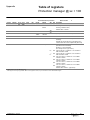
Contents
COMBT32EN – 04/2011
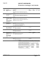
Communication architecture
3
Introduction
Circuit-breaker manager: @ xx
Chassis manager: @ xx + 50
Metering manager: @ xx + 200
Protection manager: @ xx + 100
3
5
6
7
10
Command interface
11
Operating principle
Send commands in shared mode
Send commands in protected mode
Remote configuration
11
12
13
17
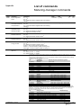
Access to the files
20
Introduction
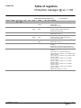
Event log of the circuit-breaker manager
Event log of the protection manager
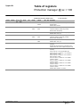
Event log of the metering manager
Maintenance event log of the protection manager
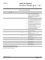
Maintenance event log of the metering manager
Min-Max event log of the metering manager
Wave Form Capture
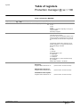
Fault Wave Form Capture
20
21
23
25
27
29
31
33
35
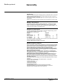
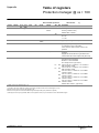
Modbus protocol
37
Generality
Modbus functions
37
38
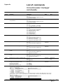
Appendix
41
Format
Trip/Alarm history
Trip/Alarm history
Table of registers
41
42
43
45
Structure of the table
Circuit-breaker manager @ xx
Chassis manager @ xx + 50
Metering manager @ xx + 200
Protection manager @ xx + 100
Communication profile @ xx
Circuit-breaker manager commands
Circuit-breaker manager commands
Metering-manager commands
Protection-manager commands
45
46
52
55
77
107
115
116
117
118
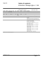
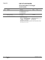
Examples of commands
119
Send commands in shared mode Simplified Open/Close
Send commands in protected mode
Remotely open the circuit breaker
Remotely close the circuit breaker
Synchronise the clocks
Remotely configure and set
Run remote Resets / Preset
Manage the event logs
Configure Analog pre-defined Alarm n°1: Over Current Phase A
Manage the Wave Form Capture
Manage the Fault Wave Form Capture
119
120
121
122
123
124
125
126
128
129
130
1
COMBT32EN – 04/2011
2
Communication
architecture
E71901A
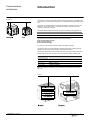
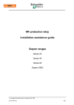
Introduction
Connection of a fixed circuit breaker requires one connection point on the RS485 bus
for the "device" communication module which is installed behind the Micrologic control
unit.
Connection of a withdrawable circuit breaker requires two connection points on the
RS485 bus, one for the "device" communication module and the second for the
"chassis" communication module.
The RS485 standard limits the number of physical connections per segment to 32
Maximum number of circuit breakers per RS485 segment
Fixed
31
Withdrawable
15
The "device" communication module contains three managers:
b the circuit-breaker manager
b the metering manager
b the protection manager.
The "chassis" communication module contains the chassis manager.
The division into four separate managers enhances the security of data exchange
between the supervision system and the circuit-breaker actuators.
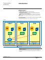
The manager addresses are automatically inferred from the @xx address entered on
the Micrologic control unit. By default, the circuit-breaker manager address is 47.
Addresses
@ xx
Circuit-breaker manager
@ xx + 50
Chassis manager
@ xx + 200
Metering manager
@ xx + 100
Protection manager
Note: For information on setting the control-unit address, see the installation manual for the
equipment.
E71902A
COMBT32EN – 04/2011
3
Communication
architecture
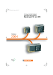
Introduction
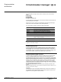
Manager architecture
b A manager contains:
v a table of registers that may be read-accessed only
v files such as the event log
v commands for functions such as write in the registers, turn the circuit
breaker ON or OFF, reset counters, etc
v Modbus functions used to remotely access the registers and the manger
files.
Note: The commands for the metering and protection managers are controlled by the circuitbreaker manager.
b A command interface in the circuit-breaker and chassis managers is used to
control the applications.
This interface monitors execution of the command and issues a report.
E71900A
Modbus functions
The device and chassis Modbus options operate in slave mode and enable a
Modbus master to access all the registers, files and applications contained in the
managers.
COMBT32EN – 04/2011
4
Communication
architecture
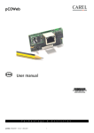
Circuit-breaker manager: @ xx
The circuit-breaker manager may be used to remotely monitor circuit-breaker
status:
b open (OFF)
b closed (ON)
b tripped (SDE)
b ready to close (PF), etc.
It is also possible to remotely open or close the circuit breaker if the MX and/or XF
communicating coils are installed.
Remote control (“Auto” mode) may be disabled by locally setting the Micrologic
control unit to Local control ("Manu" mode). See register 670
The circuit-breaker manager contains the registers listed below.
Register range
Description
515-543
Modbus configuration and identification
544-577
Diagnostics counters and Modbus password
603-624
Metering/protection manager event notification
650-670
Tripping cause and circuit-breaker status
671-715
Time-stamping of last status changes
718-740
Event log in the circuit-breaker manager (see the
section : Access to the files)
800
Communication profile activation
12000-12215
Communication profile
Note. More detailed information on these registers is presented in the section Appendix: Table
of registers: circuit-breaker -manager.
Communication profile
In order to optimize the number of Modbus request, a communication profile has
been implemented. The communication profile is located in the circuit-breaker
manager @xx. This communication profile contains information’s coming from the
circuit-breaker manager, the metering manager and the Protection manager. The
communication profile is defined in the register range: 12000-12215.
Simplified OPEN/CLOSE command
In order to simplify the application software to remotely open or close the circuitbreaker, a simplified OPEN/CLOSE command has been implemented. The
simplified OPEN/CLOSE command is located in the circuit-breaker manager @xx.
With the simplified OPEN/CLOSE command, it is not necessary to request the flag,
neither to enter in configuration mode, neither to read the control word. It is still
necessary to be in AUTO mode (see register 670). Furthermore, this simplified
OPEN/CLOSE command is password protected (default value=0000). In order to
change the password, it is mandatory to use the « magic box » and the associated
Micrologic utility RSU.(please consult us).
The simplified OPEN/CLOSE command is a share command (command code =
57400).
Note: More detailed information on this command is presented in the section Appendix: List of
command: circuit-breaker -manager.
.
WARNING:
Communication profile and simplified OPEN/CLOSE command are available only
with a Breaker Communication Module firmware version greater or equal to V2.0
(register 577 must be greater or equal to 02000)
COMBT32EN – 04/2011
5
Communication
architecture
Chassis manager: @ xx + 50
The chassis manager indicates the position of the device on the chassis:
b "connected" position
b "test" position
b "disconnected" position.
The chassis manager contains the registers listed below.
Register range
Description
515-543
Modbus configuration and identification
544-577
Diagnostics counters and Modbus password
661-664
Chassis status
679-715
Time-stamping of last status changes
Note: More detailed information on these registers is presented in the section Appendix: Table
of registers: chassis-manager.
.
COMBT32EN – 04/2011
6
Communication
architecture
Metering manager: @ xx + 200
The metering manager prepares the electrical values used to manage the lowvoltage distribution system.
Every second, the metering manager refreshes the "real-time" RMS measurements.
Using this data, it then calculates the demand and energy values, and stores the
minimum / maximum values recorded since the last reset.
Metering-manager operation depends on the Micrologic settings:
b type of neutral (internal, external, none)
b the normal direction for the flow of active power (this setting determines
the sign of the measured power).
b voltage-transformation ratio
b rated frequency.
The metering manager must be set independently of the protection manager to
determine:
b the calculation mode for the power (type of distribution system)
b the calculation mode for the power factor (IEEE, IEEE alt., IEC)
The metering manager contains the registers listed below.
Register range
Description
1000-1299
Real-time measurements
1300-1599
Minimum values for the real-time measurements from 1000 to
1299
1600-1899
Maximum values for the real-time measurements from 1000 to
1299
2000-2199
Energy
2200-2299
Demand values
3000-3299
Time stamping
3300-3999
Configuration of the metering manager
4000-4099
Reserved
4100-5699
Spectral components
5700-6899
Analog pre-defined alarm (1 to 53)
7100-7499
File Header/ status
(see the section : Access to the files)
Note: More detailed information on these registers is presented in the section Appendix: Table
of registers: metering-manager.
Registers 1000 to 1299: real-time measurements
The metering manager refreshes the real-time measurements every second.
Registers 1300 to 1599: minimum values of the real-time
measurements from 1000 to 1299
The minimum values for the real-time measurements may be accessed at the
registers of the real-time values + 300.
COMBT32EN – 04/2011
7
Communication
architecture
Metering manager: @ xx + 200
All the minimum values are stored in non volatile memory and may be reset to zero,
group by group according to the list below, by the command interface:
b RMS current
b current unbalance
b RMS voltage
b voltage unbalance
b frequency
b power
b power factor
b fundamental
b total harmonic distortion
b voltage crest factor
b current crest factor.
Note:
The minimum and maximum values of the real-time measurements are stored in the
memory. They may be reset to zero.
The maximum values of the demand measurements are time stamped and stored in
memory. They may be reset to zero.
Registers 1600 to 1899: maximum values of the real-time
measurements from 1000 to 1299
The maximum values for the real-time measurements may be accessed at the
registers of the real-time values + 600.
All the maximum values are stored in non volatile memory and may be reset to
zero, group by group according to the list below, by the command interface:
b RMS current
b current unbalance
b RMS voltage
b voltage unbalance
b frequency
b power
b power factor
b fundamental
b total harmonic distortion
b voltage crest factor
b current crest factor.
Registers 2000 to 2199: energy measurements
The energy counters may be:
b reset to zero
b preloaded with an initial value
using the reset applications via the command interface.
Registers 2200 to 2299: demand values
The demand values are refreshed every 15 seconds for sliding windows or at the
end of the time interval for block windows. When block windows are used, an
estimation of the value at the end of the time interval is calculated every 15
seconds.
COMBT32EN – 04/2011
8
Communication
architecture
Metering manager: @ xx + 200
Registers 3000 to 3299: time stamping
The time-stamping function becomes useful once the time and date have been set
on the Micrologic control unit, either locally or via the communication network.
If power to the Micrologic control unit is cut, the time and date must be set again.
With firmware release “logic 2002 AA” and above, the clock is powered by the
battery. So, it is no more necessary to set time and date after power comes off on
the Micrologic control unit.
If power to the communication option is cut, the time and date must be set again
The maximum drift of the Micrologic clock is approximately 0.36 seconds per day.
To avoid any significant drift, the clocks must be periodically synchronised via the
communication network.
Registers 3300 to 3999: configuration of the metering manager
The configuration registers may be read at all times. The registers may be modified
via the command interface in configuration mode.
Registers 4100 to 5699: spectral components
b RMS/phase of voltage harmonic
b RMS/phase of current harmonic.
Registers 6000 to 6899: Analog pre-defined Alarms (1 to 53)
The alarms registers may be read at all times. The registers may be modified via
the command interface in configuration mode. These alarms (available with
Micrologic H only) can be used to trigger Wave form Capture.
Registers 7100 to 7499: File header/Status
Event log configuration/characteristics and format of records for:
Wave Form Capture
(file n° 5)
Event log of the metering manager
(file n° 10)
Min-Max event log
(file n° 11)
Maintenance event log of the metering manager (file n° 12)
COMBT32EN – 04/2011
9
Communication
architecture
Protection manager:
@ xx + 100
The protection manager ensures the critical circuit-breaker functions. The Micrologic
control unit was designed to make this manager completely independent and thus
guarantee secure operation.
It does not use the measurements generated by the metering manager, but rather
calculates the protection-function inputs and outputs itself. This ensures extremely
fast reaction times.
The protection manager manages:
b The basic protection: the long-time (LT), short-time (ST), instantaneous and
ground-fault current protection functions
b The advanced protection: currents I max, I unbal, voltages U max, U min
and U unbal, frequency F max and F min, maximum reverse power Rp max,
phase rotation ΔΦ.
The protection manager controls:
b the automatic load shedding and reconnection functions, depending on
current and power
b the optional M2C and M6C contacts.
It is also possible to remotely access the protection manager. Remote access to the
protection manager may be enabled by locally setting the Micrologic control unit to
YES (remote access unlocked). See register 9800.
A local operator may disable all remote access to the protection manager by
opening the Micrologic plastic cover. It is also possible to limit access to certain
users by setting up a password on the Micrologic control unit.
A protection function intended to trip the circuit breaker cannot be modified if the
protective cover is closed, with or without the password.
The protection manager contains the registers listed below.
Register range
Description
8750-8753
Characteristics of the protection manager
8754-8803
Fine settings for the long-time, short-time, instantaneous,
ground-fault and earth-leakage protection functions
8833-8842
Measurements carried out by the protection manager
8843-8865
Status of the protection manager
9000-9599
Time stamping and trip/alarm history
9600-9628
Micrologic configuration
9629-9799
Advanced protection settings
9800-9899
Relay configuration (M2C/M6C)
9900-9924
Event log (see the section : Access to the files)
File N° 20
9932-9956
Maintenance event log (see the section : Access to the files)
File N° 12
9964-9989
Fault Wave form Capture (see the section : Access to the
files) File N° 22
Note: More detailed information on these registers is presented in the section Appendix: Table
of registers: protection manager.
.
COMBT32EN – 04/2011
10
Command interface
Operating principle
Write access to Micrologic data and control-unit options is monitored to inhibit
accidental operation and operation by unauthorised persons.
Commands sent to Micrologic control units are carried out via a command interface.
The command interface manages transmission and execution of the various
commands using the registers numbered from 7700 to 7729 that may be accessed
by the Modbus read and write functions.
The circuit-breaker manager supports the command interface for the commands
intended for the circuit-breaker, measurement and protection managers.
The chassis manager supports its own command interface.
Slave @ xx
[circuit-breaker manager]
Command interface 7700 to 7729
Commands intended for
the circuit-breaker manager
Slave @ xx+50
[chassis manager]
Command interface 7700 to 7729
Commands intended for the
chassis manager only
Commands intended for
the protection manager
Commands intended for
the metering manager
The command interface offers two command-management modes:
b Shared mode
This mode may be used to send up to 20 commands in series. It returns exclusively
the indications on command transmission via the Modbus protocol. This mode does
not return the result of command execution. Therefore, it is not recommended to
use the I/O scanning mode with Modbus TCP/IP protocol.
b Protected mode
This mode may be used to monitor execution of a command and to manage access
by a number of supervisors to a single circuit breaker. This is the case for the
Modbus multi-master architectures on Ethernet TCP/IP).
When a command is written, the command interface updates its registers with
information on command execution. It is necessary to wait until the command is
terminated before sending the next command. (Recommended time-out is 500
ms)
Furthermore, when the command is terminated, it is necessary to respect a delay
before sending the next command. (Recommended delay is 20 ms).
Access control is achieved by a flag reservation and freeing mechanism. In
protected mode, a command may be issued only after receiving a flag (and not after
releasing the flag).
Note: Certain commands may be accessed only in protected mode. See the section with the list
of commands to determine the possible command-management modes.
Command interface registers
register
address
scale
unit
format
interval
A/E
P/H
description
7699
nb of read/
reg. write
10
R/W
7700
-
-
INT
0.. 65535
A/E
P/H
command interface in shared
(1),
mode – commands
7715
7714
5
R
-
-
INT
0.. 65535
A/E
P/H
command interface in protected
(1)
mode – status
7720
7719
10
R/W
-
-
INT
0.. 65535
A/E
P/H
command interface in protected
(1),
mode – commands
7730
7729
100
R
-
-
INT
0.. 65535
A/E
P/H
command interface in protected
(1),
mode – return data
(1)
COMBT32EN – 04/2011
See the section “List of commands".
11
Command interface
Send commands in shared
mode
The shared mode uses the registers numbered 7700 to 7709 in the command
interface:
Command interface registers 7700 to 7709 may be read accessed. They are
used to send parameters and run execution of commands in shared mode.
Registers
Description
7700
Command number
7701
Parameter P1
7702
Parameter P2
7703
Parameter P3
7704
Parameter P4
7705
Parameter P5
7706
Parameter P6
7707
Parameter P7
7708
Parameter P8
7709
Parameter P9
See the list of commands that may be accessed in shared mode and the
corresponding parameters in the section with the list of commands for
Micrologic control units.
Proceed in the following manner to send a command in shared mode.
b Step 1. Parameters
Fill in the command parameters in registers 7701 to 7709
b Step 2. Write command
Write the command number to register 7700 to initiate execution.
It is possible to optimise data flow on the communication system by using function
16 in the Modbus protocol. In this case, the data may be written to registers 7700 to
7709 in a single step. The circuit-breaker communication option will automatically
put steps 1 and 2 in the correct order.
COMBT32EN – 04/2011
12
Command interface
Send commands in protected
mode
The protected mode uses the registers numbered 7715 to 7829 in the command
interface.
Command interface registers 7715 to 7719 may be read accessed only and
provide the indications required to use the protected mode (status).
Registers
Description
7715
Flag query
7716
Active Flag
7717
Number of the command being executed
7718
Number of the last command executed
(4)
7719
Result code of the last command executed
(1)
(2)
(3)
(4)
Note:
(1)
Register 7715 must be read-accessed to request an access flag to the command interface in
protected mode. The communication option returns 0 if the flag was already attributed during a
previous query and not returned (see the command table for information on return). Otherwise,
a random number is read, corresponding to the flag attributed. This number becomes the active
flag.
(2)
The active flag indicates to a supervisor the number of the flag with current access rights to
the command interface in protected mode. Only the supervisor that was attributed the given
number during a flag query has the right to use the command interface in protected mode. The
active flag returns to 0 if no command is sent for two minutes or if the user returns the flag (see
the command table for information on return).
(3)
The number of the command currently being executed remains set to 0 as long as no
command is sent to 7720. As soon as a command is sent, register 7717 indicates the number of
the command. It returns to 0 when command execution is terminated.
(4)
When command execution is terminated, register 7718 receives the number of the command
and register 7719 indicates the result code. The contents of registers 7718 and 7719 are not
modified until the next command has been completely executed.)
Register 7719: Command result codes table
Result codes
COMBT32EN – 04/2011
Description of register 7719
0
Command successfully executed.
10
Command not executed, the necessary resources are not
available or the option is not installed. or remote access = NO
11
Command not executed, a local user is using the resources.
12
Command not executed, the portable test kit is using the local
resources.
14
Command not executed, the resources are being used by a
remote user.
15
Invalid record size.
16
Illegal file command.
17
Insufficient memory.
42
Invalid file number.
81
Command not defined.
82
Command parameters not set or invalid.
107
Invalid record number.
125
Invalid number of records.
200
Protected mode not active.
201
End of time delay. Command not executed.
202
Invalid password. Command not executed.
204
Invalid Command ; enter configuration mode while already in
configuration mode; exit configuration mode while not in
configuration mode
13
Command interface
Send commands in protected
mode
Command interface registers 7720 to 7729 may be read accessed. They are
used to send parameters and run execution of commands in protected mode.
Registers
Description
7720
Command number
7721
Parameter P1
7722
Parameter P2
7723
Parameter P3
7724
Parameter P4
7725
Parameter P5
7726
Parameter P6
7727
Parameter P7
7728
Parameter P8
7729
Parameter P9
See the list of commands that may be accessed in protected mode and the
corresponding parameters in the section with the list of commands for
Micrologic control units.
Command interface registers 7730 to 7829 may be read accessed. They are
used as a buffer for the returned data.
.
COMBT32EN – 04/2011
14
Command interface
Send commands in protected
mode
Proceed as follows to send a command in protected mode.
b Step 1: Request the flag
Read register 7715 to request the flag required to access the protected mode.
If the register returns 0, another user currently has the access rights and it is
necessary to wait until that user returns the flag. It is possible, however, that you
already took the flag for another command and did not return it.
E.g. if you wished to sequence sending of a series of commands.
It is possible to check if you have the rights by reading the active flag at register
7716. In this case, even if you read 0 at 7715 when you made the request, it is
possible to send the commands.
b Step 2: Fill in parameters
Fill in the command parameters (P1 to P9) in registers 7721 to 7729.
b Step 3: Write command
Write the command number to register 7720 to initiate execution.
b Step 4: Wait for command being executed
Wait until the command is fully terminated, by reading registers 7717 and
7718.
(Recommended time-out = 500 ms)
b Step 5: Check Result code
Check the result code for the command by reading register 7719.
b Step 6: Send New command
Send new commands in protected mode by starting with step 2 or go on to
step 7.
(Recommended delay between command fully terminated and new command = 20
ms)
b Step 7: Release the flag
Return the flag to free the protected mode. See the command table for
information on returning the flag.
COMBT32EN – 04/2011
15
Command interface
Send commands in protected
mode
Optimise sending of commands
It is possible to optimise data flow on the communication system by using function
16 in the Modbus protocol. In this case, the data may be written to registers 7720 to
7729 in a single step. The command interface will automatically put steps 2 and 3 in
the correct order.
Caution:
It is advised not to use function 23 to optimise steps 1, 2 and 3, because this
function does not check access rights to protected mode before sending the
command. This may cause problems for another supervisor who current has the
access rights.
Most of the commands that may be used to remotely control the circuit breaker
implement two steps, namely the request for the flag (step 1) and return of the flag
(step 7).
This mechanism makes it possible for a number of supervisors to issue commands,
on the condition that the two steps are implemented.
Using this procedure, you take and return the flag for each of the commands to be
issued. In this case, the possible degree of parallelism between the various
supervisors is increased, but at the cost of more traffic on the communication
system.
If you have a number of commands to send, optimise the mechanism by sending all
the commands between the two steps, i.e. request the flag, send all the commands
in one shot and then return the flag. In this case, you occupy the command interface
for a longer time, but traffic on the communication system is optimised.
COMBT32EN – 04/2011
16
Command interface
Detailed information on the registers is presented
in the Appendix containing the tables of registers.
Remote configuration
A number of simple concepts must be clear in order to remotely configure the circuit
breaker successfully.
b Configuration is carried out via the configuration registers (R/W).
The configuration registers for all the managers (circuit breaker, chassis, metering
and protection) may be read accessed in the table of registers.
The only way to remotely modify a configuration is to modify the contents of the
configuration registers.
b The configuration registers (R/W) may be write accessed in configuration
mode only.
To modify the configuration registers, it is necessary to remove the register writeprotect function by running the command required to enter in configuration mode,
via the command interface. Once in configuration mode, it is possible to write
access the configuration registers and you may modify one or more configuration
registers using the standard Modbus write functions.
Circuit-breaker manager
@ xx
Register range
Configuration registers
534-543
Identification of the Breaker Communication Module
Chassis manager
Register range
534-543
@ xx + 50
Configuration registers
Identification of the Chassis Communication Module
Metering manager
Register range
3303-3355
@ xx + 200
Configuration registers
Configuration of the metering manager
6000-6011
Configuration of Analog pre-defined Alarm 1
6012 to 6635
Configuration of Analog pre-defined Alarm 2 to 53
Protection manager
Register range
8753-8803
@ xx + 100
Configuration registers
Fine adjustments for the basic protection
9604-9618
Configuration of the protection manager
9629-9798
Settings for the advanced protections
9800-9846
Configuration of the output relays (M2C/M6C)
Specific conditions must be met to enter the configuration mode.
COMBT32EN – 04/2011
17
Command interface
Remote configuration
Consult the list of commands for details
on the check words.
Remote access is not possible if local configuration is
underway and vice-versa
When a local user is in the process of locally modifying the configuration of
Micrologic or of its options, it is not possible to start a remote-configuration
sequence.
Micrologic considers that a local user is in the process of modifying the
configuration when a parameter field is displayed in reverse video or as soon as the
Micrologic plastic cover is opened.
Access to configuration mode is subject to different
restrictions depending on the manager
Access to configuration mode for the protection manager requires the remoteaccess code that was programmed on the front panel of the Micrologic control unit.
This code (default value = 0000) may be obtained only via the setting screen on the
Micrologic control unit itself. What is more, it is possible to access the configuration
mode for the protection manager only if the Micrologic control unit has been set to
authorise remote access. This setting must be made manually via the front panel of
the Micrologic control unit. It is possible to consult the protection-manager register
9800 to check the status of this parameter. Then you can access to the
configuration mode for the protection manager by using the command In_pCfg.
Access to configuration mode for the circuit-breaker and metering managers
requires a control word that must first be read in the table of registers. Register 553
is the control word for the circuit-breaker, register 3300 is the control word for the
metering manager. Then you can access to the configuration mode by using the
command In_mCfg for the metering manager or by using the command
In_CommCfg for the circuit-breaker manager.
This two-step operation is intended to avoid inadvertent access to the configuration
mode.
The access commands for configuration mode implement the protected mode and
systematically inform on the command result.
New configurations are always checked before being
accepted
When writing in the configuration registers, the Modbus write functions are
accepted, even if the written value exceeds the limits presented in the tables of
registers that should be consulted first.
To assist in configuring the protection functions, Micrologic provides access to a set
of registers that list the minimum and maximum permissible values for the various
protection settings
All the configuration data entered are checked before they enter into effect. This
check is run when you exit configuration mode, using the commands Out_pCfg for
the protection manager, Out_mCfg for the metering manager or Out_CommCfg for
the circuit-breaker manager.
If one of the configuration settings is incorrect, all the new configuration data are
rejected. The system indicates why the data are rejected via the result returned for
the command used to exit the configuration mode. The protection manager
indicates the first ten faulty configuration registers. See the information on
command Out_pCfg for further details.
The new configuration data take effect only on exiting
configuration mode
The new configuration data take effect only on exiting configuration mode so that
the data can be checked. I.e., it is when the Out_pCfg, Out_mCfg or Out_CommCfg
command has been successfully run that the new configuration settings become
active.
COMBT32EN – 04/2011
18
Command interface
Remote configuration
Example of a remote parameter-setting sequence
Below are the steps that must be followed to modify the long-time (LT) current
setting.
b Step 1
Check that remote access is authorised by reading register 9800 at address @+100
[protection manager].
b Step 2
Make sure you have the remote-access code, noted on the "Local / Remote" screen
in the "COM setup" menu of Micrologic (default value = 0000).
b Step 3
Enter configuration mode for the protection manager, using the In_pCfg command.
See the "Examples of commands" appendix.
b Step 4
Enter the new setting in registers 8753 to 8803, at the address @+100 [protection
manager].
Make sure these new settings are below the value set by the rotary switch.
b Step 5
Exit configuration mode for the protection manager, using the Out_pCfg command,
and check first for an error code returned by the command interface, then the
parameters returned by Out_pCfg in registers 7730 to 7739 of the circuit-breaker
command interface.
b Step 6
Read the contents of the registers 8756 and 8757. The settings should be those
entered, if step 5 did not return an error.
COMBT32EN – 04/2011
19
Access to the files
Introduction
Micrologic stores events and wave form in different files. These files may be read
with the command interface: ReadFileX_RecY. The requested recording may be
read starting in registers 7730. See the section Appendix: Examples of commands.
A file is made up of records. All records in a file have the same structure and size.
Each record, with a maximum of 100 is made up of a number of registers.
Each file is linked to a descriptor. The descriptor is made up of a read zone for file
configuration (Header) and for file characteristics (Status). Descriptors are updated
each time new data is added to the file.
The file configuration (Header) gives information about size of file and records.
The file Characteristic (Status) gives information about record numbers. The file
characteristics (Status) makes available to the supervisor two sequence registers
that indicate the first and last events recorded in the file. They enable the supervisor
to determine whether certain events were deleted before they could be read. The
sequence number for the last event increments from 1 to 8000 each time a new
event is recorded. When the file is full (maximum of 100), the new events overwrite
the oldest events. The sequence number for the last event continues to increment
normally. When the oldest event is overwritten, the sequence number for the first
event also increments.
When the sequence number reaches 8000, the next sequence number will be one.
Event log
b The event log of the circuit-breaker manager Micrologic A/E/P/H
The system stores the events that concern circuit-breaker control (e.g. opening or
closing of the contacts) in the file N° 30. This file is made up of 100 records; each
record is made up of 5 registers. This file is reset in case of 24 VDC power loss on
the Breaker Communication Module or change of the communication parameter
4W/2W +ULP.
b The event log of the protection manager
Micrologic P/H
The system stores the events that concern the protection manager (trips, alarms) in
the file N° 20. .This file is made up of 100 records; each record is made up of 9
registers.
b The event log of the metering manager
Micrologic H
The system stores the events that concern the metering manager (Analog
Pre-defined alarms 1 to 53) in the file N° 10. This file is made up of 100 records;
each record is made up of 9 registers.
b The Maintenance event log of the protection manager
Micrologic H
The system stores the events that concern the maintenance protection manager
(power-up, M6C relays, Max peak fault current, …) in the file N° 21. .This file is
made up of 20 records; each record is made up of 6 registers.
This maintenance event log has been implemented as well on Micrologic P with
firmware Plogic2002AA and above.
b The Maintenance event log of the metering manager
Micrologic H
The system stores the events that concern the maintenance metering manager
(counter reset …) in the file N° 12. .This file is made up of 20 records; each record
is made up of 6 registers.
b The min-MAX event log of the metering manager
Micrologic H
The system stores the events that concern the metering manager (minimum and
Max values for the Real Time measurements 1000 to 1136) in the file N° 11. .This
file is made up of 136 records; each record is made up of 8 registers.
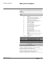
Wave Form Capture
b The WFC in the metering manager
Micrologic H
The system stores the variables Va, Vb, Vc, Ia, Ib, Ic, Ineutral during 4 cycles (64
points per cycles) in the file N° 5.
The capture is triggered:
v manually (user request) by using the command “ Forcelog “
(See the section Appendix : List of commands in the metering manager)
v automatically attached to Pre-defined analog alarms (1 to 53) by setting to 1 the
log action.
(See register 6010 for alarm N° 1, register 6634 for alarm N° 53)
b The Fault WFC in the protection manager
Micrologic H
The system stores the variables Va, Vb, Vc, Ia, Ib, Ic, Ineutral during 12 cycles (16
points per cycles) in the file N° 22.
The capture is triggered:
automatically attached to alarms (1000 to 1030) .by setting to 1 the log action
(See register 8762 for alarm N° 1000, register 9797 for alarm N° 1030)
COMBT32EN – 04/2011
20
Access to the files
Event log of the circuit-breaker
manager
Descriptor of the event log in the circuit-breaker manager
b Event log configuration (Header)
register
address
scale
unit
format
interval
A/E
P/H
description
717
nb of read/
reg. write
1
R
718
-
-
INT
0xFFFF
A/E
P/H
File status :0xFFFF= file enabled
always equal to : 0xFFFF
719
718
1
R
-
-
INT
30
A/E
P/H
type of file: event log of the circuit-breaker
manager
always equal to : 30
720
719
1
R
-
-
INT
0xFFFF
A/E
P/H
File allocation : 0xFFFF= file allocated
always equal to : 0xFFFF
721
720
1
R
x1
register
INT
5
A/E
P/H
Size of records in register
always equal to : 5
722
721
1
R
-
-
INT
0
A/E
P/H
File filling mode : 0 = circular
always equal to : 0
b Event log characteristics (status)
register
address
nb of read/
reg. write
scale
unit
format
interval
A/E
P/H
734
733
1
R
x1
rec.
INT
100
A/E
P/H Size of file in records
always equal to 100
735
734
1
R
x1
register
INT
5
A/E
P/H size of a record in registers
always equal to 5
737
736
1
R
x1
rec.
INT
0..100
A/E
P/H number of records in the file
0 = no record in the file
738
737
1
R
x1
rec.
INT
0..8000
A/E
P/H sequence number of first record in the file (the
oldest)
0 = no record in the file
739
738
1
R
x1
rec.
INT
0..8000
A/E
P/H sequence number of last record in the file (the
most recent)
0: no record in the file
740
739
3
R
-
-
DATE
-
COMBT32EN – 04/2011
description
P/H date the last file was reset
21
Access to the files
Event log of the circuit-breaker
manager
Format of records in the event log of the circuit-breaker
manager
Registers
1-4
Description
Event date, in the XDATE format
(see the section Appendix: Formats)
5
Event number (See below)
Events in the event log of the circuit-breaker manager
Event number
1
COMBT32EN – 04/2011
Description
RESET or system energized
2
Configuration data stored in the chassis manager
3
Spring charged
4
Circuit breaker opened (O)
5
Circuit breaker closed (F)
6
Circuit breaker tripped (SD)
7
Circuit breaker fault tripped (SDE)
8
Reserved
9
Reserved
10
Closing command input remotely (AUTO) (XF)
11
Opening command input remotely (AUTO) (MX)
12
Modification of Modbus configuration (address,
baud rate, parity)
13
Event log reset
14
Clock update input locally accepted
15
Clock update input locally rejected
(synchronization by the supervisor)
22
Access to the files
Event log of the protection
manager
Descriptor of the event log in the protection manager
b Event log configuration (Header)
register
address
nb of read/
reg. write
scale
unit
format
interval
A/E
P/H
description
9900
9899
1
R/W
-
-
INT
{0x0000,
0xFFFF}
P/H file status
0xFFFF: file enabled
0: file disabled
Default value: 0xFFFF
9901
9900
1
R
-
-
INT
20
P/H type of file: protection-manager event log
always equal to : 20
9902
9901
1
R
x1
rec.
INT
100
P/H size of file in records
always equal to : 100
9903
9902
1
R
x1
register
INT
9
P/H size of a record in registers
always equal to : 9 registers per record
9904
9903
1
R
-
-
INT
0
P/H file filling mode 0: circular
always equal to 0
b Event-log characteristics (Status)
register
address
nb of read/
reg. write
scale
unit
format
interval
9916
9915
1
R
x1
rec.
INT
100
P/H size of file in records
always equal to 100
9917
9916
1
R
x1
Registe
r
INT
9
P/H size of a record in registers: always equal to 9
9918
9917
1
R
x1
-
INT
0,10,20,30,
250,253,
254,255,
0xFF00,
0xFE00,
OxFD00,
OxFC00
P/H 0: file OK
10: record size smaller than expected
20: record size larger than expected
30: insufficient memory
250: internal error
253: corrupted allocation table
254: configuration zero
255: invalid configuration
0xFF00: cannot allocate file
0xFE00: file not supported
0xFD00: invalid record number
0xFC00: invalid file number
9919
9918
1
R
x1
rec.
INT
0..100
P/H number of records in the file
0: no record in the file
9920
9919
1
R
x1
rec.
INT
0..8000
P/H sequence number of first record in the file (the
oldest)
0: no record in the file
9921
9920
1
R
x1
rec.
INT
0..8000
P/H sequence number of last record in the file (the
most recent).
0: no record in the file
9922
9921
3
R
-
-
DATE
cfformat
P/H date the last file was reset
Default value: 0x8000 0x8000 0x8000
COMBT32EN – 04/2011
A/E
P/H
description
23
Access to the files
Event log of the protection
manager
Format of records in the event log of the protection manager
Registers
Description
1-4
Event date, in the XDATE format
(see the section Appendix: Formats)
5
Event number (see below)
6
Event characteristics
7
Type of event
8
Logging bitmap associated to the Alarm
9
(1)
(2)
Action bitmap associated to the Alarm
(3)
(3)
Note.
(1)
For alarms 1000 to 1004, the data is the value of the fault current interrupted by the circuit
breaker. For all other events, this value is forced to 32768.
(2)
Bits 0 to 7
The value 1 indicates an alarm of the "Over" type.
The value 2 indicates an alarm of the "Under" type.
The value 3 indicates an alarm of the "Minimum" type.
The value 4 indicates an alarm of the "Maximum" type.
The value 5 indicates an alarm of the "Assorted" type.
(2)
Bits 8 to 11
The value 1 indicates the start of an alarm.
The value 2 indicates the end of an alarm
(2)
Bits 12 to 15
Alarms 1100 to 1106 are priority 3. For the other alarms, the value contained in these four bits
represents the priority linked to the event (if applicable and depending on the alarm
configuration.
(3)
Registers 8 and 9 are a copy of the alarm-configuration registers at the moment the event
occurred. They depend entirely on the user configurations. For the events 1100 to 1106, these
registers are forced to 32768.
Events in the event log of the protection manager
Event number
Description
1000 to 1015
Basic protection
1016 to 1031
Advanced protection
1100 to 1115
Digital alarms
(1)
(1)
(1)
(1) See description of the "Alarm numbers" in the section Appendix: Trip/Alarm History
COMBT32EN – 04/2011
24
Access to the files
Event log of the metering
manager
Descriptor of the event log in the metering manager
b Event log configuration (Header)
register
address
nb of read/
reg. write
scale
unit
format
interval
7164
7163
1
R/W
-
-
INT
7165
7164
1
R
-
-
7166
7165
1
R
x1
7167
7166
1
R
7168
7167
1
R
A/E
P/H
description
{0x0000,
0xFFFF}
H
log status
0xFFFF: file enabled
0: file disabled
Default value: 0xFFFF
INT
10
H
type of file: metering-manager event log
Default value: 10
rec.
INT
100
H
size of file in records
Default value: 100 records per file
x1
register
INT
9
H
size of a record in registers
Default value: 9 registers per record
-
-
INT
0
H
file filling mode : 0 = circular
always equal to 0
b Event-log characteristics (Status)
register
address
nb of read/
reg. write
scale
unit
format
interval
7180
7179
1
R
x1
rec.
INT
7181
7180
1
R
x1
register
7182
7181
1
R
x1
7183
7182
1
R
7184
7183
1
7185
7184
7186
7185
P/H
description
100
H
size of file in records :100
always equal to 100
INT
9
H
size of a record in registers: always equal to 9
-
INT
0,10,20,30,
250,253,
254,255,
0xFF00,
0xFE00,
OxFD00,
OxFC00
H
0: file OK
10: record size smaller than expected
20: record size larger than expected
30: insufficient memory
250: internal error
253: corrupted allocation table
254: configuration zero
255: invalid configuration
0xFF00: cannot allocate file
0xFE00: file not supported
0xFD00: invalid record number
0xFC00: invalid file number
x1
rec.
INT
0..100
H
number of records in the file
0: no record in the file
R
x1
rec.
INT
0..8000
H
sequence number of first record in the file (the
oldest)
0: no record in the file
1
R
x1
rec.
INT
0..8000
H
sequence number of last record in the file (the
most recent)
0: no record in the file
3
R
-
-
DATE
cfformat
H
date the last file was reset
Default value: 0x8000 0x8000 0x8000
COMBT32EN – 04/2011
A/E
25
Access to the files
Event log of the metering
manager
Format of records in the event log of the metering manager
Registers
Description
1-3
Event date, in the XDATE format
(see the section Appendix: Formats)
4
Reserved
5
Event number (see below)
6
Extreme value
7
Type of event
8
Logging bitmap associated to the Alarm
9
Action bitmap associated to the Alarm
(2)
(3)
(3)
Note.
(2)
Bits 0 to 7
The value 0 indicates an alarm of the "Over" type.
The value 1 indicates an alarm of the "Under" type.
The value 2 indicates an alarm of the "Equal to” type.
The value 3 indicates an alarm of the "Different from" type.
The value 5 is used for all other alarms
(2)
Bits 8 to 11
The value 1 indicates the start of an alarm.
The value 2 indicates the end of an alarm.
(2)
Bits 12 to 15
The value contained in these four bits represents the priority linked to the event (if applicable
and depending on the alarm configuration.
(3)
Registers 8 and 9 are a copy of the alarm-configuration registers at the moment the event
occurred. They depend entirely on the user configurations.
Events in the event log of the metering manager
Event number
Description
1 to 53
Analog Pre-defined alarms
(1)
See the "Analog pre-defined alarms"1 to 53 in the section: Appendix Table of registers 6000
to 6624
COMBT32EN – 04/2011
26
Access to the files
Maintenance event log of the
protection manager
Descriptor of the Maintenance event log in the protection
manager
b Event log configuration (Header)
register
address
nb of read/
reg. write
scale
unit
format
interval
9932
9931
1
R/W
-
-
INT
9933
9932
1
R
-
-
9934
9933
1
R
x1
9935
9934
1
R
9936
9935
1
R
A/E
P/H
description
0xFFFF
H
File status
0xFFFF: file enabled
always equal to: 0xFFFF
INT
21
H
type of file: Maintenance protection-manager
event log
always equal to: 21
rec.
INT
20
H
size of file in records
always equal to 20 records per file
x1
register
INT
6
H
size of a record in registers
always equal to 6 registers per record
-
-
INT
1
H
log filling mode :1 = inhibition is full
always equal to 1
b Event-log characteristics (Status)
register
address
nb of read/
reg. write
scale
unit
format
interval
9948
9947
1
R
x1
rec.
INT
9949
9948
1
R
x1
register
9950
9949
1
R
x1
9951
9950
1
R
9952
9951
1
9953
9952
9954
9953
P/H
description
20
H
size of file in records : 20
size always equal to 20
INT
6
H
size of a record in registers: always equal to 6
-
INT
0,10,20,30,
250,253,
254,255,
0xFF00,
0xFE00,
OxFD00,
OxFC00
H
0: file OK
10: record size smaller than expected
20: record size larger than expected
30: insufficient memory
250: internal error
253: corrupted allocation table
254: configuration zero
255: invalid configuration
0xFF00: cannot allocate file
0xFE00: file not supported
0xFD00: invalid record number
0xFC00: invalid file number
x1
rec.
INT
20
H
number of records in the file
Always Equal to 20
R
x1
rec.
INT
1
H
sequence number of first record in the file
Always Equal to 1
1
R
x1
rec.
INT
20
H
sequence number of last record in the file
Always Equal to 20
3
R
-
-
DATE
cfformat
H
date the last file was reset
Default value: 0x8000 0x8000 0x8000
COMBT32EN – 04/2011
A/E
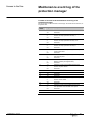
27
Access to the files
Maintenance event log of the
protection manager
Formats of records in the maintenance event log of the
protection manager
This file consists of a fixed number of records (20). All records are of similar size, i.e
6 registers wide.
COMBT32EN – 04/2011
Record
number
Registers
Description
1
1-3
4-6
Last Power Loss (XDATE Format)
Reserved
2
1-3
4
5-6
Date/time of last counter reset (DATE Format)
Number of output operations for relay 1
Reserved
3 to 6
1-3
4
5-6
Date/time of last counter reset (DATE Format)
Number of output operations for relay 3 to 6
Reserved
7
1-3
4
5-6
Date/time of last counter reset (DATE Format)
Number of output operations for relay 6
Reserved
8
1-3
4
5-6
Date/time of last record updated (DATE Format)
Worst contact wear
Reserved
9
1-3
4
5-6
Date/time of last record updated (DATE Format)
Max reverse power
Reserved
10
1-3
4
5-6
Date/time of last record updated (DATE Format)
Battery indicator (see register 8843)
Reserved
11
1-3
1
5-6
Date/time of last record updated (DATE Format)
Number of power losses
Reserved
12
1-6
Reserved
13
1-6
Reserved
14
1-6
Reserved
15
1-6
Reserved
16
1-3
4
5-6
Date/time of last record updated (DATE Format)
Number of Max resets
Reserved
17
1-6
Reserved
18
1-3
4
5-6
Date/time of last record updated (DATE Format)
Max peak fault current breaker ever opened
Reserved
19
1-6
Reserved
20
1-6
Reserved
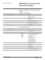
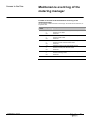
28
Access to the files
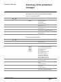
Maintenance event log of the
metering manager
Descriptor of the Maintenance event log in the metering
manager
b Event log configuration (Header)
register
address
nb of read/
reg. write
scale
unit
format
interval
7228
7227
1
R/W
-
-
INT
7229
7228
1
R
-
-
7230
7229
1
R
x1
7231
7230
1
R
7232
7231
1
R
register
address
7244
A/E
P/H
description
0xFFFF
H
File status
0xFFFF: file enabled
always equal to 0xFFFF
INT
12
H
type of file: Maintenance metering-manager event
log
always equal to: 12
rec.
INT
20
H
size of file in number of records
always equal to 20 records per file
x1
register
INT
6
H
size of a record in number of registers
always equal to 6 registers per record
-
-
INT
1
H
log filling mode :1= disabled if log is full
always equal to 1
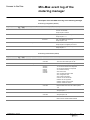
nb of read/
reg. write
scale
unit
format
interval
7243
1
R
x1
rec.
INT
7245
7244
1
R
x1
register
7246
7245
1
R
x1
7247
7246
1
R
7248
7247
1
7249
7248
7250
7249
b Event-log characteristics (Status)
P/H
description
20
H
size of file in records:20
always equal to 20
INT
6
H
size of a record in registers: always equal to 6
-
INT
0,10,20,30,
250,253,
254,255,
0xFF00,
0xFE00,
OxFD00,
OxFC00
H
0: file OK
10: record size smaller than expected
20: record size larger than expected
30: insufficient memory
250: internal error
253: corrupted allocation table
254: configuration zero
255: invalid configuration
0xFF00: cannot allocate file
0xFE00: file not supported
0xFD00: invalid record number
0xFC00: invalid file number
x1
rec.
INT
20
H
number of records in the file
Always Equal to 20
R
x1
rec.
INT
1
H
sequence number of first record in the file
Always Equal to 1
1
R
x1
rec.
INT
20
H
sequence number of last record in the file
Always Equal to 20
3
R
-
-
DATE
cfformat
H
date the last file was reset
Default value: 0x8000 0x8000 0x8000
COMBT32EN – 04/2011
A/E
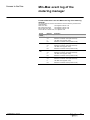
29
Access to the files
Maintenance event log of the
metering manager
Formats of records in the maintenance event log of the
metering manager
This file consists of a fixed number of records (20). All records are of similar size, i.e
6 registers wide.
COMBT32EN – 04/2011
Record
number
Registers
Description
1
1-3
4
5-6
Date/time of last counter reset (DATE Format)
Number of min resets
Reserved
2
1-3
4
5-6
Date/time of last counter reset (DATE Format)
Number of Max resets
Reserved
3
1-3
4
5-6
Date/time of last counter reset (DATE Format)
Number of Peak current Demand resets
Reserved
4
1-3
4
5-6
Date/time of last counter reset (DATE Format)
Number of Peak power demand resets
Reserved
5
1-3
4
5-6
Date/time of last counter reset (DATE Format)
Number of Energy resets
Reserved
6 to 20
1-6
Reserved
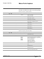
30
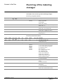
Access to the files
Min-Max event log of the
metering manager
Descriptor of the min-Max event log in the metering manager
b Event log configuration (Header)
register
address
nb of read/
reg. write
scale
unit
format
interval
7196
7195
1
R/W
-
-
INT
7197
7196
1
R
-
-
7198
7197
1
R
x1
7199
7198
1
R
7200
7199
1
R
A/E
P/H
description
0xFFFF
H
File status
0xFFFF: file enabled
always equal to 0xFFFF
INT
11
H
type of file: Min/Max event log = 11
always equal to: 11
rec.
INT
Real Time
zone size
H
size of file in number of records. identical to the
size of the MM Real Time zone.
always equal to 136
x1
register
INT
8
H
size of records in number of registers
always equal to 8 registers per record
-
-
INT
1
H
log filling mode 1: disabled if log is full
always equal to 1
b Event-log characteristics (Status)
register
address
nb of read/
reg. write
scale
unit
format
interval
7212
7211
1
x1
rec.
INT
Real Time
zone size
R
A/E
P/H
description
H
size of file in records: size always equal to Real
Time zone size Value equal to 136
7213
7212
1
R
x1
register
INT
8
H
size of a record in registers: always equal to 8
7214
7213
1
R
x1
-
INT
0,10,20,30,
250,253,
254,255,
0xFF00,
0xFE00,
OxFD00,
OxFC00
H
0: file OK
10: record size smaller than expected
20: record size larger than expected
30: insufficient memory
250: internal error
253: corrupted allocation table
254: configuration zero
255: invalid configuration
0xFF00: cannot allocate file
0xFE00: file not supported
0xFD00: invalid record number
0xFC00: invalid file number
7215
7214
1
R
x1
rec.
INT
Real Time
zone size
H
Actual number of records in the file. Always
Equal to Real Time zone size. Value equal to
136
7216
7215
1
R
x1
rec.
INT
1
H
number of first record present
Always Equal to 1
7217
7216
1
R
x1
rec.
INT
Real Time
zone size
H
number of last record present
Always Equal to 20
7218
7217
3
R
-
-
DATE
cfformat
H
date the last file was reset
Default value: 0x8000 0x8000 0x8000
COMBT32EN – 04/2011
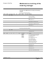
31
Access to the files
Min-Max event log of the
metering manager
Format of Records in the min-Max event log of the metering
manager
This file contains the minimum and Maximum values reached by the Real Time
measurements.
Real Time value:
See registers 1000 to 1135
Min of Real Time value:
See registers 1300 to 1435
Max of Real Time value:
See registers 1600 to 1735
All records are of similar size, i.e. 8 registers wide.
COMBT32EN – 04/2011
Record
number
Registers
Description
1
1
2-4
5
6-8
Last Min Value (register 1300)
Date/time of last Min Value (DATE Format)
Last Max Value (register 1600)
Date/time of last Max Value (DATE Format)
2
1
2-4
5
6-8
Last Min Value (register 1301)
Date/time of last Min Value (DATE Format)
Last Max Value (register 1601)
Date/time of last Max Value (DATE Format)
x (3 to
135)
1
2-4
5
6-8
Last Min Value (register 130x)
Date/time of last Min Value (DATE Format)
Last Max Value (register 160x)
Date/time of last Max Value (DATE Format)
136
1
2-4
5
6-8
Last Min Value (register 1435)
Date/time of last Min Value (DATE Format)
Last Max Value (register 1735)
Date/time of last Max Value (DATE Format)
32
Access to the files
Wave Form Capture
Descriptor of the Wave Form Capture in the metering manager
b Wave Form Capture configuration (Header)
register
address
nb of read/
reg. write
scale
unit
format
interval
7132
7131
1
R/W
-
-
INT
7133
7132
1
R
-
-
7134
7133
1
R
x1
7135
7134
1
R
7136
7135
1
7137
A/E
P/H
description
{0x0000,
0xFFFF}
H
File status :0xFFFF = file enabled
0x0000 = file disabled
Default value: 0xFFFF
INT
5
H
type of file: Wave Form Capture
always equal to: 5 (WFC)
rec.
INT
29
H
size of file in number records = 29
always equal to 29 records/file
x1
register
INT
64
H
size of records in number of registers
always equal to: 64 registers per record
R
-
-
INT
{0,1}
H
File filling mode : 1: disabled if log is full. 0: circular.
Default value: 0
7136
R
1
segment
INT
1
H
Number of 4 cycle segments
Always equal to 1
7138
7137
R
1
Cycle
INT
2
H
Number of cycle before capture
always equal to 2
7139
7138
R
1
points
INT
64
H
Number of points per cycle
always equal to 64
b Wave Form Capture characteristics (Status)
register
address
nb of read/
reg. write
scale
unit
format
interval
7148
7147
1
R
x1
rec.
INT
7149
7148
1
R
x1
register
7150
7149
1
R
x1
7151
7150
1
R
7152
7151
1
7153
7152
7154
7153
P/H
description
{0,29}
H
size of file in records
either equal to 0 or 29
INT
64
H
size of a record in registers: always equal to 64
-
INT
0,10,20,30,
250,253,
254,255,
0xFF00,
0xFE00,
OxFD00,
OxFC00
H
0: file OK. 10: record size smaller than expected. 20:
record size larger than expected. 30: insufficient
memory. 250: internal error. 253: corrupted allocation
table. 254: configuration zero
255: invalid configuration
0xFF00: cannot allocate file
0xFE00: file not supported
0xFD00: invalid record number
0xFC00: invalid file number
x1
rec.
INT
{0,29}
H
Actual number of records in the file. either equal to 0
or 29
R
x1
rec.
INT
{0,1}
H
number of first record present
either equal to 0 or 1
1
R
x1
rec.
INT
{0,29}
H
number of last record present
either equal to 0 or 29
3
R
-
-
DATE
cfformat
H
date the last file was reset
Default value: 0x8000 0x8000 0x8000
COMBT32EN – 04/2011
A/E
33
Access to the files
Wave Form Capture
Format of records in the Wave Form Capture of the metering
manager
This file consists of a fixed number of records (29). All records are of similar size, i.e
64 registers wide.
Record
number
Registers
Description
1
1-4
5-11
12
Extended Date/time
Reserved
Id of WFC trigger (analog pre-defined alarm 1 to 53)
Available with firmware HLogic2005AF
System type :31, 40 or 41 (See register 3314)
Breaker nominal current in Amps
Voltage multiplier for phase A (format is SFIXPT)
Voltage Offset for phase A (format is INT)
Same as 15, for phase B
Same as 16, for phase B
Same as 15, for phase C
Same as 16, for phase C
Current multiplier for phase A (format is SFIXPT)
Current Offset for phase A (format is INT)
Same as 21, for phase B
Same as 22, for phase B
Same as 21, for phase C
Same as 22, for phase C
Current multiplier for Neutral (format is SFIXPT)
Same as 22, for Neutral
Scaling factor used for SFIXPT math on voltage
samples
Scaling factor used for SFIXPT math on phase current
samples
Scaling factor used for SFIXPT math on neutral
current samples
Not used
13
14
15
16
17
18
19
20
21
22
23
24
25
26
27
28
29
30
31
32 to 64
2 to 5
1-64
Voltage A Sample points (64 points – 4 cycles)
6 to 9
1-64
Voltage B Sample points (64 points – 4 cycles)
10 to 13
1-64
Voltage C Sample points (64 points – 4 cycles)
14 to 17
1-64
Current A Sample points (64 points – 4 cycles)
18 to 21
1-64
Current B Sample points (64 points – 4 cycles)
22 to 25
1-64
Current C Sample points (64 points – 4 cycles)
26 to 29
1-64
Current N Sample points (64 points – 4 cycles) Only
valid in 41 system
b In order to derive phase A Voltage, apply this rule:
st
Sample (Volt) = [(sample – reg.16 of 1st rec.) x reg 15 of 1st rec.] / reg.29 of 1 rec.
Register 18, 17 for phase B voltage; Register 20, 19 for phase C Voltage
b In order to derive phase A Current, apply this rule:
st
Sample (Amp) = [(sample – reg.22 of 1st rec.) x reg 21 of 1st rec.] / reg.30 of 1 rec.
Register 24, 23 for phase B Amp; Register 26, 25 for phase C Amp
b In order to derive Neutral Amp Current, apply this rule:
st
Sample (Amp) = [(sample – reg.28 of 1st rec.) x reg 27 of 1st rec.] / reg.31 of 1 rec.
COMBT32EN – 04/2011
34
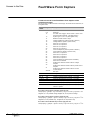
Access to the files
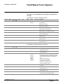
Fault Wave Form Capture
Descriptor of the Fault Wave Form Capture in the protection
manager
b Fault Wave Form capture configuration (Header)
register
address
nb of read/
reg. write
scale
unit
format
interval
9964
9963
1
R/W
-
-
INT
9965
9964
1
R
-
-
9966
9965
1
R
x1
9967
9966
1
R
9968
9967
1
9969
A/E
P/H
description
{0x0000,
0xFFFF}
H
file status :0xFFFF: file enabled
0: file disabled
default value: 0xFFFF
INT
22
H
type of file: Fault Wave Form Capture
default value: 22 (FWFC)
rec.
INT
22
H
size of file in number records
always equal to 22 records/file
x1
register
INT
64
H
size of records in number of registers
always equal to: 64 registers per record
R
-
-
INT
0
H
file filling mode : 1: disabled if log is full. 0:
circular. default value: 0
9968
R
1
segment
INT
1
H
number of 12 cycle segments
always equal to 1
9970
9969
R
1
cycle
INT
2
H
number of cycle before capture
always equal to 2
9971
9970
R
1
points
INT
16
H
number of points per cycle
always equal to 16
b Fault Wave Form capture characteristics (Status)
register
address
nb of read/
reg. write
scale
unit
format
interval
9980
9979
1
R
x1
rec.
INT
9981
9980
1
R
x1
register
9982
9981
1
R
x1
9983
9982
1
R
9984
9983
1
9985
9984
9986
9985
P/H
description
{0,22}
H
size of file in records
either equal to 0 or 22
INT
64
H
size of a record in registers
always equal to 64
-
INT
0,10,20,3
0,250,25
3,
254,255,
0Xff00,
0xFE00,
OxFD00,
OxFC00
H
0: file OK. 10: record size smaller than
expected. 20: record size larger than expected.
30: insufficient memory. 250: internal error. 253:
corrupted allocation table. 254: configuration
zero
255: invalid configuration
0xFF00: cannot allocate file
0xFE00: file not supported
0xFD00: invalid record number
0xFC00: invalid file number
x1
rec.
INT
{0,22}
H
Actual number of records in the file. Either equal
to 0 or 22
R
x1
rec.
INT
{0,1}
H
number of first record present
either equal to 0 or 1
1
R
x1
rec.
INT
{0,22}
H
number of last record present
either equal to 0 or 22
3
R
-
-
DATE
cfformat
H
date the last file was reset
Default value: 0x8000 0x8000 0x8000
COMBT32EN – 04/2011
A/E
35
Access to the files
Fault Wave Form Capture
Format of records in the Fault Wave Form Capture of the
protection manager
This file consists of a fixed number of records (22). All records are of similar size, i.e
64 registers wide.
Record
number
Registers
Description
1
1-4
5-11
12
Extended Date/time
Reserved
Id of fault WFC Trigger : Alarm number : 1000 to 1031
(See the section appendix : Trip/Alarm history)
System type :31, 40 or 41 (See register 3314)
Breaker nominal current in Amps
Voltage multiplier for phase A (format is SFIXPT)
Voltage Offset for phase A (format is INT)
Same as 15, for phase B
Same as 16, for phase B
Same as 15, for phase C
Same as 16, for phase C
Current multiplier for phase A (format is SFIXPT)
Current Offset for phase A (format is INT)
Same as 21, for phase B
Same as 22, for phase B
Same as 21, for phase C
Same as 22, for phase C
Current multiplier for Neutral (format is SFIXPT)
Same as 22, for Neutral
Scaling factor used for SFIXPT math on voltage
samples
Scaling factor used for SFIXPT math on phase current
samples
Scaling factor used for SFIXPT math on neutral
current samples
Not used
13
14
15
16
17
18
19
20
21
22
23
24
25
26
27
28
29
30
31
32 to 64
2 to 4
1-64
Voltage A Sample points (16 points – 12 cycles)
5 to 7
1-64
Voltage B Sample points (16 points – 12 cycles)
8 to 10
1-64
Voltage C Sample points (16 points – 12 cycles)
11 to 13
1-64
Current A Sample points (16 points – 12 cycles)
14 to 16
1-64
Current B Sample points (16 points – 12 cycles)
17 to 19
1-64
Current C Sample points (16 points – 12 cycles)
20 to 22
1-64
Current N Sample points (16 points – 12 cycles) Only
valid in 41 system
b In order to derive phase A Voltage, apply this rule:
st
Sample (Volt) = [(sample – reg.16 of 1st rec.) x reg 15 of 1st rec.] / reg.29 of 1 rec.
Register 18, 17 for phase B voltage; Register 20, 19 for phase C Voltage
b In order to derive phase A Current, apply this rule:
st
Sample (Amp) = [(sample – reg.22 of 1st rec.) x reg 21 of 1st rec.] / reg.30 of 1 rec.
Register 24, 23 for phase B Amp ; Register 26, 25 for phase C Amp
b In order to derive Neutral Amp Current, apply this rule:
st
Sample (Amp) = [(sample – reg.28 of 1st rec.) x reg 27 of 1st rec.] / reg.31 of 1 rec.
2
COMBT32EN – 04/2011
Modbus protocol
Generality
Introduction
Modbus is an application layer messaging protocol, positioned at level 7 of the OSI
model that provides client/server communication between devices connected on
different types of buses or networks.
The Internet community can access Modbus at a reserved system port 502 on the
TCP/IP stack.
Modbus is a request/reply protocol and offers services specified by function codes.
Modbus / Jbus protocol
In the Modbus protocol, register numbering begins with 1, whereas in the JBus
protocol, numbering of the equivalent registers begins with 0. However, a JBus
master can dialogue with a Modbus slave by addressing a register number - 1 to
access the correct register on the Modbus slave.
Example of a read request
In order to read the RMS current on phase 1 (contents of register 1016), you will
have to access the address number 1016 – 1 = 1015
1015 (decimal) = 0x03F7 (hexa)
Request
Response
Function
03
Function
03
Starting Address Hi
03
Byte count
02
Starting Address Lo
F7
Register value
Hi
02
N° of registers
Hi
00
Register value
Lo
2B
N° of registers
Lo
01
The contents of register 1016 (RMS current on phase 1) are shown as the two byte
values of 02 2B (hexa), or 555 decimal.
Therefore, RMS current on phase 1 is 555 Amps.
Modbus exception responses
When a client device (master) sends a request to a server device (slave) it expects
a normal response. One of four possible events can occur from the master’s query:
b If the server device receives the request without a communication error,
and can handle the query normally, it returns a normal response.
b If the server device does not receive the request due to a communication
error, no response is returned. The client program will eventually process a
timeout condition for the request.
b If the server device receives the request, but detects a communication
error (parity, LRC, CRC…), no response is returned. The client program will
eventually process a timeout condition for the request.
b If the server device receives the request without a communication error,
but cannot handle it (for example, if the request is to read a non existing
register), the server will return an exception response informing the client of
the nature of the error.
The exception response message has two fields that differentiate it from a normal
response:
Function code: Function code of the original request + 0x80 (hexa)
Exception code: See list below
ILLEGAL FUNCTION
ILLEGAL DATA ADDRESS
ILLEGAL DATA VALUE
SLAVE DEVICE FAILURE
ACKNOWLEDGE (in conjunction with programming commands)
SLAVE DEVICE BUSY (in conjunction with programming commands)
MEMORY PARITY ERROR (with function code 0x14)
COMBT32EN – 04/2011
37
Modbus protocol
Modbus functions
Read functions
Function
code
3
Subfunction
Description
Read n output or internal registers (1) (2)
4
Read n input registers (1) (2)
23
Simultaneously read/write n and p registers (1) (2)
43
Read Device Identification (3)
Read device identification example
The Read Device Identification function is used to access in a standardized manner the information
required to clearly identify a device. The description is made up of a set of objects (ASCII character
strings)
A complete description of the Read Device Identification function is available at www.modbus.org.
The coding for the identification of the Breaker Communication Module is the following:
Name
Type Description
Vendor name
String ‘Schneider Electric’ (18 characters)
Product code
String ‘33106’
Firmware version
String ‘VX.Y.Z’
Vendor URL
String ‘www.schneider-electric.com’
Product name
String ‘BCM ULP’
Protection type
String ‘XY’
Metering type
String ‘z’
Write functions
Function
code
6
Subfunction
Description
Write one register
(1) (2)
16
Write n registers
22
Write one register with mask
23
Simultaneously read/write n and p registers
(1) (2)
(1)
Registers 4XXXX and 3XXXX are linked to the same data in registers XXXX in the data tables
The n (or p) words constitute a block specified by the basic block address and the size of the block.
(3)
Read Device Identification is available only with a Breaker Communication Module firmware version
greater or equal to V3.0 (register 577 must be greater or equal to 03000).
(2)
Diagnosis functions
These functions act exclusively on the circuit-breaker manager (@ xx) and the chassis manager
(@ xx +50).
Function
SubDescription
code
function
8
Management of the diagnostics counters
COMBT32EN – 04/2011
8
10
Clear the diagnostics counters
8
11
Read the bus-messages counter managed by the slave
8
12
Read the bus-errors counter managed by the slave
8
13
Read the bus exception answer counter managed by the slave
8
14
Read the counter for messages sent to the slave
8
15
Read the counter for messages sent to the slave and to which the
slave did not answer
8
16
Read the counter for messages sent to the slave and to which the
slave replied with an exception code 07 "Negative Acknowledge"
8
17
Read the counter for messages sent to the slave and to which the
slave replied with an exception code 06 "Slave Device Busy"
8
18
Read the counter for messages sent to the slave that it could not
process due to a transmission error
11
Read the Modbus event counter
17
Read the identifier of the Modbus slave
38
Modbus protocol
Modbus functions
Read File Record: function 20 (0x14)
This function acts exclusively on the protection manager (@ xx +100) and the metering manager
(@ xx +200).
This function code is used to perform a file record read. All Request Data Lengths are provided in
terms of number of bytes and all Record Lengths are provided in terms of registers.
The quantity of registers to be read combined with all other fields in the expected response must
not exceed the allowable length of Modbus messages: 256 bytes.
Request
Response
Function code
1 Byte
0x14
Function
1 Byte
0x14
Byte count
1 Byte
0x07
Data Length
1 Byte
2 + Nx2
Reference Type
1 Byte
0x06
File Resp.Length 1 Byte
1 + Nx2
File number
2 Bytes 0x0000 to 0xFFFF Reference type
1 Byte
0x06
Record number
2 Bytes 0x0000 to 0x270F Record Data
Nx2 Bytes Data
Record length
2 Bytes N
Example of a request to read the most recent record in the event log of
the protection manager
The event log of the protection manager is the file N° 20 (0x0014). This file is made up of 100
records; each record is made up of 9 registers. So, the record length is 9 (0x0009). The sequence
number of last record in the file (the most recent) is the content of register 9921.
Let’s take 0x1234 for the content of register 9921.
Request
Response
Function code
1 Byte
0x14
Function
1 Byte
0x14
Byte count
1 Byte
0x07
Data Length
1 Byte
0x14
Reference Type
1 Byte
0x06
File Resp.Length 1 Byte
0x13
File number
2 Bytes 0x0014
Reference type
1 Byte
0x06
Record number
2 Bytes 0x1234
Record Data
9x2 Bytes Data
Record length
2 Bytes 0x0009
COMBT32EN – 04/2011
39
Modbus protocol
Modbus functions
Read n non-contiguous words (function 100, sub-function 4)
The n non-contiguous registers must be specified one after the other by their register in the data
table. The Maximum for n is 100 (When using Micrologic A, it is recommended to have n lower or
equal to 21).
To optimise access to Micrologic and its COM options, it may be very useful to read n noncontiguous registers in a data table.
Use of function 100, sub-function 4 avoids:
b reading a large block of contiguous data when only a few elements of data are required
b multiplying read functions for n registers (functions 3 and 4) or for one register (function
1) simply to read a few elements of non-contiguous data.
The table below provides an example of reading the data in registers 101 and 103 of the slave with
the Modbus address 47.
Request
Answer
Name of field
Example
Name of field
Example
Slave address
47
Slave address (identical)
47
100
Function
6
Number of bytes requested 6
and returned + 2
4
Sub-function code
Function
(1)
Number of registers read +2
Sub-function code
(1)
Transmission number
(2)
(1)
100
(1)
4
(2)
0xXX
Transmission number
Address of first register to
read (most significant byte)
0
First register read (most
significant byte)
0x12
0xXX
Address of first register to
read (least significant byte)
101
First word register (least
significant byte)
0x0A
Address of second register to 0
read (most significant byte)
Second register read (most 0xFA
significant byte)
Address of second register to 103
read (least significant byte)
Second register read (least 0x0C
significant byte)
CRC high
XX
CRC high
XX
CRC low
XX
CRC low
XX
Note.
(1)
These values are constant.
(2)
The transmission number is provided by the master prior to each request for a non-contiguous read. The slave
device must return the same number.
COMBT32EN – 04/2011
40
Appendix
Format
UINT
UINT corresponds to a 16-bit unsigned integer with an interval of values from 0x0000…0xFFFF
(0…65535).
INT
INT corresponds to a 16-bit signed integer with an interval of values from 0x8000…0x7FFF (32768…+32767).
UDINT
UDINT corresponds to a 32-bit unsigned integer with an interval of values from
0x00000000…0xFFFFFFFF (0…4 294 967 295).
DINT
DINT corresponds to a 32-bit signed integer with an interval of values from
0x00000000…0xFFFFFFFF (-2 147 483 648…+2 147 483 647).
Mod10000
Mod10000 corresponds to n registers in the INT format.
Each register contains an integer from 0 to 9999. A value V representing n registers is calculated
as indicated below.
(m-1)
),
V = sum(R[n] + R[n+ 1] x 10000 + ..+ R[n+m] x 10000
where Rn is the number of register n.
Example: Register 2000 = 123 ; Register 2001 = 4567; Register 2002 = 89 ; Register 2003=0
Energy = 123 + 4567x10 000 + 89x (10 000)² + 0 = 89 4567 0123 kWh
SFIXPT
SFIXPT corresponds to a signed INT integer with a fixed point. The position of the point is
indicated by the scale factor. The interval of values is:
-32767…+32767 with a scale factor "x1".
Other example:
-32.767…+32.767 with a scale factor "x1000".
DATE
Date corresponds to a normal date made up of three UINT, as follows:
b first UINT:
month expressed using the eight most-significant bits (January = 0x41)
(1)
day expressed using the eight least-significant bits
Example: 0x0519 = May 25
b second UINT:
year expressed using the eight most-significant bits (modulo 100)
(00 to 49 Æ years 2000 to 2049, from 50 to 99 Æ years 1950 to 1999)
hours expressed using the eight least-significant bits
Example: 0x6e12 = 2010 18h
b third UINT:
minutes expressed using the eight most-significant bits
seconds expressed using the eight least-significant bits.
Example: 0x1a39 = 26mn 57s
Note.
(1)
If the most-significant bit is set, the date and time may be incorrect. There are two possibilities:
- no synchronisation with the supervisor
- loss of power.
If power has been lost, the self-test bitmap "D/T loss" is enabled until the date and time are enabled (via the
control unit or the communication manager).
COMBT32EN – 04/2011
41
Appendix
Trip/Alarm history
XDATE
XDATE corresponds to an extended date made up of four UINT, as follows:
b first UINT:
(1)
month expressed using the eight most-significant bits (January = 0x41)
day expressed using the eight least-significant bits
b second UINT:
year expressed using the eight most-significant bits (modulo 100)
(00 to 49 Æ years 2000 to 2049, from 50 to 99 Æ years 1950 to 1999)
hours expressed using the eight least-significant bits
b third UINT:
minutes expressed using the eight most-significant bits
seconds expressed using the eight least-significant bits.
b fourth UINT: milliseconds.
ASCII
ASCII corresponds to a series of n UINT registers forming a sting of ASCII characters. The first
character is contained in the eight most-significant bits of the register. The start of the string is in
the first register.
Note.
(1)
If the most-significant bit is set, the date and time may be incorrect. There are two possibilities:
- no synchronisation with the supervisor
- loss of power.
If power has been lost, the self-test bitmap "D/T loss" is enabled until the date and time are enabled (via the
control unit or the communication manager).
TRIP RECORD
TRIP RECORD format matches the trip history displayed on the graphic screen of the Micrologic
(E, P, and H only).
TRIP RECORD format presents the characteristics of a fault trip. It corresponds to a series of ten
fields (9100, 9120, 9140… 9280) with a total of 20 registers.
Register 9098 returns the number of faults recorded in the trip history (FIFO)
Register 9099 return the value of the pointer for the last fault recorded in the trip history.
Each field (containing 20 registers) is presented below:
Field
___.XtedDT
Nb of reg.
4
Format
XDATE
Interval
Cfformat
N/A
0x8000
Description
Trip date
___.ActCause
AlarmNum
1
INT
0..1031
0x8000
Number of alarm causing activation
___.PuValue
2
MOD
10000
See text
0x8000
Value of protection setting that caused trip
___.PuDelay
1
INT
See text
0x8000
Value of time delay that caused trip
___.FaultI[0]
1
INT
0..16000
0x8000
Trip current phase 1, expressed with respect to the rated current
(1) (2)
___.FaultI[1]
1
INT
0..16000
0x8000
Trip current phase 2, expressed with respect to the rated current
(1) (2)
___.FaultI[2]
1
INT
0..16000
0x8000
Trip current phase 3, expressed with respect to the rated current
(1) (2)
___.FaultI[3]
1
INT
0..16000
0x8000
Trip current on neutral, expressed with respect to the rated current
___.WorstContac
tWear
1
INT
0..32767
0x8000
New value of contact-wear indicator following a trip. The control unit
records one indicator per contact. Here, only the value for the most
worn contact is given. (See registers 9094 to 9097)
___.AddInfo
2
See text
See text
0x8000
Reserved
___.Reserved
5
-
-
0x8000
Reserved
(1)
(2)
(2)
(2)
(1) (2)
Expressed as x 0.1 of In (rated current).
Not available with Micrologic E.
COMBT32EN – 04/2011
42
(2)
Appendix
Trip/Alarm history
ALARM RECORD
ALARM RECORD format matches the alarm history displayed on the graphic screen of the
Micrologic (P, H only).
ALARM RECORD format presents the characteristics of a fault alarm. It corresponds to a series of
ten fields (9302, 9317, 9332… 9437) with a total of 15 registers.
Register 9300 returns the number of alarms recorded in the alarm history (FIFO)
Register 9301 return the value of the pointer for the last alarm recorded in the alarm history.
Each field (containing 15 registers) is presented below:
Field
___.XtedDT
Nb of reg.
4
Format
XDATE
Interval
cfformat
N/A
0x8000
Description
Alarm date
___.ActCause
AlarmNum
1
INT
0..1031
0x8000
Number of alarm causing activation
___.PuValue
2
MOD
10000
See text
0x8000
Value of protection setting that caused alarm activation
___.PuDelay
1
INT
See text
0x8000
Value of time delay that caused alarm activation
___.FaultI[0]
1
INT
0..16000
0x8000
Alarm current phase 1, expressed with respect to the rated current
___.FaultI[1]
1
INT
0..16000
0x8000
Alarm current phase 2, expressed with respect to the rated current
(1)
___.FaultI[2]
1
INT
0..16000
0x8000
Alarm current phase 3, expressed with respect to the rated current
(1)
___.FaultI[3]
1
INT
0..16000
0x8000
Alarm current on neutral, expressed with respect to the rated current
___.AddInfo
2
See text
See text
0x8000
Additional information, depending on type of alarm
___.Reserved
1
-
-
0x8000
Reserved
(1)
COMBT32EN – 04/2011
(1)
Expressed as x 0.1 of In (rated current)
43
(1)
Appendix
Trip/Alarm history
Alarm numbers
b Basic protections
Description
Trip due to Long-time protection
Ir
Number
1000
Trip due to Short-time protection
Isd
1001
Trip due to Instantaneous protection
Ii
1002
Trip due to Ground-fault protection
Ig
1003
Trip due to Earth-leakage protection
IDelta n
1004
Trip due to Integrated instantaneous protection
Reserved
I >>
1005
1006 to 1007
Trip due to advanced protection
1008
Trip due to extended advanced protection
1009
Reserved
1010
Reserved
1011 to 1012
Long time protection alarm
1013
Ground-fault protection alarm
1014
Earth-leakage protection alarm
1015
b Advanced protections
Description
Current unbalance
Number
1016
Ia Max demand
1017
Ib Max demand
1018
Ic Max demand
1019
IN Max demand
1020
Under voltage
1021
Over voltage
1022
Voltage unbalance
1023
Reverse power
1025
Under frequency
1026
Over frequency
1027
Phase rotation
1028
Current load shedding
1029
Power load shedding
1030
Reserved
1031
b Digital alarms
COMBT32EN – 04/2011
Description
System energised / reset
Number
1100
Reserved
1101 to 1105
Loss of date and time
1106
Reserved
1107 to 1114
Battery low
1115
44
Appendix
Table of registers
Structure of the table
Each Modbus logical table is made up of the fields listed below.
b register: number of the Modbus register.
b nbr of registers: number of registers that must be read or written for a given complete
piece of information. This datum indicates the type of register (8-bit, 16-bit or 32-bit word).
b read/write:
"R": register that may be accessed by the Modbus read functions 3, 4, 23, 20, 100 (see page 40).
Modbus function 20 is supported by the Metering and Protection managers only.
"W": register that may be accessed by the Modbus write functions 6, 16, 22, 23 (see page 40)
"R/W": register that may be read and write accessed.
b scale (x n): value contained in the register multiplied by n. The requested information is
obtained by dividing the register contents by n. The result in expressed in the indicated
unit.
Example:
Register 1054 contains the frequency. The unit is Hz and the scale factor is 10.
If the register returns 504, this means that the frequency is 504/10 = 50.4 Hz.
b unit: unit of measurement for the value contained in the register.
b format: format in which the information is coded.
b interval: interval of the possible values that each register in the group {Register, Register
+1,..., Register + Nb} can have.
b A, E, P, H: type of control unit using the register:
"A": Micrologic A control unit
"E": Micrologic E control unit
"P": Micrologic P control unit
“H”: Micrologic H control unit
b description: additional information describing the register, providing coding data and any
necessary information on how to modify the register, particularly when the command
interface is required to carry out the modification.
COMBT32EN – 04/2011
45
Appendix
Table of registers
Circuit-breaker manager @ xx
Configuration of the circuit-breaker manager
register
address
nb of read/
reg. write
scale
unit
format
interval
A/E
P/H
description
515
514
1
R
-
-
INT
15139
A/E
P/H Square D Product Identification
15139 = Breaker Communication Module
531
530
1
R/W
-
-
INT
1..47
A/E
P/H MODBUS address of the COM option (@XX)
Default value: 47
532
531
1
R/W
-
-
INT
0..1
A/E
P/H Parity:
0: no parity
1: even parity
Default value: 1
533
532
1
R/W
-
-
INT
1200..
38400
A/E
P/H Baud rate:
1200: 1200 baud
2400: 2400 baud
4800: 4800 baud
9600: 9600 baud
19200: 19200 baud
38400: 38400 baud
Default value: 19200
Identification of the circuit-breaker manager
register
address
nb of read/
reg. write
scale
unit
format
interval
A/E
P/H
534
533
2
R/W
-
-
ASCII
0x00..
0x7F7F
A/E
P/H short identifier of circuit-breaker COM option,
coded over 4 ASCII characters
Default value: 0x00
536
535
8
R/W
-
-
ASCII
0x00..
0x7F7F
A/E
P/H long identifier of circuit-breaker COM option,
coded over 16 ASCII characters
Default value: 0x00
COMBT32EN – 04/2011
description
46
Appendix
Table of registers
Circuit-breaker manager @ xx
Diagnostics counters and Control word
register
address
nb of read/
reg. write
scale
unit
format
interval
A/E
P/H
544
543
1
R
-
-
INT
0..32767
A/E
P/H Modbus diagnostics counter – messages sent to
(2)
the slave (identical to function 8-14)
545
544
1
R
-
-
INT
0..32767
A/E
P/H Modbus diagnostics counter – messages sent to
(2)
other slaves
546
545
1
R
-
-
INT
0..32767
A/E
P/H Modbus diagnostics counter – bus messages
(2)
managed by the slave (identical to function 8-11)
547
546
1
R
-
-
INT
0..32767
A/E
P/H Modbus diagnostics counter –bus errors managed
(2)
by the slave (identical to function 8-12)
548
547
1
R
-
-
INT
0..32767
A/E
P/H Modbus diagnostics counter – messages sent to
the slave comprising a non-supported Modbus
(2)
function
549
548
1
R
-
-
INT
0..32767
A/E
P/H Modbus event counter (identical to function 11)
550
549
1
R
-
-
INT
0..32767
A/E
P/H Modbus diagnostics counter –bus exception replies
(2)
managed by the slave (identical to function 8-13)
551
550
1
R
-
-
INT
0..32767
A/E
P/H Modbus diagnostics counter – broadcast messages
(2)
received by the slave (identical to function 8-15)
553
552
1
R
-
-
INT
0..65535
A/E
P/H Control word of the circuit-breaker COM option.
This Control word cannot be set by the user. It is
randomly changed each time the system is
energised. It is necessary to read the Control word
before sending certain commands to the circuitbreaker COM option.
554
553
1
R
-
-
INT
0..65535
A/E
P/H Counter for number of times the circuit-breaker
(1)
COM option is energised
555
554
1
R
-
-
INT
0..65535
A/E
P/H Counter for the number of circuit-breaker COM
(1)
option resets, whether following power loss or not.
577
576
1
R
1
-
INT
-
A/E
P/H Breaker Communication Module firmware version
580
579
1
R/W
1
-
INT
0..65535
A/E
P/H OF counter threshold (default value = 5000)
581
580
1
R/W
1
-
INT
0..65535
A/E
P/H Close command counter threshold (default value =
5000)
(1)
(2)
description
(2)
The counter automatically cycles from 65535 to 0.
The counter automatically cycles from 32767 to 0.
Metering/protection-manager event notification
register
address
nb of read/
reg. write
scale
unit
format
interval
A/E
P/H
description
603
602
1
R
-
-
INT
1..8000
-
H
number of first (oldest) record in the meteringmanager event log (file N° 10)
604
603
1
R
-
-
INT
1..8000
-
H
number of last (most recent) record in the
metering-manager event log (file N° 10)
623
622
1
R
-
-
INT
1..8000
-
P/H number of first (oldest) record in the protectionmanager event log (file N° 20)
624
623
1
R
-
-
INT
1..8000
-
P/H number of last (most recent) record in the
protection-manager event log (file N° 20)
COMBT32EN – 04/2011
47
Appendix
Table of registers
Circuit-breaker manager @ xx
Cause of tripping
register
address
nb of
reg.
read/
write
scale
unit
format
interval
650
649
1
R
-
-
INT
0..65535
A/E
A/E
A/E
A/E
A/E
A
P/H
P/H
P/H
P/H
Bitmap indicating cause of tripping for basic
protection functions:
0x01: long-time protection. Ir
0x02: short-time protection Isd
0x04: instantaneous protection Ii
0x08: ground-fault protection Ig
0x10: earth-leakage protection (vigi)
0x20: Integrated Instantaneous protection
0x40: Integrated Instantaneous protection
0x40: Internal failure (temperature
0x80: Internal failure (overvoltage)
0x0100: Other protection (see register 651)
P/H
P/H
P/H
P/H
P/H
P/H
P/H
P/H
P/H
P/H
P/H
P/H
P/H
P/H
P/H
Bitmap indicating cause of tripping for advanced
protection functions:
0x01: current unbalance
0x02: Over current phase 1
0x04 Over current phase 2
0x08: Over current phase 3
0x10: Over current on Neutral
0x20: Under voltage
0x40: Over voltage
0x80: voltage unbalance
0x0100: Over power
0x0200: reverse power
0x0400: Under frequency
0x0800: Over frequency
0x1000: phase rotation
0x2000: load shedding based on current
0x4000: load shedding based on power
P/H
P/H
P/H
P/H
P/H
P/H
A/E
A/E
651
650
1
R
-
-
INT
description
0..65535
Note: The bit indicating the cause of tripping is set as soon as a trip
occurs. The bit is reset as soon as the circuit-breaker is closed again.
COMBT32EN – 04/2011
48
Appendix
Table of registers
Circuit-breaker manager @ xx
Circuit-breaker status, Auto/Manu
register
address
nb of read/
reg. write
scale
unit
format
interval
A/E
P/H
661
660
1
R
-
-
Bitmap16
-
A/E
P/H Circuit-breaker status:
See next page
662
661
1
R
-
-
INT
0..65535
A/E
P/H counter for total number of operations (OF): the
counter increments when bit 0 in register 661
(1)
switches from 0 to 1.
663
662
1
R
-
-
INT
0..65535
A/E
P/H counter for operations (OF) since last reset: the
counter increments when bit 0 in register 661
(1)
switches from 0 to 1.
664
663
1
R
-
-
INT
0..65535
A/E
P/H counter for operations (SD): the counter
increments when bit 1 in register 661 switches
(1)
from 0 to 1.
665
664
1
R
-
-
INT
0..65535
A/E
P/H counter for operations (SDE): the counter
increments when bit 2 in register 661 switches
(1)
from 0 to 1.
669
668
1
R
-
-
Bitmap16
0..65535
A/E
P/H authorisation word for actuation by MX and XF
auxiliaries:
when bit 1 and 3 are set, MX is authorised to
actuate the circuit breaker
when bit 2 and 3 are set, XF is authorised to
actuate the circuit breaker
670
669
1
R
-
-
INT
0..1
A/E
P/H Auto/Manu (Remote/Local mode) :
0, "Manu" (Local mode) : remote opening and
closing of the circuit breaker are disabled
1, "Auto" (Remote mode) : remote opening and
closing of the circuit breaker are enabled
Auto/Manu mode can be modified via the HMI of
Micrologic P/H (only locally).
Default value = 1
(1)
description
The counter automatically cycles from 65535 to 0.
OF ON / OFF.
SD Trip indication.
SDE Fault-trip indication.
COMBT32EN – 04/2011
49
Appendix
Table of registers
Circuit-breaker manager @ xx
List of possible values for register 661 (circuit-breaker status)
in the circuit-breaker manager
BrStatus bitmap detail :
Bit 0 (0x01) : OF ; Indication contacts
For Compact and Masterpact :
0= Breaker is opened , 1 = Breaker is closed
Bit 1 (0x02) : SD ; Trip indication contact
For Compact :
0 = no trip
1 = Breaker has tripped due to electrical fault
or Shunt trip or Push to trip
For Masterpact : always 0
Bit 2 (0x04) : SDE ; Fault trip indication contact
For Compact and Masterpact :
0 = no trip
1 = Breaker has tripped due to electrical fault
(including Ground Fault test and Earth leakage test).
Bit 3 (0x08) : CH ; Charged (used only with motor mechanism)
For Compact : always 0
For Masterpact :
0 = Spring discharged, 1 = Spring loaded
Bit 4 (0x10) : Reserved (internal use only)
Bit 5 (0x20) : Reserved (internal use only)
Bit 6 (0x40) : Compact / Masterpact differenciation
0 = Compact NS , 1 = Masterpact
Bit 7-15 : Reserved
Note :
A bitmap mask should be used to test the Breaker status.
If a value test is used, the following values should be used for Mastepact :
0x44 Tripped discharged not RTC
0x4C Tripped charged not RTC
0x50 OFF discharged not RTC
0x51 ON discharged not RTC
0x59 ON charged not RTC
0x78 OFF charged RTC
COMBT32EN – 04/2011
50
Appendix
Table of registers
Circuit-breaker manager @ xx
Time stamping
register
address
nb of read/
reg. write
scale
unit
format
interval
A/E
P/H
description
671
670
3
R
-
-
DATE
-
A/E
P/H date of last actuation
of MX auxiliary
674
673
1
R
-
-
INT
0..65535
A/E
P/H MX actuation counter
675
674
3
R
-
-
DATE
-
A/E
P/H date of last actuation
of XF auxiliary
678
677
1
R
-
-
INT
0..65535
A/E
P/H XF actuation counter
679
678
4
R
-
-
XDATE
-
A/E
P/H current date of circuit-breaker COM option
P/H date of last circuit-breaker
opening
(1)
(1)
684
683
3
R
-
-
DATE
-
A/E
687
686
3
R
-
-
DATE
-
A/E
P/H date of last circuit-breaker
closing
690
689
3
R
-
-
DATE
-
A/E
P/H date of last trip without
an electrical fault
693
692
3
R
-
-
DATE
-
A/E
P/H date of last trip with
an electrical fault
696
695
3
R
-
-
DATE
-
A/E
P/H date of last PAF (Ready To Close) closing
P/H date of last DLO (half moon) closing
699
698
3
R
-
-
DATE
-
A/E
702
701
3
R
-
-
DATE
-
A/E
P/H date of last AD (charged) closing
P/H date of last address change
(register 531)
705
704
3
R
-
-
DATE
-
A/E
708
707
3
R
-
-
DATE
-
A/E
P/H date of last reset of circuit-breaker COM option event
log
711
710
4
R
-
-
XDATE
-
A/E
P/H date when time for circuit-breaker COM option was
last set
715
714
1
R
-
-
INT
0..65535
A/E
P/H counter for time setting for circuit-breaker COM option
800
799
1
R/W
0…1
A/E
P/H Communication profile activation
0 = Not activated
1 = activated
(2)
Default value = 0 (firmware version smaller to V3.0)
Default value = 1 (firmware version greater or equal
to V3.0
802
801
1
R
A/E
P/H Open command status
P/H Close command status
P/H 4 Wire / 2 Wire+ULP communication parameter
0 = 4 wire
1 = 2 Wire+ULP
Default value = 0
(1)
803
802
1
R
A/E
806
805
1
R/W
A/E
Event log of the circuit-breaker manager
Registers 718 Æ 740 file N° 30 (see the section: Access to the files)
The counter automatically cycles from 65535 to 0.
Communication profile is available only with a Breaker Communication Module firmware version
greater or equal to V2.0 (register 577 must be greater or equal to 02000)
COMBT32EN – 04/2011
51
Appendix
Table of registers
Chassis manager @ xx + 50
Configuration of the chassis manager
register
address
nb of read/
reg. write
scale
unit
format
interval
A/E
P/H
description
515
514
1
R
-
-
INT
15140
A/E
P/H Square D Product Identification
15140 = Chassis Communication Module
531
530
1
R/W
-
-
INT
51..97
A/E
P/H MODBUS address of the COM option (@ xx + 50)
Default value: 50+47=97
532
531
1
R/W
-
-
INT
0..1
A/E
P/H Parity:
0: no parity
1: even parity
Default value: 1
533
532
1
R/W
-
-
INT
1200..
38400
A/E
P/H Baud rate:
1200: 1200 baud
2400: 2400 baud
4800: 4800 baud
9600: 9600 baud
19200: 19200 baud
38400: 38400 baud
Default value: 19200
Identification of the chassis manager
register
address
nb of read/
reg. write
scale
unit
format
interval
A/E
P/H
description
534
533
2
R/W
-
-
ASCII
0x00..
0x7F
A/E
P/H
short identifier of the chassis COM option coded
over 4 ASCII characters
Default value: 0x00
536
535
8
R/W
-
-
ASCII
0x00..
0x7F
A/E
P/H
long identifier of the chassis COM option coded
over 16 ASCII characters
Default value: 0x00
COMBT32EN – 04/2011
52
Appendix
Table of registers
Chassis manager @ xx + 50
Diagnostics counters and Control word
register
address
nb of read/
reg. write
544
543
1
R
545
544
1
R
546
545
1
547
546
548
scale
unit
format
interval
A/E
P/H
description
-
INT
0..32767
A/E
P/H Modbus diagnostics counter – messages sent to
(2)
the slave (identical to function 8-14)
-
-
INT
0..32767
A/E
P/H Modbus diagnostics counter – messages sent to
(2)
other slaves
R
-
-
INT
0..32767
A/E
P/H Modbus diagnostics counter – bus messages
(2)
managed by the slave (identical to function 8-11)
1
R
-
-
INT
0..32767
A/E
P/H Modbus diagnostics counter –bus errors managed
(2)
by the slave (identical to function 8-12)
547
1
R
-
-
INT
0..32767
A/E
P/H Modbus diagnostics counter – messages sent to
the slave comprising a non-supported Modbus
(2)
function
549
548
1
R
-
-
INT
0..32767
A/E
P/H Modbus event counter (identical to function 11)
550
549
1
R
-
-
INT
0..32767
A/E
P/H Modbus diagnostics counter –bus exception
replies managed by the slave (identical to function
(2)
8-13)
551
550
1
R
-
-
INT
0..32767
A/E
P/H Modbus diagnostics counter – broadcast
messages received by the slave (identical to
(2)
function 8-17)
553
552
1
R
-
-
INT
0..65535
A/E
P/H Control word of the chassis manager. This Control
word cannot be set by the user. It is randomly
changed each time the system is energised. It is
necessary to read the Control word before sending
certain commands to the chassis manager.
554
553
1
R
-
-
INT
0..65535
A/E
P/H Counter for number of times the circuit-breaker
(1)
COM option is energised
555
554
1
R
-
-
INT
0..65535
A/E
P/H Counter for the number of circuit-breaker COM
option resets, whether following power loss or not.
(1)
577
576
1
R
1
-
INT
A/E
(1)
(2)
COMBT32EN – 04/2011
P/H Chassis Communication firmware version
The counter automatically cycles from 65535 to 0.
The counter automatically cycles from 32767 to 0.
53
(2)
Appendix
Table of registers
Chassis manager @ xx + 50
Chassis status
register
address
nb of read/
reg. write
scale
unit
format
interval
A/E
P/H
661
660
1
R
-
-
Bitmap 16
-
A/E
P/H device status:
If bit 9 (0x0200) is set to 1, the device is
connected. CE
If bit 8 (0x0100) is set to 1, the device is
disconnected. CD
If bit 10 (0x400) is set to 1, the device is in the
test position. CT
662
661
1
R
-
-
INT
0..65535
A/E
P/H counter for change to the "connected" position:
the counter increments when bit 8 in register 661
(1)
switches from 0 to 1.
663
662
1
R
-
-
INT
0..65535
A/E
P/H counter for change to the "disconnected" position:
the counter increments when bit 9 in register 661
.(1)
switches from 0 to 1
664
663
1
R
-
-
INT
0..65535
A/E
P/H counter for change to the "test" position: the
counter increments when bit 10 in register 661
(1)
switches from 0 to 1.
(1)
description
The counter automatically cycles from 65535 to 0.
Time-stamping
register
address
nb of read/
reg. write
scale
unit
format
interval
A/E
P/H
679
678
4
-
-
XDATE
-
A/E
P/H current date of chassis COM option
P/H date of the last change to the
"connected" position
R
description
684
683
3
R
-
-
DATE
-
A/E
687
686
3
R
-
-
DATE
-
A/E
P/H date of the last change to the "disconnected"
position
690
989
3
R
-
-
DATE
-
A/E
P/H date of the last change to the
"test" position
705
704
3
R
-
-
DATE
-
A/E
P/H date of the last change in address
(register 531)
711
710
4
R
-
-
XDATE
-
A/E
P/H date when time for chassis COM
option was last set
715
714
1
R
-
-
INT
0..65535
A/E
P/H counter for time setting for chassis
COM option
COMBT32EN – 04/2011
54
Appendix
Table of registers
Metering manager @ xx + 200
Voltages
register
address
nb of read/
reg. write
scale
unit
format
interval
A/E
P/H
description
1000
999
1
R
x1
V
INT
0..1200
E
P/H
RMS phase-to-phase voltage V12
1001
1000
1
R
x1
V
INT
0..1200
E
P/H
RMS phase-to-phase voltage V23
1002
1001
1
R
x1
V
INT
0..1200
E
P/H
RMS phase-to-phase voltage V31
1003
1002
1
R
x1
V
INT
0..1200
E
(1)
1004
1003
1
R
x1
V
INT
0..1200
E
(1)
P/H
1005
1004
1
R
x1
V
INT
0..1200
E
(1)
P/H
RMS phase-to-neutral voltage V3N.
1006
1005
1
R
x1
V
INT
0..1200
E
P/H
arithmetic mean of the phase-to-phase voltages
1/3 x (V12+V23+V31).
1007
1006
1
R
x1
V
INT
0..1200
E
P/H
arithmetic mean of the phase-to-neutral
(1)
voltages 1/3 x (V1N+V2N+V3N).
1008
1007
1
R
x10
%
INT
-1000..
+1000
E
P/H
V12 phase-to-phase voltage unbalance with
respect to the arithmetic mean of the phase-tophase voltages
1009
1008
1
R
x10
%
INT
-1000..
+1000
E
P/H
V23 phase-to-phase voltage unbalance with
respect to the arithmetic mean of the phase-tophase voltages
1010
1009
1
R
x10
%
INT
-1000..
+1000
E
P/H
V31 phase-to-phase voltage unbalance with
respect to the arithmetic mean of the phase-tophase voltages
1011
1010
1
R
x10
%
INT
-1000..
+1000
E
P/H
V1N phase-to-neutral voltage unbalance with
respect to the arithmetic mean of the phase-to(1)
neutral voltages
1012
1011
1
R
x10
%
INT
-1000..
+1000
E
P/H
V2N phase-to-neutral voltage unbalance with
respect to the arithmetic mean of the phase-to(1)
neutral voltages
1013
1012
1
R
x10
%
INT
-1000..
+1000
E
P/H
V3N phase-to-neutral voltage unbalance with
respect to the arithmetic mean of the phase-to(1)
neutral voltages
1014
1013
1
R
x10
%
INT
-1000..
+1000
E
P/H
maximum phase-to-phase voltage unbalance
value in registers 1008, 1009 and 1010
1015
1014
1
R
x10
%
INT
-1000..
+1000
E
P/H
maximum phase-to-neutral voltage unbalance
(1)
value in registers 1011, 1012 and 1013
(1)
COMBT32EN – 04/2011
(1)
(1)
RMS phase-to-neutral voltage V1N.
(1)
RMS phase-to-neutral voltage V2N
(1)
P/H
.
Value not accessible when the configuration register 3314 selects type 31..
55
Appendix
Table of registers
Metering manager @ xx + 200
Currents
register
address
nb of read/
reg. write
scale
unit
format
interval
A/E
P/H
1016
1015
1
x1
A
INT
0..32767
A/E
P/H RMS current on phase 1.
P/H RMS current on phase 2
R
description
1017
1016
1
R
x1
A
INT
0..32767
A/E
1018
1017
1
R
x1
A
INT
0..32767
A/E
P/H RMS current on phase 3
P/H RMS current on the neutral
1019
1018
1
R
x1
A
INT
0..32767
A/E
1020
1019
1
R
x1
A
INT
0..32767
A/E
P/H maximum RMS current in registers 1016, 1017,
1018 and 1019
1021
1020
1
R
x1
A
INT
0..32767
A/E
P/H ground-fault current
If this current exceeds 32767 A, the register blocks
(3)
at 32767
1022
1021
1
R
x1
mA
INT
0..32767
A/E
P/H earth-leakage current
If this current exceeds 32767 A, the register blocks
at 32767 (4)
1023
1022
1
R
X1
A
INT
0..32767
H
Apparent current phase 1 (peak/ √2
1024
1023
1
R
X1
A
INT
0..32767
H
Apparent current phase 2 (peak/ √2
1025
1024
1
R
X1
A
INT
0..32767
H
Apparent current phase 3 (peak/ √2
1026
1025
1
R
X1
A
INT
0..32767
H
Apparent current Neutral (peak/ √2
1027
1026
1
R
x1
A
INT
0..32767
E
P/H arithmetic mean of phase currents 1, 2 and 3: 1/3 x
(I1+I2+I3)
1028
1027
1
R
x10
%
INT
-1000..
+1000
E
P/H
(2)
I1 current unbalance with respect to the arithmetic
mean of the phase currents
1029
1028
1
R
x10
%
INT
-1000..
+1000
E
P/H I2 current unbalance with respect to the arithmetic
mean of the phase currents
1030
1029
1
R
x10
%
INT
-1000..
+1000
E
P/H I3 current unbalance with respect to the arithmetic
mean of the phase currents
1031
1030
1
R
x10
%
INT
-1000..
+1000
E
P/H IN current unbalance with respect to the arithmetic
(2)
mean of the phase currents
1032
1031
1
R
x10
%
INT
-1000..
+1000
E
P/H Maximum current unbalance in registers 1028,
1029 and 1030.
1033
1032
1
R
-
-
-
-
P/H Reserved
(2)
Value not accessible when the configuration register 3314 selects type 31 or 40.
(3)
Accessible only with Micrologic 5.0 P/H and 6.0 A/P/H
(4)
Accessible only with Micrologic 7.0 A/P/H
COMBT32EN – 04/2011
56
Appendix
Table of registers
Metering manager @ xx + 200
Power
register
address
nb of read/
reg. write
scale
unit
format
interval
A/E
P/H
description
1034
1033
1
R
x1
kW
INT
+/-0..32767
E
P/H active power on phase 1
(1), (5)
1035
1034
1
R
x1
kW
INT
+/-0..32767
E
P/H active power on phase 2
(1), (5)
1036
1035
1
R
x1
kW
INT
+/-0..32767
E
P/H active power on phase 3
(1), (5)
1037
1036
1
R
x1
kW
INT
+/-0..32767
E
P/H total active power
1038
1037
1
R
x1
kVAR INT
+/-0..32767
E
P/H reactive power on phase 1
(1), (5)
1039
1038
1
R
x1
kVAR INT
+/-0..32767
E
P/H reactive power on phase 2
(1), (5)
1040
1039
1
R
x1
kVAR INT
+/-0..32767
E
P/H reactive power on phase 3
(1), (5)
(5)
(5)
1041
1040
1
R
x1
kVAR INT
+/-0..32767
E
P/H total reactive power
1042
1041
1
R
x1
kVA
INT
0..32767
E
P/H apparent power on phase 1 with 3 wattmeters
(1)
1043
1042
1
R
x1
kVA
INT
0..32767
E
P/H apparent power on phase 2 with 3 wattmeters
(1)
1044
1043
1
R
x1
kVA
INT
0..32767
E
P/H apparent power on phase 3 with 3 wattmeters
(1)
1045
1044
1
R
x1
kVA
INT
0..32767
E
P/H total apparent power
(1)
Value not accessible when the configuration register 3314 selects type 31.
(5)
The sign of the active and reactive power depends on configuration register 3316.
Power factor
register
address
nb of read/
reg. write
scale
unit
format
interval
A/E
P/H
1046
1045
1
R
x1000
none
INT
-1000..
+1000
E
P/H power factor on phase 1
(1), (6)
(absolute value equal to |P|/S)
1047
1046
1
R
x1000
none
INT
-1000..
+1000
E
P/H power factor on phase 2
(1), (6)
(absolute value equal to |P|/S)
1048
1047
1
R
x1000
none
INT
-1000..
+1000
E
P/H power factor on phase 3
(1), (6)
(absolute value equal to |P|/S)
1049
1048
1
R
x1000
none
INT
-1000..
+1000
E
P/H total power factor (absolute value equal to
(6)
|Ptotal|/Stotal)
1050
1049
1
R
x1000
none
INT
-1000..
+1000
H
Fundamental power factor on phase 1 (its
absolute value is equal to |FundP|/FundS). Sign
convention the same as the one for the real
power factor. N/A if type 31 network.
1051
1050
1
R
x1000
none
INT
-1000..
+1000
H
same as above phase 2.
1052
1051
1
R
x1000
none
INT
-1000..
+1000
H
same as above phase 3.
1053
1052
1
R
x1000
none
INT
-1000..
+1000
H
Total fundamental power factor (its absolute value
is equal to |FundPtot|/FundStot). Sign convention
the same as the one for the real power factor.
(1)
(6)
COMBT32EN – 04/2011
description
Value not accessible when the configuration register 3314 selects type 31.
The sign of the power factor depends on configuration register 3318.
57
Appendix
Table of registers
Metering manager @ xx + 200
Frequency
register
address
nb of read/
reg. write
scale
unit
format
interval
A/E
P/H
description
1054
1053
1
R
x10
Hz
INT
400…600
P/H system frequency
1055
1054
1
R
X .001
s
INT
0..32767
P/H Duration of the interval between the last update of
real time values and the current table (about 1s)
Fundamental
register
address
nb of read/
reg. write
scale
unit
format
interval
1056
1055
1
R
x1
V
INT
1057
1056
1
R
x1
V
INT
A/E
P/H
description
0..1200
H
Fundamental (RMS) of phase-to-phase voltage
V12.
0..1200
H
same as above V23.
1058
1057
1
R
x1
V
INT
0..1200
H
same as above V21.
1059
1058
1
R
x1
V
INT
0..1200
H
Fundamental (RMS) of phase-to-neutral voltage
V1N.
– N/A if type 31 network
1060
1059
1
R
x1
V
INT
0..1200
H
same as above V2N
1061
1060
1
R
x1
V
INT
0..1200
H
same as above V3N
1062
1061
6
R
x1
-
-
-
H
Reserved.
1068
1067
1
R
x1
A
INT
0..32767
H
Fundamental (RMS) of Phase A current.
1069
1068
1
R
x1
A
INT
0..32767
H
same as above phase 2. Measured with type 31.
R
x1
A
INT
0..32767
H
same as above phase 3
A
INT
0..32767
H
same as above Neutral. – N/A with type 31, 40
networks. Measured with type 41.
1070
1069
1
1071
1070
1
R
x1
1072
1071
4
R
x1
-
-
-
H
Reserved
kW
INT
0..32767
H
Phase 1 fundamental active power with 3
wattmeters (type 40 & 41)
N/A for type 31. Same sign convention as with
active power.
1076
1075
1
R
x1
1077
1076
1
R
x1
KW
INT
0..32767
H
Phase 2 fundamental active power with 3
wattmeters (type 40 & 41)
N/A for type 31. Same sign convention as with
active power.
1078
1077
1
R
x1
KW
INT
0..32767
H
Phase 3 fundamental active power with 3
wattmeters (type 40 & 41)
N/A for type 31.Same sign convention as with
active power.
1079
1078
1
R
x1
kW
INT
0..32767
H
Total fundamental active power. Same sign
convention as with active power.
1080
1079
1
R
x1
kVAR INT
0..32767
H
Phase 1 fundamental reactive power with 3
wattmeters (type 40 & 41)
N/A for type 31.
1081
1080
1
R
x1
kVAR INT
0..32767
H
Phase 2 fundamental reactive power with 3
wattmeters (type 40 & 41)
N/A for type 31.
COMBT32EN – 04/2011
58
Appendix
Table of registers
Metering manager @ xx + 200
Fundamental
register
address
nb of read/
reg. write
scale
unit
P/H
description
1082
1081
1
R
x1
kVAR INT
0..32767
H
Phase 3 fundamental reactive power with 3
wattmeters (type 40 & 41)
N/A for type 31.
1083
1082
1
R
x1
kVAR INT
0..32767
H
Total fundamental reactive power.
1084
1083
1
R
x1
kVA
INT
0..32767
H
Phase 1 fundamental apparent power. N/A for
type 31
1085
1084
1
R
x1
KVA
INT
0..32767
H
Phase 2 fundamental apparent power. N/A for
type 31.
1086
1085
1
R
x1
KVA
INT
0..32767
H
Phase 3 fundamental apparent power. N/A for
type 31.
1087
1088
1086
1
R
x1
kVA
INT
0..32767
H
Total fundamental apparent power.
1087
1
R
x1
kVAR INT
0..32767
H
Phase 1 distortion power. N/A for type 31.
1089
1088
1
R
x1
kVAR INT
0..32767
H
Phase 2 distortion power. N/A for type 31.
1090
1089
1
R
x1
kVAR INT
0..32767
H
Phase 3 distortion power. N/A for type 31.
1091
1090
1
R
x1
kVAR INT
0..32767
H
Total distortion power.
COMBT32EN – 04/2011
format
interval
A/E
59
Appendix
Table of registers
Metering manager @ xx + 200
Total Harmonic Distortion
register
address
nb of read/
reg. write
scale
unit
format
interval
1092
1091
1
R
x10
%
INT
1093
1092
1
R
x10
%
1094
1093
1
R
x10
%
1095
1094
1
R
x10
1096
1095
1
R
1097
1096
1
R
1098
1097
1
1099
1098
1100
1101
A/E
P/H
description
0..5000
H
Total harmonic distortion of V12 voltage compared
to the fundamental.
INT
0..5000
H
same as above V23
INT
0..5000
H
same as above V21
%
INT
0..5000
H
Total harmonic distortion of Van voltage compared
to the fundamental. – N/A with type 31 network.
x10
%
INT
0..5000
H
same as above V2N
x10
%
INT
0..5000
H
same as above V3N
R
x10
%
INT
0..5000
H
Total harmonic distortion of phase 1 current
compared to the fundamental.
1
R
x10
%
INT
0..5000
H
same as above phase 2. Measured with type 31.
1099
1
R
x10
%
INT
0..5000
H
same as above phase 3
1100
1
R
x10
%
INT
0..5000
H
same as above Neutral – N/A with type 31
networks. Measured with type 41, calculated with
type 40.
1102
1101
1
R
x10
%
INT
0..1000
H
Total harmonic distortion of V12 voltage compared
to the RMS value.
1103
1102
1
R
x10
%
INT
0..1000
H
same as above V23
1104
1103
1
R
x10
%
INT
0..1000
H
same as above V21
1105
1104
1
R
x10
%
INT
0..1000
H
Total harmonic distortion of Van voltage compared
to the RMS value. – N/A with type 31 network.
1106
1105
1
R
x10
%
INT
0..1000
H
same as above V2N
1107
1106
1
R
x10
%
INT
0..1000
H
same as above V3N
1108
1107
1
R
x10
%
INT
0..1000
H
Total hamronic distortion of phase 1 current
compared to the RMS value.
1109
1108
1
R
x10
%
INT
0..1000
H
same as above phase 2. Measured with type 31.
1110
1109
1
R
x10
%
INT
0..1000
H
same as above phase 3
1111
1110
1
R
x10
%
INT
0..1000
H
same as above Neutral – N/A with type 31
networks. Measured with type 41, calculated with
type 40.
1112
1111
1
R
x10
Deg
INT
0..3600
H
Phase shift V12 / I1 with type 31 ; V1N / I1 with
type 40 & 41.
1113
1112
1
R
x10
Deg
INT
0..3600
H
Phase shift V23 / I2 with type 31 ; V2N / I2 with
type 40 & 41.
1114
1113
1
R
x10
Deg
INT
0..3600
H
Phase shift V31 / I3 with type 31 ;
V3N / I3 with type 40 & 41.
1115
1114
1
R
x10
None
INT
0..1000
H
Phase 1 K-factor. N/A in 400Hz nominal freq.
networks.
1116
1115
1
R
x10
None
INT
0..1000
H
Phase 2 K-factor. N/A in 400Hz nominal freq.
networks.
1117
1116
1
R
x10
None
INT
0..1000
H
Phase 3 K-factor. N/A in 400Hz nominal freq.
networks.
1118
1117
1
R
x10
None
INT
0..1000
H
Neutral K-factor. – N/A with type 30 and 31
networks. N/A in 400Hz nominal freq. Networks.
1119
1118
1
R
x100
None
INT
0..10000
H
V12 voltage peak factor. – N/A with type 40 and 41
networks. – N/A in 400Hz config
COMBT32EN – 04/2011
60
Appendix
Table of registers
Metering manager @ xx + 200
Total Harmonic Distortion
register
address
nb of read/
reg. write
scale
unit
format
interval
1120
1119
1
R
x100
None
INT
1121
1120
1
R
x100
None
1122
1121
1
R
x100
1123
1122
1
R
1124
1123
1
1125
1124
1126
A/E
P/H
description
0..10000
H
V23 voltage peak factor. – N/A with type 40 and 41
networks. – N/A in 400Hz config
INT
0..10000
H
V31 voltage peak factor. – N/A with type 40 and 41
networks. – N/A in 400Hz config
None
INT
0..10000
H
V1N voltage peak factor. – N/A with type 31
networks.
– N/A in 400Hz config
x100
None
INT
0..10000
H
V2N voltage peak factor. – N/A with type 31
networks.
– N/A in 400Hz config
R
x100
None
INT
0..10000
H
V3N voltage peak factor. – N/A with type 31
networks.
– N/A in 400Hz config
1
R
x100
None
INT
0..10000
H
Phase 1 current peak factor.
– N/A in 400Hz config
1125
1
R
x100
None
INT
0..10000
H
Phase 2 current peak factor.
– N/A in 400Hz config
1127
1126
1
R
x100
None
INT
0..10000
H
Phase 3 current peak factor.
– N/A in 400Hz config
1128
1127
1
R
x100
None
INT
0..10000
H
Neutral current peak factor. – N/A with type 31, 40
networks. Measured with type 41. – N/A in 400Hz
config
1129
1128
4
R
-
-
-
-
H
Reserved
1133
1132
1
R
x10
Deg
INT
0..3600
H
Phase shift V12 / V12 with type 31; V1N / V1N with
type 40 & 41. Definition leads to content being
always 0.
1134
1133
1
R
x10
Deg
INT
0..3600
H
Phase shift V23 / V12 with type 31; V2N / V1N with
type 40 & 41. Under phase balanced conditions,
equals 240 degrees
1135
1134
1
R
x10
Deg
INT
0..3600
H
Phase shift V31 / V12 with type 31; V3N / V1N with
type 40 & 41. Under phase balanced conditions,
equals 120 degrees.
Registers 1300 to 1599: minimum values of the real-time
measurements from 1000 to 1299
The minimum values for the real-time measurements may be accessed at the
registers of the real-time values + 300.
Available with Micrologic E, P and H
Not available with Micrologic A
The minimum values for arithmetic means and unbalance voltage (registers
1306…1315) and for unbalance current (registers 1327…1332) are not available
with Micrologic E.
Registers 1600 to 1899: maximum values of the real-time
measurements from 1000 to 1299
The maximum values for the real-time measurements may be accessed at the
registers of the real-time values + 600.
Available with Micrologic E, P and H
Not available with Micrologic A
The Maximum values for arithmetic means and unbalance voltage (registers
1606…1615) and for unbalance current (registers 1627…1632) are not available
with Micrologic E
Minimum/Maximum Measurements rule
Minimum and Maximum measurements takes into account the relative value of real
time measurements. Therefore the following rule applies :
-3800<-400<0<10<200<600
In this case, the minimeter = -3800, the maximeter = 600
COMBT32EN – 04/2011
61
Appendix
Table of registers
Metering manager @ xx + 200
Energy
register
address
nb of read/
reg. write
scale
unit
format
interval
A/E
P/H
description
2000
1999
4
R
x1
kWh
MOD
10000
+0.. 9999
E
(3)
P/H
total active energy
(2)
Ep
2004
2003
4
R
x1
kVARh
MOD
10000
+0.. 9999
E
(3)
P/H
total reactive energy
(2)
Eq
2008
2007
4
R
x1
kWh
MOD
10000
0..9999
P/H
active energy positively incremented:
(1)
EpIn
2012
2011
4
R
x1
kWh
MOD
10000
0..9999
P/H
active energy negatively incremented:
(1)
EpOut
2016
2015
4
R
x1
kVARh
MOD
10000
0..9999
P/H
reactive energy positively incremented
(1)
EqIn
2020
2019
4
R
x1
kVARh
MOD
10000
0..9999
P/H
reactive energy negatively incremented:
(1)
EqOut
2024
2023
4
R
x1
kVAh
MOD
10000
0..9999
P/H
total apparent energy
Es
E
(1)
The Energy In and Energy Out values are incremented according to the power sign set in the
Micrologic menu « Micrologic set-up » (See register 3316)
(2)
As standard, the total calculated energy values are absolute total values. They represent the
sum of the energy in and out values. (See register 3324)
Ep = EpIn + EpOut
EQ = Eqn + EqOut
(3)
Total active energy and total reactive energy are always positively incremented with
Micrologic E
Note 1: How to convert MOD 10000 format
For example, if the total active energy is 987654321 kWh, then
Register 2000 returns 4321
Register 2001 returns 8765
Register 2002 returns 9
Register 2003 returns 0
987654321 = 4321 x (10000)° + 8765 x (10000) + 9 x (10000)²
Note 2: Energy display on Micrologic E screen
The Micrologic E screen displays positive values (only) up to 999 999 999 kWh. Over this value,
Micrologic E screen displays 999 999 999 kWh.
Note 3 Energy display on Micrologic P or H screen
The Micrologic P or H screen displays positive values up to 99 999 999 kWh. Over this value,
Micrologic P or H screen displays 0 and then 1 kWh…
The Micrologic P or H screen displays negative values up to -99 999 999 kWh. Over this value,
Micrologic P or H screen displays 0 and then -1 kWh…
It is the same behaviour for reactive energy and apparent energy.
COMBT32EN – 04/2011
62
Appendix
Table of registers
Metering manager @ xx + 200
Demand current
register
address
nb of read/
reg. write
scale
unit
format
interval
A/E
2200
2199
1
x1
A
INT
0..32767
E
(3)
P/H current demand on phase 1
P/H current demand on phase 2
R
P/H
description
2201
2200
1
R
x1
A
INT
0..32767
E
(3)
2202
2201
1
R
x1
A
INT
0..32767
E
(3)
P/H current demand on phase 3
(3)
P/H current demand on the neutral
(2)
2203
2202
1
R
x1
A
INT
0..32767
E
2204
2203
1
R
x1
A
INT
0..32767
E
P/H current demand maximum on phase 1 since the
last reset
2205
2204
1
R
x1
A
INT
0..32767
E
P/H current demand maximum on phase 2 since the
last reset
2206
2205
1
R
x1
A
INT
0..32767
E
P/H current demand maximum on phase 3 since the
last reset
2207
2206
1
R
x1
A
INT
0..32767
E
P/H current demand maximum on the neutral since
(2)
the last reset
(2)
Value not accessible when the configuration register 3314 selects type 31 or 40.
Only the thermal algorithm is available with Micrologic E, while Micrologic P/H have both the
thermal and arithmetical mean algorithms
(3)
K-factor demand
register
address
nb of read/
reg. write
scale
unit
format
interval
2212
2211
1
R
x10
None
INT
2213
2212
1
R
x10
None
2214
2213
1
R
x10
None
2215
2214
1
R
x10
2216
2215
1
R
2217
2216
1
R
2218
2217
1
2219
2218
1
COMBT32EN – 04/2011
A/E
P/H
description
0..1000
H
K-factor demand, phase A.
INT
0..1000
H
same as above Phase B.
INT
0..1000
H
same as above Phase C.
None
INT
0..1000
H
same as above Neutral. N/A with type 31 or 40
network.
x10
None
INT
0..1000
H
K-factor demand peak, phase A, since last reset.
x10
None
INT
0..1000
H
same as above Phase B.
R
x10
None
INT
0..1000
H
same as above Phase C.
R
x10
None
INT
0..1000
H
same as above Neutral. N/A with type 31 or 40
network.
63
Appendix
Table of registers
Metering manager @ xx + 200
Demand power
register
address
nb of read/
reg. write
scale
unit
format
interval
A/E
2224
2223
1
R
x1
kW
INT
0..32767
E
2225
2224
1
R
x1
kW
INT
0..32767
E
2226
2225
1
R
x1
kW
INT
0..32767
P/H predicted active-power demand at the end of the
(8)
window
2227
2226
1
R
x1000
sans
INT
-1000..
+1000
P/H total power factor at last active-power demand
maximum
2228
2227
1
R
x1
kVAR INT
0..32767
P/H value of reactive-power demand at last activepower demand maximum
2229
2228
1
R
x1
kVA
INT
0..32767
P/H value of apparent-power demand at last activepower demand maximum
2230
2229
1
R
x1
kVAR INT
0..32767
P/H total reactive-power demand
2231
2230
1
R
x1
kVAR INT
0..32767
P/H reactive-power demand maximum since the last
reset
2232
2231
1
R
x1
kVAR INT
0..32767
P/H predicted reactive-power demand at the end of
(8)
the window
2233
2232
1
R
x1000
sans
INT
-1000..
+1000
P/H total power factor at last reactive-power demand
maximum
2234
2233
1
R
x1
kW
INT
0..32767
P/H value of active-power demand at last reactivepower demand maximum
2235
2234
1
R
x1
kVA
INT
0..32767
P/H value of apparent-power demand at last reactivepower demand maximum
2236
2235
1
R
x1
kVA
INT
0..32767
E
P/H total apparent power demand
2237
2236
1
R
x1
kVA
INT
0..32767
E
P/H apparent-power demand maximum since the last
reset
2238
2237
1
R
x1
kVA
INT
0..32767
P/H predicted apparent-power demand at the end of
(8)
the window
2239
2238
1
R
x1000
sans
INT
-1000..
+1000
P/H total power factor at last apparent-power demand
maximum
2240
2239
1
R
x1
kW
INT
0..32767
P/H value of active-power demand at last apparentpower demand maximum
2241
2240
1
R
x1
kVAR INT
0..32767
P/H value of reactive-power demand at last apparentpower demand maximum
(9)
P/H
description
P/H total active-power demand
(7)
P/H active-power demand maximum since the last
reset
(7)
(7)
(7)
Value updated at end of window for the "block" mode. For the "sliding" mode, the value is
updated every 15 seconds.
(8)
Value updated every 15 seconds for both "block" and "sliding" modes.
(9)
Only the thermal algorithm is available with Micrologic E, while Micrologic P/H have both the
thermal and arithmetical mean algorithms.
COMBT32EN – 04/2011
64
Appendix
Table of registers
Metering manager @ xx + 200
Time stamping
register
address
nb of read/
reg. write
scale
unit
format
interval
3000
2999
4
R
-
-
DATE
-
3005
3004
3
R
-
-
DATE
-
E
P/H date of last current demand maximum I1 (register
2204)
3008
3007
3
R
-
-
DATE
-
E
P/H date of last current demand maximum I2 (register
2205)
3011
3010
3
R
-
-
DATE
-
E
P/H date of last current demand maximum I3 (register
2206)
3014
3013
3
R
-
-
DATE
-
E
P/H date of last current demand maximum on the
(2)
neutral (register 2207)
3017
3016
3
R
-
-
DATE
-
E
P/H date of last active-power demand maximum
(register 2224)
3020
3019
3
R
-
-
DATE
-
3023
3022
3
R
-
-
DATE
-
3026
3025
3
R
-
-
DATE
-
P/H date of last reset of current demand maximum
values
3029
3028
3
R
-
-
DATE
-
P/H date of last reset of power demand maximum
values
3032
3031
3
R
-
-
DATE
-
P/H Date-Time of last min registers reset (1300(*)
1599)
3035
3034
3
R
-
-
DATE
-
P/H Date-Time of last max registers reset (1600(*)
1899)
3038
3037
3
R
-
-
DATE
-
P/H date of last reset of energy meters
3041
3040
3
R
-
-
DATE
-
P/H Date of appearance of last K-factor demand peak
(phase A)
3044
3043
3
R
-
-
DATE
-
P/H Date of appearance of last K-factor demand peak
(phase B)
3047
3046
3
R
-
-
DATE
-
P/H Date of appearance of last K-factor demand peak
(phase C)
3050
3049
3
R
-
-
DATE
-
P/H Date of appearance of last K-factor demand peak
(Neutral) N/A for type 31 & 40 networks
3053
3052
3
R
-
-
DATE
-
P/H Date of appearance of last I2 demand peak
(phase A)
3056
3055
3
R
-
-
DATE
-
P/H Date of appearance of last I2 demand peak
(phase B)
3059
3058
3
R
-
-
DATE
-
P/H Date of appearance of last I2 demand peak
(phase C)
3062
3061
3
R
-
-
DATE
-
P/H Date of appearance of last I2 demand peak
(Neutral) N/A for type 31 & 40 networks
(2)
A/E
P/H
description
P/H current date of the metering manager
P/H date of last reactive-power demand maximum
(register 2230)
E
P/H date of last apparent-power demand maximum
(register 2236)
N/A for type 31 or 40 networks.
(*)
Caution: this register is updated whenever any of the min register is reset. Command
interface authorizes user to clear min of Current RMS & Unbal values, Voltage RMS & Unbal
values, frequency, P/Q/S/PF, Fundamental quantities & THD, Voltage Crest & Current crest
independently. However, since only one date/time of last reset is maintained, it is recommended
to always set all bits in the command that resets min values.
COMBT32EN – 04/2011
65
Appendix
Table of registers
Metering manager @ xx + 200
Configuration of the metering manager
register
address
nb of read/
reg. write
scale
unit
format
interval
A/E
3300
3299
1
R
-
-
INT
0..65535
E
3303
3302
2
R/W
-
-
ASCII
0x00..0x7F
P/H short identifier of the metering manager, coded
over four ASCII characters.
Default value: "set!"
3305
3304
8
R/W
-
-
ASCII
0x00..0x7F
P/H long identifier of the metering manager, coded
over 16 ASCII characters.
Default value: "please set me up"
3314
3313
1
R/W
-
-
INT
{30, 31, 40,
41}
E
(1)
(2)
P/H
description
P/H Control word for the metering manager. This
Control word may not be user set. It is randomly
modified and must be read before sending certain
commands to the metering manager.
P/H If you have a system type: 3 Phase, 4 Wire, 4
Current Transformer (3P breaker with External
Neutral CT connected + External Neutral Voltage
Tap not connected to VN), select system type 30:
measurement of the phase-to-neutral voltage is
not available
measurement of the neutral current is available.
Power is calculated with 2 Wattmeter s method
If you have a system type: 3 Phase, 3 Wire, 3
Current Transformer (3P breaker without External
Neutral CT connected + External Neutral Voltage
Tap not connected to VN), select system type 31:
measurement of the phase-to-neutral voltage is
not available
measurement of the neutral current is not
available.
Power is calculated with 2 Wattmeter s method
If you have a system type: 3 Phase, 4 Wire, 3
Current Transformer (3P breaker without External
Neutral CT connected + External Neutral voltage
Tap connected to VN), select system type 40:
measurement of the phase-to-neutral voltages is
available
measurement of the neutral current is not
available.
Power is calculated with 3 Wattmeter s method
If you have a system type : 3 Phase, 4 Wire, 4
Current Transformer (3P breaker with External
Neutral CT connected + External Neutral voltage
Tap connected to VN or 4P breaker), select
system type 41:
measurement of the phase-to-neutral voltages is
available
measurement of the neutral current is available.
Power is calculated with 3 Wattmeter s method
Default value: 40 with Micrologic E, 41 with
Micrologic P/H
3316
3315
1
R/W
-
-
INT
{0,1}
(1)
E
P/H sign convention for the power sign
0: " + " if the active power flows from upstream
(top) to downstream (bottom) (Ø) Topfed
1: “+” if the active power flows from downstream
(bottom) to upstream (top) (×). Bottomfed
Default value: 0
Always equals to 0 for Micrologic E
(2)
If 4W3ct selected on Micrologic E display, register 3314 returns 40
If 4W4ct selected on Micrologic E display register 3314 returns 41
If 3W3ct selected on Micrologic E display, register 3314 returns 31
COMBT32EN – 04/2011
66
Appendix
Table of registers
Metering manager @ xx + 200
Configuration
register
address
nb of read/
reg. write
scale
unit
format
interval
3317
3316
1
R/W
-
-
INT
{0,1}
3318
3317
1
R/W
-
-
INT
{0,1,2}
3319
3318
1
R/W
-
-
INT
{0,1}
3324
3323
1
R/W
-
-
INT
{0,1}
3351
3350
1
R/W
-
-
INT
A/E
3351
1
R/W
x1
min
INT
5..60
3354
3353
1
R/W
-
-
INT
{0,1, 2, 5}
Description
P/H sign convention for the reactive power :
0: alternate IEEE convention
1: IEEE & IEC convention
(1)
Default value: 1
E
P/H sign convention for the power factor:
(2)
0: IEC convention
1: alternate IEEE convention
2: IEEE convention
(3)
Default value: 2
H
E
(5)
E
(6)
{0,1}
3352
P/H
E
E
(6)
ELU: N/A
Reactive power calculation convention:
0: fundamental alone.
1: harmonics included [DEFAULT].
Total energy metering convention:
P/H 0: absolute accumulation
(Ep=EpIn + EpOut)
1: signed accumulation
(Ep=EpIn - EpOut-)
P/H Default = 0 : Absolute
Current-demand calculation method ; window type
P/H 0: Block interval ; sliding
P/H 1: Thermal ; sliding
Default value: 1
P/H duration in minutes of the current-demand
calculation window :
(4)
Default value: 15 minutes
Power-demand calculation method ; window type :
P/H 0: Block interval ; sliding
P/H
1: Thermal ; sliding
P/H 2: block interval ; block
P/H
5: Synchronised to communication
Default value: 0
3355
3354
1
R/W
x1
min
INT
5..60
E
P/H duration in minutes of the power-demand
calculation window :
Default value: 15 minutes
3816
3815
1
R
-
-
INT
0..32767
A/E
P/H Square D Identification number :
Micrologic A : PM = 15131
E : PM = 15137, MM = 15138
P : PM = 15133, MM = 15134
H : PM = 15135, MM = 15136
(1)
With Micrologic E, only IEC convention
(2)
To have IEE alt., set 3317 to 0 and 3318 to 1
To have IEC, set 3317 to 1 and 3318 to 0
To have IEEE, set 3317 to 1 and 3318 to 2
(3)
With Micrologic E, only IEEE convention
(4)
The duration in minutes of the current-demand calculation window set in this register is used
for the maximum current I1, I2, and I3 and IN protection functions.
When these protection functions are active, it is possible to modify the duration of the
calculation window whether the protective cover for the dial settings is closed or not, whether
remote access is authorised (Micrologic) or not, and whether the supervisor knows the remoteaccess control word or not.
(5)
(6)
COMBT32EN – 04/2011
With Micrologic E, only absolute computation is available.
With Micrologic E, only Thermal sliding option is available.
67
Appendix
Table of registers
Metering manager @ xx + 200
Spectral Components (odd rank)
register
address
nb of read/
reg. write
scale
unit
format
interval
4100
4099
1
R
x10
%
INT
4101
4100
1
R
x10
%
4102
4101
1
R
x10
4103
4102
1
R
4104
4103
1
4105
4104
4106
4112
A/E
P/H
description
0..1200
H
% value (in respect with the fundamental) of the
amplitude of harmonic 3 of V12.
– N/A in 400Hz systems
INT
0..1200
H
% value (in respect with the fundamental) of the
amplitude of harmonic 3 of V23.
– N/A in 400Hz systems
%
INT
0..1200
H
% value (in respect with the fundamental) of the
amplitude of harmonic 3 of V31.
– N/A in 400Hz systems
x10
%
INT
0..1200
H
% value (in respect with the fundamental) of the
amplitude of harmonic 3 of V1N. – N/A in 400Hz
systems – N/A with type 31
R
x10
%
INT
0..1200
H
% value (in respect with the fundamental) of the
amplitude of harmonic 3 of V2N. – N/A in 400Hz
systems – N/A with type 31
1
R
x10
%
INT
0..1200
H
% value (in respect with the fundamental) of the
amplitude of harmonic 3 of V3N. – N/A in 400Hz
systems – N/A with type 31
4105
6
R
x10
%
INT
0..1200
H
same as above harmonic 5
4111
6
R
x10
%
INT
0..1200
H
same as above harmonic 7
4118
4117
6
R
x10
%
INT
0..1200
H
same as above harmonic 9
4124
4123
6
R
x10
%
INT
0..1200
H
same as above harmonic 11
4130
4129
6
R
x10
%
INT
0..1200
H
same as above harmonic 13
4136
4135
6
R
x10
%
INT
0..1200
H
same as above harmonic 15
4142
4141
6
R
x10
%
INT
0..1200
H
same as above harmonic 17
4148
4147
6
R
x10
%
INT
0..1200
H
same as above harmonic 19
4154
4153
6
R
x10
%
INT
0..1200
H
same as above harmonic 21
4160
4159
6
R
x10
%
INT
0..1200
H
same as above harmonic 23
4166
4165
6
R
x10
%
INT
0..1200
H
same as above harmonic 25
4172
4171
6
R
x10
%
INT
0..1200
H
same as above harmonic 27
4178
4177
6
R
x10
%
INT
0..1200
H
same as above harmonic 29
4184
4183
6
R
x10
%
INT
0..1200
H
same as above harmonic 31
4190
4189
1
R
x10
%
INT
0..32767
H
% value (in respect with the fundamental) of the
amplitude of harmonic 3 of I1.
– N/A in 400Hz systems
4191
4190
1
R
x10
%
INT
0..32767
H
% value (in respect with the fundamental) of the
amplitude of harmonic 3 of I2.
– N/A in 400Hz systems
4192
4191
1
R
x10
%
INT
0..32767
H
% value (in respect with the fundamental) of the
amplitude of harmonic 3 of I3.
– N/A in 400Hz systems
4193
4192
1
R
x10
%
INT
0..32767
H
% value (in respect with the fundamental) of the
amplitude of harmonic 3 of IN. – N/A in 400Hz
systems – N/A with type 31
4194
4193
4
R
x10
%
INT
0..32767
H
same as above harmonic 5
4198
4197
4
R
x10
%
INT
0..32767
H
same as above harmonic 7
4202
4201
4
R
x10
%
INT
0..32767
H
same as above harmonic 9
4206
4205
4
R
x10
%
INT
0..32767
H
same as above harmonic 11
COMBT32EN – 04/2011
68
Appendix
Table of registers
Metering manager @ xx + 200
Spectral Components (odd rank)
register
address
nb of read/
reg. write
scale
unit
format
interval
4210
4209
4
R
x10
%
INT
4214
4213
4
R
x10
%
4218
4217
4
R
x10
%
4222
4221
4
R
x10
%
4226
4225
4
R
x10
%
4230
4229
4
R
x10
4234
4233
4
R
4238
4237
4
R
4242
4241
4
4246
4245
4
4250
4249
4251
P/H
description
0..32767
H
same as above harmonic 13
INT
0..32767
H
same as above harmonic 15
INT
0..32767
H
same as above harmonic 17
INT
0..32767
H
same as above harmonic 19
INT
0..32767
H
same as above harmonic 21
%
INT
0..32767
H
same as above harmonic 23
x10
%
INT
0..32767
H
same as above harmonic 25
x10
%
INT
0..32767
H
same as above harmonic 27
R
x10
%
INT
0..32767
H
same as above harmonic 29
R
x10
%
INT
0..32767
H
same as above harmonic 31
1
R
x10
Deg
INT
0..3600
H
Phase of harmonic 3 of V12.
– N/A in 400Hz systems
4250
1
R
x10
Deg
INT
0..3600
H
Phase of harmonic 3 of V23.
– N/A in 400Hz systems
4252
4251
1
R
x10
Deg
INT
0..3600
H
Phase of harmonic 3 of V31.
– N/A in 400Hz systems
4253
4252
1
R
x10
Deg
INT
0..3600
H
Phase of harmonic 3 of V1N.
– N/A in 400Hz systems – N/A with type 31
4254
4253
1
R
x10
Deg
INT
0..3600
H
Phase of harmonic 3 of V2N.
– N/A in 400Hz systems – N/A with type 31
4255
4254
1
R
x10
Deg
INT
0..3600
H
Phase of harmonic 3 of V3N.
– N/A in 400Hz systems – N/A with type 31
4256
4255
6
R
x10
Deg
INT
0..3600
H
same as above harmonic 5
4262
4261
6
R
x10
Deg
INT
0..3600
H
same as above harmonic 7
4340
4339
1
R
x10
Deg
INT
0..3600
H
Phase of harmonic 3 of I1.
– N/A in 400Hz systems
4341
4340
1
R
x10
Deg
INT
0..3600
H
Phase of harmonic 3 of I2.
– N/A in 400Hz systems
4342
4341
1
R
x10
Deg
INT
0..3600
H
Phase of harmonic 3 of I3.
– N/A in 400Hz systems
4343
4342
1
R
x10
Deg
INT
0..3600
H
Phase of harmonic 3 of IN.
– N/A in 400Hz systems – N/A with type 31
4344
4343
4
R
x10
Deg
INT
0..3600
H
same as above harmonic 5
4348
4347
4
R
x10
Deg
INT
0..3600
H
same as above harmonic 7
4352
4351
4
R
x10
Deg
INT
0..3600
H
same as above harmonic 9
COMBT32EN – 04/2011
A/E
69
Appendix
Table of registers
Metering manager @ xx + 200
Spectral Components (even rank)
register
address
nb of read/
reg. write
scale
unit
format
interval
4400
4399
1
R
x10
%
INT
4401
4400
1
R
x10
%
4402
4401
1
R
x10
4403
4402
1
R
4404
4403
1
4405
4404
4406
4412
A/E
P/H
description
0..1200
H
% value (in respect with the fundamental) of the
amplitude of harmonic 2 of V12.
– N/A in 400Hz systems
INT
0..1200
H
% value (in respect with the fundamental) of the
amplitude of harmonic 2 of V23.
– N/A in 400Hz systems
%
INT
0..1200
H
% value (in respect with the fundamental) of the
amplitude of harmonic 2 of V31.
– N/A in 400Hz systems
x10
%
INT
0..1200
H
% value (in respect with the fundamental) of the
amplitude of harmonic 2 of V1N.
– N/A in 400Hz systems – N/A with type 31
R
x10
%
INT
0..1200
H
% value (in respect with the fundamental) of the
amplitude of harmonic 2 of V2N.
– N/A in 400Hz systems – N/A with type 31
1
R
x10
%
INT
0..1200
H
% value (in respect with the fundamental) of the
amplitude of harmonic 2 of V3N.
– N/A in 400Hz systems – N/A with type 31
4405
6
R
x10
%
INT
0..1200
H
same as above harmonic 4
4411
6
R
x10
%
INT
0..1200
H
same as above harmonic 6
4418
4417
6
R
x10
%
INT
0..1200
H
same as above harmonic 8
4424
4423
6
R
x10
%
INT
0..1200
H
same as above harmonic 10
4430
4429
6
R
x10
%
INT
0..1200
H
same as above harmonic 12
4436
4435
6
R
x10
%
INT
0..1200
H
same as above harmonic 14
4442
4441
6
R
x10
%
INT
0..1200
H
same as above harmonic 16
4448
4447
6
R
x10
%
INT
0..1200
H
same as above harmonic 18
4454
4453
6
R
x10
%
INT
0..1200
H
same as above harmonic 20
4460
4459
6
R
x10
%
INT
0..1200
H
same as above harmonic 22
4466
4465
6
R
x10
%
INT
0..1200
H
same as above harmonic 24
4472
4471
6
R
x10
%
INT
0..1200
H
same as above harmonic 26
4478
4477
6
R
x10
%
INT
0..1200
H
same as above harmonic 28
4484
4483
6
R
x10
%
INT
0..1200
H
same as above harmonic 30
4490
4489
1
R
x10
%
INT
0..32767
H
% value (in respect with the fundamental) of the
amplitude of harmonic 2 of I1.
– N/A in 400Hz systems
4491
4490
1
R
x10
%
INT
0..32767
H
% value (in respect with the fundamental) of the
amplitude of harmonic 2 of I2.
– N/A in 400Hz systems
4492
4491
1
R
x10
%
INT
0..32767
H
% value (in respect with the fundamental) of the
amplitude of harmonic 2 of I3.
– N/A in 400Hz systems
4493
4492
1
R
x10
%
INT
0..32767
H
% value (in respect with the fundamental) of the
amplitude of harmonic 2 of IN.
– N/A in 400Hz systems – N/A with type 31
4494
4493
4
R
x10
%
INT
0..32767
H
same as above harmonic 4
4498
4497
4
R
x10
%
INT
0..32767
H
same as above harmonic 6
4502
4501
4
R
x10
%
INT
0..32767
H
same as above harmonic 8
4506
4505
4
R
x10
%
INT
0..32767
H
same as above harmonic 10
COMBT32EN – 04/2011
70
Appendix
Table of registers
Metering manager @ xx + 200
Spectral Components (even rank)
register
address
nb of read/
reg. write
scale
unit
format
interval
4510
4509
4
R
x10
%
INT
4514
4513
4
R
x10
%
INT
4518
4517
4
R
x10
%
4522
4521
4
R
x10
A
4526
4525
4
R
x10
A
4530
4529
4
R
x10
4534
4533
4
R
x10
4538
4537
4
R
4542
4541
4
R
A/E
P/H
description
0..32767
H
same as above harmonic 12
0..32767
H
same as above harmonic 14
INT
0..32767
H
same as above harmonic 16
INT
0..32767
H
same as above harmonic 18
INT
0..32767
H
same as above harmonic 20
A
INT
0..32767
H
same as above harmonic 22
A
INT
0..32767
H
same as above harmonic 24
x10
A
INT
0..32767
H
same as above harmonic 26
x10
A
INT
0..32767
H
same as above harmonic 28
4546
4545
4
R
x10
A
INT
0..32767
H
same as above harmonic 30
4550
4549
1
R
x10
Deg
INT
0..3600
H
Phase of harmonic 2 of V12.
– N/A in 400Hz systems
4551
4550
1
R
x10
Deg
INT
0..3600
H
Phase of harmonic 2 of V23.
– N/A in 400Hz systems
4552
4551
1
R
x10
Deg
INT
0..3600
H
Phase of harmonic 2 of V31.
– N/A in 400Hz systems
4553
4552
1
R
x10
Deg
INT
0..3600
H
Phase of harmonic 2 of V1N.
– N/A in 400Hz systems – N/A with type 31
4554
4553
1
R
x10
Deg
INT
0..3600
H
Phase of harmonic 2 of V2N.
– N/A in 400Hz systems – N/A with type 31
4555
4554
1
R
x10
Deg
INT
0..3600
H
Phase of harmonic 2 of VN.
– N/A in 400Hz systems – N/A with type 31
4556
4555
6
R
x10
Deg
INT
0..3600
H
same as above harmonic 4
4562
4531
6
R
x10
Deg
INT
0..3600
H
same as above harmonic 6
4568
4567
6
R
x10
Deg
INT
0..3600
H
same as above harmonic 8
4640
4639
1
R
x10
Deg
INT
0..3600
H
Phase of harmonic 2 of I1.
– N/A in 400Hz systems
4641
4640
1
R
x10
Deg
INT
0..3600
H
Phase of harmonic 2 of I2.
– N/A in 400Hz systems
4642
4641
1
R
x10
Deg
INT
0..3600
H
Phase of harmonic 2 of I3.
– N/A in 400Hz systems
4643
4642
1
R
x10
Deg
INT
0..3600
H
Phase of harmonic 2 of IN.
– N/A in 400Hz systems – N/A with type 31
4644
4643
4
R
x10
Deg
INT
0..3600
H
same as above harmonic 4
4648
4647
4
R
x10
Deg
INT
0..3600
H
same as above harmonic 6
4652
4651
4
R
x10
Deg
INT
0..3600
H
same as above harmonic 8
COMBT32EN – 04/2011
71
Appendix
Table of registers
Metering manager @ xx + 200
Analog Pre-defined Alarms
register
address
nb of read/
reg. write
scale
unit
format
interval
5700
5699
1
R
-
-
Bitmap
5701
5700
1
R
-
-
5702
5701
1
R
-
5703
5702
1
R
-
6000
5999
12
6000
5999
1
R/W*
-
-
INT
see text
H
MSB: 0=ON, 1=OFF,
LSB: Priority set to 0, 1, 2 or 3.
When set to 0, MM will not log event into MM
event log (file N°10) and MM will not log event
into MM Wave Form capture (file N°5).
Default value: 0x0101
6001
6000
1
Read
only
-
-
INT
1016
H
Register number which content gets compared to
the pickup setpoint and to the dropout setpoint.
Default value: 1016
6002
6001
1
Read
only
-
-
INT
1
H
Comparison mode. MSB indicates Pickup mode.
LSB indicates Dropout mode. MSB can be set to
1, 2 or 4. LSB can be set to 1, 2 or 4.
- 1 selects Immediate mode: register PuValue
contains the numerical value to which the
monitored register is compared. No percentage is
applied.
.Default value is 0x0101
6003
6002
1
R/W*
see text see
text
H
Alarm Actuation set point.
When Immediate mode is selected, care must be
taken to set this register with the same units and
scale factors then the Compare Register
CompReg.
Default value: 0x8000.
COMBT32EN – 04/2011
A/E
P/H
description
0.0xFFFF
H
Pre-Defined Alarms Status Bitmap. Alarms 48
through 63. Bit 0 represents status of PreDefined. Alarm N°48. If set, Alarm is active.
Status tracks the actual alarm status.
Bitmap
0.0xFFFF
H
Pre-Defined Alarms Status Bitmap. Alarms 32
through 47. Bit 0 represents status of Pre-Defined
Alarm N°32. If set, Alarm is active.
Status tracks the actual alarm status.
-
Bitmap
0.0xFFFF
H
Pre-Defined Alarms Status Bitmap. Alarms 16
through 31. Bit 0 represents status of Pre-Defined
Alarm N°16. If set, Alarm is active.
Status tracks the actual alarm status.
-
Bitmap
0.0xFFFF
H
Pre-Defined Alarms Status Bitmap. Alarms 0
through 15. Bit 0 represents status of Pre-Defined
Alarm N°1. If set, Alarm is active.
Status tracks the actual alarm status.
Template
INT
Pre-Defined Alarm N° 1 Setting.
Over Current Phase 1
72
Appendix
Table of registers
Metering manager @ xx + 200
Analog Pre-defined Alarms
register
address
nb of read/
reg. write
scale
unit
format
6004
6003
1
Read
only
100
%
6005
6004
1
R/W*
x1
s
6006
6005
1
R/W*
6007
6006
1
6008
6007
6009
P/H
description
INT
H
This register contains a numerical value that is
multiplied to the content of the pickup register,
when Direct Mode is selected. Otherwise, register
is not used. Default value: 0x8000.
INT
H
Actuation time delay Time delay must be set in
seconds.
Default value: 0x8000.
see text see
text
INT
H
Release set point
When Immediate mode is selected, care must be
taken to set this register with the same units and
scale factors then the Compare Register
CompReg. Default value: 0x8000.
Read
only
100
%
INT
H
This register contains a numerical value that is
multiplied to the content of the dropout register,
when Direct Mode is selected. Otherwise, register
is not used. Default value: 0x8000.
1
R/W*
x1
s
INT
H
Release time delay.
Time delay must be set in seconds.
Default value: 0x8000.
6008
1
Read
only
-
-
INT
{0, 1, 2, 3}
H
Alarm Type. 0 indicates “Over”, 1 indicates
“Under”, 2 indicates “Equal to”, 3 indicates
“Different from”, 5 is used for all other alarms.
Default is: 1.
6010
6009
1
R/W*
-
-
INT
Bitmap
H
Action associated with overrunning of the set
point after the time delay has run out.
Log into the Wave Form Capture file (file N° 5).
0x0200Îaction activated.
Default value is 0x0000.
6011
6010
1
R/W*
-
-
-
H
Reserved.
6012
6011
12
Template
H
Pre-Defined Alarm N° 2 Setting.
Over Current Phase 2
6024
6023
12
Template
H
Pre-Defined Alarm N° 3 Setting.
Over Current Phase 3
6036
6035
12
Template
H
Pre-Defined Alarm N° 4 Setting.
Over Neutral Current
6048
6047
12
Template
H
Pre-Defined Alarm N° 5 Setting.
Over Ground Current
6060
6059
12
Template
H
Pre-Defined Alarm N° 6 Setting.
Under Current Phase 1
6072
6071
12
Template
H
Pre-Defined Alarm N° 7 Setting.
Under Current Phase 2
6084
6083
12
Template
H
Pre-Defined Alarm N° 8 Setting.
Under Current Phase 3
COMBT32EN – 04/2011
interval
A/E
73
Appendix
Table of registers
Metering manager @ xx + 200
Analog Pre-defined Alarms
register
address
nb of read/
reg. write
6096
6095
12
6108
6107
6120
P/H
description
Template
H
Pre-Defined Alarm N° 9 Setting.
Over Current Unbalance Phase 1
12
Template
H
Pre-Defined Alarm N° 10 Setting.
Over Current Unbalance Phase 2
6119
12
Template
H
Pre-Defined Alarm N° 11 Setting.
Over Current Unbalance Phase 3
6132
6131
12
Template
H
Pre-Defined Alarm N° 12 Setting.
Over Voltage Phase 1
6144
6143
12
Template
H
Pre-Defined Alarm N° 13 Setting.
Over Voltage Phase 2
6156
6155
12
Template
H
Pre-Defined Alarm N° 14 Setting.
Over Voltage Phase 3
6168
6167
12
Template
H
Pre-Defined Alarm N° 15 Setting.
Under Voltage Phase 1
6180
6179
12
Template
H
Pre-Defined Alarm N° 16 Setting.
Under Voltage Phase 2
6192
6191
12
Template
H
Pre-Defined Alarm N° 17 Setting.
Under Voltage Phase 3
6204
6203
12
Template
H
Pre-Defined Alarm N° 18 Setting.
Over Voltage Unbalance Phase 1
6216
6215
12
Template
H
Pre-Defined Alarm N° 19 Setting.
Over Voltage Unbalance Phase 2
6228
6227
12
Template
H
Pre-Defined Alarm N° 20 Setting.
Over Voltage Unbalance Phase 3
6240
6239
12
Template
H
Pre-Defined Alarm N° 21 Setting.
Over kVA 3-ph Total
6252
6251
12
Template
H
Pre-Defined Alarm N° 22 Setting.
Over kW Into The Load 3-ph Total
6264
6263
12
Template
H
Pre-Defined Alarm N° 23 Setting.
Over kW Out Of The Load 3-ph Total
6276
6275
12
Template
H
Pre-Defined Alarm N° 24 Setting.
Over kVAR Into The Load 3-ph Total
6288
6287
12
Template
H
Pre-Defined Alarm N° 25 Setting.
Over kVAR Out of The Load 3-ph Total
6300
6299
12
Template
H
Pre-Defined Alarm N° 26 Setting.
Under kVA 3-ph Total
6312
6311
12
Template
H
Pre-Defined Alarm N° 27 Setting.
Under kW Into The Load 3-ph Total
6324
6323
12
Template
H
Pre-Defined Alarm N° 28 Setting.
Under kW Out Of The Load 3-ph Total
6336
6335
12
Template
H
Pre-Defined Alarm N° 29 Setting.
Under kVAR Into The Load 3-ph Total
6348
6347
12
Template
H
Pre-Defined Alarm N° 30 Setting.
Under kVAR Into The Load 3-ph Total
6360
6359
12
Template
H
Pre-Defined Alarm N° 31 Setting.
Lagging True Power Factor 3-ph Total
COMBT32EN – 04/2011
scale
unit
format
interval
A/E
74
Appendix
Table of registers
Metering manager @ xx + 200
Analog Pre-defined Alarms
register
address
nb of read/
reg. write
6372
6371
12
6384
6383
6396
P/H
description
Template
H
Pre-Defined Alarm N° 32 Setting.
Leading True Power Factor 3-ph Total
12
Template
H
Pre-Defined Alarm N° 33 Setting.
Lagging Displacement Power Factor 3-ph Total
6395
12
Template
H
Pre-Defined Alarm N° 34 Setting.
Leading Displacement Power Factor 3-ph Total
6408
6407
12
Template
H
Pre-Defined Alarm N° 35 Setting.
Over Value THD Current Phase 1
6420
6420
12
Template
H
Pre-Defined Alarm N° 36 Setting.
Over Value THD Current Phase 2
6432
6432
12
Template
H
Pre-Defined Alarm N° 37 Setting.
Over Value THD Current Phase 3
6444
6443
12
Template
H
Pre-Defined Alarm N° 38 Setting.
Over Value THD Voltage V12
6456
6455
12
Template
H
Pre-Defined Alarm N° 39 Setting.
Over Value THD Voltage V23
6468
6467
12
Template
H
Pre-Defined Alarm N° 40 Setting.
Over Value THD Voltage V21
6480
6479
12
Template
H
Pre-Defined Alarm N° 41 Setting.
Over Value THD Voltage V1N
6492
6491
12
Template
H
Pre-Defined Alarm N° 42 Setting.
Over Value THD Voltage V2N
6504
6503
12
Template
H
Pre-Defined Alarm N° 43 Setting.
Over Value THD Voltage V3N
6516
3515
12
Template
H
Pre-Defined Alarm N° 44 Setting.
Over Predicted kVA Demand
6528
3527
12
Template
H
Pre-Defined Alarm N° 45 Setting.
Over Predicted kW Demand Into The Load 3-ph
Total
6540
6539
12
Template
H
Pre-Defined Alarm N° 46 Setting.
Over Predicted kW Demand Out Of The Load 3ph Total
6552
6551
12
Template
H
Pre-Defined Alarm N° 47 Setting.
Over Predicted kVAR Demand Into The Load 3ph Total
6564
6563
12
Template
H
Pre-Defined Alarm N° 48 Setting.
Over Predicted kVAR Demand Out Of The Load
3-ph Total
6576
6575
12
Template
H
Pre-Defined Alarm N° 49 Setting.
Under Predicted kVA Demand
6588
6587
12
Template
H
Pre-Defined Alarm N° 50 Setting.
Under Predicted kW Demand Into The Load 3-ph
Total
6600
6599
12
Template
H
Pre-Defined Alarm N° 51 Setting.
Under Predicted kW Demand Out Of The Load 3ph Total
6612
6611
12
Template
H
Pre-Defined Alarm N° 52 Setting.
Under Predicted kVAR Demand Into The Load 3ph Total
6624
6623
12
Template
H
Pre-Defined Alarm N° 53 Setting.
Under Predicted kVAR Demand Out Of The Load
3-ph Total
COMBT32EN – 04/2011
scale
unit
format
interval
A/E
75
Appendix
Table of registers
Metering manager @ xx + 200
Wave Form Capture
Registers 7132 to 7157 file N° 5 (see the section: Access to the files)
Event log
Registers 7164 to 7188 file N° 10 (see the section: Access to the files)
Min-Max Event log
Registers 7196 to 7220 file N° 11 (see the section: Access to the files)
Maintenance Event log
Registers 7228 to 7252 file N° 12 (see the section: Access to the files)
COMBT32EN – 04/2011
76
Appendix
Table of registers
Protection manager @ xx + 100
Characteristics of the protection manager
register
address
nb of read/
reg. write
scale
unit
format
interval
A/E
P/H
8700
8699
4
1
-
Ascii
-
A/E
P/H Serial number encoded in Ascii
-
A/E
P/H Protection module firmware version
A/E
P/H Square D Identification number
15131 = Micrologic A (PM)
15137 = Micrologic E (PM)
15133 = Micrologic P (PM)
15135 = Micrologic H (PM)
Default value = 0x8000
R
description
8710
8709
1
R
1
-
INT
8716
8715
1
R
1
-
INT
8740
8739
1
R
1
-
Ascii
20,30,40
50,60,70
A/E
P/H Type of protection
20 = Micrologic 2.0, …
70 = Micrologic 7.0
8741
8740
1
R
1
-
Ascii
A,E,P,H
A/E
P/H Type of measurement : A, E, P or H
Or Type of application : M
8742
8741
1
R
1
-
INT
0..15
A/E
P/H Type of long time rating plug
0 = missing, 1= IEC standard; 2 = IEC low ; 3 =
IEC High ; 10 = OFF ; 7 = UL-A ; 8 = UL-B ; 9 =
UL-C ; 11= UL-D ; 12 = UL-E ; 13 = UL-F ; 14 =
UL- G ; 15 = UL-H
8750
8749
1
R
x1
A
INT
0..8000
A/E
P/H rated circuit-breaker current
Default value: 100 A (circuit-breaker sensor plug
not present)
8753
8752
1
R/W*
x1
notch
INT
0..3
A/E
A/E
A/E
P/H
P/H
P/H
P/H
type of neutral protection
0: OFF
1: N/2
(Ir/2)
2: N
(Ir)
3: Nx1.6 (1.6 Ir)
(*) Write Access only with Micrologic P, H
COMBT32EN – 04/2011
77
Appendix
Table of registers
Protection manager @ xx + 100
Basic protections settings
b Long-time protection
Alarm N° 1000
Ir
register
address
nb of read/
reg. write
scale
unit
format
interval
A/E
P/H
description
8754
8753
1
R
-
-
INT
0x0001
A/E
P/H 0x0001 (protection active)
8755
8754
1
R/W*
-
-
INT
Bitmap 16
A/E
P/H
P/H
P/H
P/H
P/H
P/H
type of Idmtl curve
bit 0: standard long-time curve I²t (default value)
bit 1: SIT curve
bit 2: VIT curve
bit 3: EIT (#I²t on) curve
bit 4: HVF curve
bit 5: constant time (#I²t off)
8756
8755
2
R/W*
x1
A
MOD
10000
40..8000
A/E
P/H Ir pickup for the long-time protection
8758
8757
1
R/W*
x1
ms
INT
500.
24000
A/E
P/H tr tripping delay for the long-time protection
8762
8761
1
R/W*
-
-
INT
Bitmap 16
8763
8762
1
R/W
-
-
INT
Bitmap 16
H
E
(1)
P/H
E
(1)
P/H
P/H
P/H
P/H
P/H
actions linked to overrun of set point at the end of
the delay
Register set to 0x0100 will Log the Wave Form
into the Fault Wave Form Capture file (file N°22)
list of "pickup" actions linked to overrun of set
point at the end of the delay
Bit set to 1: action activated
bit 0: always set to 1 (trip action)
If bit 8 is set to 1, contact No. 1 on an M2C or
M6C module is closed
If bit 9 is set to 1, contact No. 2 on an M2C or
M6C module is closed
If bit 10 is set to 1, contact No. 3 on an M6C
module is closed
If bit 11 is set to 1, contact No. 4 on an M6C
module is closed
If bit 12 is set to 1, contact No. 5 on an M6C
module is closed
If bit 13 is set to 1, contact No. 6 on an M6C
module is closed
Default value: 0x0001 – (trip action)
(*) Write Access only with Micrologic P, H
Micrologic E does only support M2C. M6C is not supported. Hence, only bit 8 and bit 9 can be set with Micrologic E. .
(1)
COMBT32EN – 04/2011
78
Appendix
Table of registers
Protection manager @ xx + 100
b Short-time protection
Alarm N° 1001
Isd
register
address
nb of read/
reg. write
scale
unit
format
interval
A/E
P/H
8764
8763
1
-
-
INT
0x0001
A/E
P/H 0x0001 (protection active)
P/H type de protection
0: type i²ton
1: type i²toff
R
description
8765
8764
1
R/W*
-
-
INT
0, 1
A/E
8766
8765
2
R/W*
x1
A
MOD
10000
60..
80 000
A/E
P/H Isd pickup for the short-time protection
8768
8767
1
R/W*
x1
ms
INT
0..400
A/E
P/H tsd tripping delay for the short-time protection
0 s valid only for the I²t off position
100 to 400 ms: valid for the I²t on and I²t off
positions
8772
8771
1
R/W*
-
-
INT
Bitmap 16
8773
8772
1
R/W
-
-
INT
Bitmap 16
H
E
(1)
P/H
E
(1)
P/H
P/H
P/H
P/H
P/H
actions linked to overrun of set point at the end of
the delay
Register set to 0x0100 will Log the Wave Form
into the Fault Wave Form Capture file (file N°22)
list of "pickup" actions linked to overrun of set
point at the end of the delay
Bit set to 1: action activated
bit 0: always set to 1 (trip action)
If bit 8 is set to 1, contact No. 1 on an M2C or
M6C module is closed
If bit 9 is set to 1, contact No. 2 on an M2C or
M6C module is closed
If bit 10 is set to 1, contact No. 3 on an M6C
module is closed
If bit 11 is set to 1, contact No. 4 on an M6C
module is closed
If bit 12 is set to 1, contact No. 5 on an M6C
module is closed
If bit 13 is set to 1, contact No. 6 on an M6C
module is closed
Default value: 0x0001 – (trip action)
(*) Write Access only with Micrologic P, H
(1)
Micrologic E does only support M2C. M6C is not supported. Hence, only bit 8 and bit 9 can be set with Micrologic E.
COMBT32EN – 04/2011
79
Appendix
Table of registers
Protection manager @ xx + 100
b Instantaneous protection
Alarm N°1002
Ii
register
address
nb of read/
reg. write
scale
unit
format
interval
A/E
P/H
description
8774
8773
1
R
-
-
INT
0x0001
0x0101
A/E
P/H 0x0001 (protection active)
0x0101 (protection OFF)
Default value = 0x0001
8775
8774
1
R/W*
-
-
INT
-
A/E
P/H reserved
8776
8875
2
R/W*
x1
A
MOD
10000
200..
120 000
A/E
P/H I pickup for the instantaneous protection
8778
8777
1
R/W*
-
-
-
-
8782
8781
1
R/W*
-
-
INT
Bitmap 16
8783
8782
1
R/W
-
-
INT
Bitmap 16
reserved
H
E
(1)
P/H
E
(1)
P/H
P/H
P/H
P/H
P/H
actions linked to overrun of set point at the end of
the delay
Register set to 0x0100 will Log the Wave Form
into the Fault Wave Form Capture file (file N°22)
list of "pickup" actions linked to overrun of set
point at the end of the delay
Bit set to 1: action activated
bit 0: always set to 1 (trip action)
If bit 8 is set to 1, contact No. 1 on an M2C or
M6C module is closed
If bit 9 is set to 1, contact No. 2 on an M2C or
M6C module is closed
If bit 10 is set to 1, contact No. 3 on an M6C
module is closed
If bit 11 is set to 1, contact No. 4 on an M6C
module is closed
If bit 12 is set to 1, contact No. 5 on an M6C
module is closed
If bit 13 is set to 1, contact No. 6 on an M6C
module is closed
Default value: 0x0001 – (trip action)
(*) Write Access only with Micrologic P, H
Micrologic E does only support M2C. M6C is not supported. Hence, only bit 8 and bit 9 can be set with Micrologic E.
(1)
COMBT32EN – 04/2011
80
Appendix
Table of registers
Protection manager @ xx + 100
b Ground-fault protection
Alarm N°1003
Ig
register
address
nb of read/
reg. write
scale
unit
format
interval
A/E
P/H
8784
8783
1
R/W*
-
-
INT
0x0001
0x0101
A/E
P/H 0x0001 (protection active)
0x0101 (protection OFF)
Default value = 0x0001
8785
8784
1
R/W*
-
-
INT
0, 1
A/E
P/H type de protection
0: I²t on
1: I²t off
8786
8785
2
R/W*
x1
A
MOD
10000
30..1200
A/E
P/H Ig pickup for the ground-fault protection
8788
8787
1
R/W*
x1
ms
INT
0..400
A/E
P/H tg tripping delay for the ground-fault protection
0 s valid only for the I²t off position
100 to 400 ms: valid for the I²t on and I²t off
positions
8792
8791
1
R/W*
-
-
INT
Bitmap 16
8793
9792
1
R/W
-
-
INT
Bitmap 16
(1)
H
E
(1)
P/H
E
(1)
P/H
P/H
P/H
P/H
P/H
description
actions linked to overrun of set point at the end of
the delay
Register set to 0x0100 will Log the Wave Form
into the Fault Wave Form Capture file (file N°22)
list of "pickup" actions linked to overrun of set
point at the end of the delay
Bit set to 1: action activated
bit 0: always set to 1 (trip action)
If bit 8 is set to 1, contact No. 1 on an M2C or
M6C module is closed
If bit 9 is set to 1, contact No. 2 on an M2C or
M6C module is closed
If bit 10 is set to 1, contact No. 3 on an M6C
module is closed
If bit 11 is set to 1, contact No. 4 on an M6C
module is closed
If bit 12 is set to 1, contact No. 5 on an M6C
module is closed
If bit 13 is set to 1, contact No. 6 on an M6C
module is closed
Default value: 0x0001 – (trip action)
(*) Write Access only with Micrologic P, H
(1) In order to be able to write this register, the following conditions must be met : Micrologic 6 P or 6 H
Firmware revision 8.243 or above (see register 8710)
Activation of the option Ground Fauilt Inhibit through the utility enable_GFI (available on request)
(2)
Micrologic E does only support M2C. M6C is not supported. Hence, only bit 8 and bit 9 can be set with Micrologic E.
COMBT32EN – 04/2011
81
Appendix
Table of registers
Protection manager @ xx + 100
b Earth-leakage protection
(1)
Alarm N°1004
Idelta n
register
address
nb of read/
reg. write
scale
unit
format
interval
A/E
P/H
description
8794
8793
1
R
-
-
INT
0x0001
A
P/H 0x0001 (protection active)
8795
8794
1
R/W*
-
-
INT
-
A
P/H reserved
P/H IΔN pickup for the earth-leakage protection
P/H Δt tripping delay for the earth-leakage protection
8796
8795
2
R/W*
x1
mA
MOD
10000
5..300
A
8798
8797
1
R/W*
x1
ms
INT
0..1000
A
8802
8801
1
R/W*
-
-
INT
Bitmap 16
H
8803
8802
1
R/W*
-
-
INT
Bitmap 16
P/H list of "pickup" actions linked to overrun of set
point at the end of the delay
Bit set to 1: action activated
bit 0: always set to 1 (trip action)
If bit 8 is set to 1, contact No. 1 on an M2C or
M6C module is closed
If bit 9 is set to 1, contact No. 2 on an M2C or
M6C module is closed
If bit 10 is set to 1, contact No. 3 on an M6C
module is closed
If bit 11 is set to 1, contact No. 4 on an M6C
module is closed
If bit 12 is set to 1, contact No. 5 on an M6C
module is closed
If bit 13 is set to 1, contact No. 6 on an M6C
module is closed
Default value: 0x0001 – (trip action)
actions linked to overrun of set point at the end of
the delay
Register set to 0x0100 will Log the Wave Form
into the Fault Wave Form Capture file (file N°22)
(*) Write Access only with Micrologic P, H
COMBT32EN – 04/2011
82
Appendix
Table of registers
Protection manager @ xx + 100
Protection manager measurements
register
address
nb of read/
reg. write
scale
unit
format
interval
A/E
P/H
description
8804
8803
1
R
-
-
UINT
0.0xFFFF
P/H PM configuration change counter.
This counter is incremented each time a PM
setting change is applied through HMI (keyboard
or switches) or COM.
If switches were change during power off, this
counter is incremented at power up
8833
8832
1
R
x10
% In
INT
0..16000
P/H maximum fault current (trip) recorded on pole 1
(10)
since last reset
Default value: 0x8000 (no fault recorded or
circuit-breaker type not entered)
8834
8833
1
R
x10
% In
INT
0..16000
P/H maximum fault current (trip) recorded on pole 2
(10)
since last reset
Default value: 0x8000 (no fault recorded or
circuit-breaker type not entered)
8835
8834
1
R
x10
% In
INT
0..16000
P/H maximum fault current (trip) recorded on pole 3
(10)
since last reset
Default value: 0x8000 (no fault recorded or
circuit-breaker type not entered)
8836
8835
1
R
x10
% In
INT
0..16000
P/H maximum fault current (trip) recorded on the
(10)
neutral pole since last reset
Default value: 0x8000 (no fault recorded or
circuit-breaker code not supplied)
8837
8836
1
R
x1
% Ir
INT
0..32767
A
P/H RMS current on phase 1 expressed as a % of the
Ir long-time set point
8838
8837
1
R
x1
% Ir
INT
0..32767
A
P/H RMS current on phase 2 expressed as a % of the
Ir long-time set point
8839
8838
1
R
x1
% Ir
INT
0..32767
A
P/H RMS current on phase 3 expressed as a % of the
Ir long-time set point
8840
8839
1
R
x1
% Ir
INT
0..32767
A
P/H RMS current on the neutral expressed as a % of
the rated current In x the selected neutral setting
(2)
(x 1, x 2 or x 0.5).
8841
8840
1
R
x1
% Ig
INT
0..32767
A
P/H "Residual" ground-fault current expressed as a %
(3)
of the Ig ground-fault protection set point
8842
8841
1
R
X100
% Idn INT
0..32767
A
P/H Earth-leakage current expressed as a % of the
(4)
I N earth-leakage protection set point
(2)
Value not accessible when configuration register 9618 selects "no external CT".
Accessible only with Micrologic 6.0.
Accessible only with Micrologic 7.0.
(10)
Auxiliary power is required to calculate the fault currents. Calculation is effective only when
the circuit-breaker selection code has been supplied (see the Micrologic user manual).
(3)
(4)
COMBT32EN – 04/2011
83
Appendix
Table of registers
Protection manager @ xx + 100
Status of the protection manager
register
address
nb of read/
reg. write
scale
unit
format
interval
A/E
P/H
description
8843
1
R
x1
%
INT
0..100
A/E
P/H battery-charge indicator
U>2800mV : 100%
2200<U<2800mV : 50%
U<2200mV : 0%
8857
1
R
-
-
INT
Bitmap 16
status word for the contacts on the M2C or M6C
module
bit set to 1: contact close
bit set to 0: contact open
Reset not possible. Automatic update.
bit 0: contact 1 on an M2C or M6C module
bit 1: contact 2 on an M2C or M6C module
bit 2: contact 3 on an M6C module
bit 3: contact 4 on an M6C module
bit 4: contact 5 on an M6C module
bit 5: contact 6 on an M6C module
E
E
P/H
P/H
P/H
P/H
P/H
P/H
E
P/H status word for overrun of current-protection set
points. This condition is reached as soon as the
protection set point is overrun, even if the time
delay has not expired.
bit 0: long-time and LT IDMTL protection
If the bit is set to:
0: set-point overrun = False
1: set-point overrun = True
8862
8861
1
R
-
-
INT
Bitmap 16
8863
8862
1
R
-
-
INT
Bitmap 16
P/H status word for overrun of protection set points
bit 0: current unbalance
bit 1: maximum current on phase 1
bit 2: maximum current on phase 2
bit 3: maximum current on phase 3
bit 4: maximum current on the neutral
bit 5: minimum voltage
bit 6: maximum voltage
bit 7: voltage unbalance
bit 8: maximum power
bit 9: reverse power
bit 10: minimum frequency
bit 11: maximum frequency
bit 12: phase rotation
bit 13: load shedding based on current
bit 14: load shedding based on power
8864
8863
INT
Bitmap 16
continuation of status word for overrun of
advanced protection set points
P/H bit 0: ground-fault alarm
P/H bit 1: earth-leakage alarm
E
8865
8864
2
R
8872
8871
1
R
COMBT32EN – 04/2011
x10
s
MOD
10000
-
P/H time remaining before long-time tripping
0…1
P/H Phase rotation
0 = abc (123) ; 1 = acb (132)
84
Appendix
Table of registers
Protection manager @ xx + 100
Time stamping and trip/alarm history
register
address
nb of read/
reg. write
scale
unit
format
interval
A/E
P/H
Description
9000
8999
4
R
-
-
XDATE
-
E
P/H current date of the protection manager
9010
9009
3
R
-
-
DATE
-
P/H date of last reset of the maximum phase, groundfault and earth-leakage currents
9070
9069
3
R
-
-
DATE
-
P/H date of last reset of the trip history (last ten faults)
9073
9072
3
R
-
-
DATE
-
P/H date of last reset of the alarm history (last ten
alarms)
b Trip history
register
address
nb of read/
reg. write
scale
unit
format
interval
A/E
P/H
Description
9094
9093
4
R
1
%
INT
0..32767
9098
9097
1
R
-
-
INT
0..10
E
P/H number of faults recorded in the trip history (FIFO)
9099
9098
1
R
-
-
INT
0..9
E
P/H value of the pointer for the last fault recorded in the
trip history.
The last fault recorded is in nvLastTripQ_Entry.
The next to last fault is in nvLastTripQ_Entry-1
modulo 10.
9100
9099
20
R
-
-
TRIP
RECORD
E
P/H record 0 in the FIFO
9120
9119
20
R
-
-
TRIP
RECORD
E
P/H record 1 in the FIFO
9140
9139
20
R
-
-
TRIP
RECORD
E
P/H record 2 in the FIFO
9160
9159
20
R
-
-
TRIP
RECORD
E
P/H record 3 in the FIFO
9180
9179
20
R
-
-
TRIP
RECORD
E
P/H record 4 in the FIFO
9200
9199
20
R
-
-
TRIP
RECORD
E
P/H record 5 in the FIFO
9220
9219
20
R
-
-
TRIP
RECORD
E
P/H record 6 in the FIFO
9240
9239
20
R
-
-
TRIP
RECORD
E
P/H record 7 in the FIFO
9260
9259
20
R
-
-
TRIP
RECORD
E
P/H record 8 in the FIFO
9280
9279
20
R
-
-
TRIP
RECORD
E
P/H record 9 in the FIFO
P/H Contact wear indicator per phase
Default value = 0x8000
The contacts must be inspected each time the
counter reaches a hundred mark. The message
“Not available or circuit-breaker type not defined”
is displayed if the type of the circuit-breaker has
not been defined. In this case, see “Breaker
selection” in the Micrologic set-up menu. See
register 9846
For further details see section Appendix: Trip/alarm history
COMBT32EN – 04/2011
85
Appendix
Table of registers
Protection manager @ xx + 100
b Alarm history
register
address
nb of read/
reg. write
scale
unit
format
interval
A/E
P/H
Description
9300
9299
1
R
-
-
INT
0..10
P/H number of alarms recorded in the alarm history
(FIFO)
9301
9300
1
R
-
-
INT
0..9
P/H value of the pointer for the last alarm recorded in
the alarm history.
The last alarm recorded is in
nvLastAlarmQ_Entry. The next to last alarm is in
nvLastAlarmQ_Entry-1 modulo 10.
9302
9301
15
R
-
-
ALARM
RECORD
P/H record 0 in the FIFO
9317
9316
15
R
-
-
ALARM
RECORD
P/H record 1 in the FIFO
9332
9331
15
R
-
-
ALARM
RECORD
P/H record 2 in the FIFO
9347
9346
15
R
-
-
ALARM
RECORD
P/H record 3 in the FIFO
9362
9361
15
R
-
-
ALARM
RECORD
P/H record 4 in the FIFO
9377
9376
15
R
-
-
ALARM
RECORD
P/H record 5 in the FIFO
9392
9391
15
R
-
-
ALARM
RECORD
P/H record 6 in the FIFO
9407
9406
15
R
-
-
ALARM
RECORD
P/H record 7 in the FIFO
9422
9421
15
R
-
-
ALARM
RECORD
P/H record 8 in the FIFO
9437
9436
15
R
-
-
ALARM
RECORD
P/H record 9 in the FIFO
For further details see section Appendix: Trip/alarm history
COMBT32EN – 04/2011
86
Appendix
Table of registers
Protection manager @ xx + 100
Configuration of the protection manager
register
address
nb of read/
reg. write
scale
unit
format
interval
A/E
9600
9599
1
R
-
-
INT
0..32767
E
9604
9603
2
R/W
-
-
ASCII
0x00..
0x7F
P/H short identifier of the protection manager, coded
over four ASCII characters.
Default value: "set!"
9606
9605
8
R/W
-
-
ASCII
0x00..
0x7F
P/H long identifier of the protection manager, coded
over 16 ASCII characters.
Default value: "please set me up"
9614
9613
1
R/W
-
-
INT
Bitmap 16
P/H language used by the control unit
May be modified via the control-unit keypad.
Default value: "english" (but may be factory set if
necessary).
bit 0: French
bit 1: US English
bit 2: UK English
bit 3: German
bit 4: Spanish
bit 5: Italian
bit 7: Chinese
bit 8 : Russian
bit 9: optional language available on order from
Schneider Electric
9615
9614
1
R/W
-
-
INT
Bitmap 16
P/H rated circuit-breaker operating frequency
required by the protection manager to disable
phase-rotation protection for 400 Hz distribution
system.
Default value: 50 / 60 Hz, other possible value:
400 Hz.
bit 0: 50 / 60 Hz
bit 3: 400 Hz
9616
9615
1
R/W
x1
V
INT
100..1150
9617
9616
1
R/W
x1
V
INT
100..690
P/H rated secondary voltage on the voltage
transformer
Default value: 690 V
9618
9617
1
R/W
-
-
INT
{0,1, 2}
P/H 0: 3-Pole circuit breaker without External Neutral
Current Transformer °
P/H 1: 4-Pole circuit breaker °
P/H 2: 3-Pole circuit breaker with External Neutral
Current Transformer°
Default value: 0
(1)
COMBT32EN – 04/2011
(1)
E
P/H
Description
P/H Control word for the protection manager. This
control word may not be user set. It is randomly
modified and must be read before sending certain
commands to the protection manager.
P/H rated primary voltage on the voltage transformer
Default value: 690 V
Always 0 for Micrologic E
87
Appendix
Table of registers
Protection manager @ xx + 100
Advanced protection settings
The concerned protection functions are the listed below.
ground-fault or earth-leakage alarm
current unbalance I unbal
maximum current I1 max, I2 max, I3 max and IN max
minimum and maximum voltage U min and U max
voltage unbalance U unbal
reverse power rP max
minimum and maximum frequency F min and F max
phase rotation
load shedding and reconnection based on current and power.
b Ground-fault alarm
A/E
Alarm N°1014
register
address
nb of read/
reg. write
scale
unit
format
interval
P/H
9629
9628
1
R/W
-
-
INT
0x0001
0x0101
P/H 0x0001 (alarm active)
0x0101 (OFF)
Default value: 0x0101
9631
9630
2
R/W*
x1
A
MOD
10000
20..1200
P/H pickup for the ground-fault protection alarm
minimum limited to 5% of In
Default value: 1200 A
9633
9632
1
R/W*
x10
Sec
INT
10..100
P/H pickup delay for the ground-fault protection alarm
Default value: 100 (10 s)
9634
9633
2
R/W*
x1
A
MOD
10000
20..1200
P/H dropout for the ground-fault protection alarm
maximum limited to AlarmTerreRes_PuValue
minimum limited to 5% of In, default value: 1200 A
9636
9635
1
R/W*
x10
Sec
INT
10..100
P/H dropout delay for the ground-fault protection alarm
Default value: 10 (1s)
9637
9636
1
R/W
-
-
INT
Bitmap 16
H
9638
9637
1
R/W*
-
-
INT
Bitmap 16
P/H
P/H
P/H
P/H
P/H
P/H
description
actions linked to overrun of set point at the end of
the delay
Register set to 0x0100 will Log the Wave Form
into the Fault Wave Form Capture file (file N°22)
List of pick-up actions linked to overrun of set point
at the end of the delay
bit 0: always set to 0 (trip disabled for this type of
alarm)
If bit 8 is set to 1, contact No. 1 on an M2C or M6C
module is closed
If bit 9 is set to 1, contact No. 2 on an M2C or M6C
module is closed
If bit 10 is set to 1, contact No. 3 on an M6C
module is closed
If bit 11 is set to 1, contact No. 4 on an M6C
module is closed
If bit 12 is set to 1, contact No. 5 on an M6C
module is closed
If bit 13 is set to 1, contact No. 6 on an M6C
module is closed
Default value: 0x0000 – no action
Accessible only with Micrologic,5.0 P, 6.0 P, 5.0 H, 6.0 H
COMBT32EN – 04/2011
88
Appendix
Table of registers
Protection manager @ xx + 100
b Earth-leakage alarm
A/E
(*)
Alarm N°1015
register
address
nb of read/
reg. write
scale
unit
format
interval
P/H
description
9639
9638
1
R/W*
-
-
INT
0x0001
0x0101
P/H 0x0001 (alarm active)
0x0101 (OFF)
Default value: 0x0101
9641
9640
2
R/W*
x10
A
MOD
10000
5..300
P/H pickup for the earth-leakage protection alarm
Default value: 300 (30 A)
9643
9642
1
R/W*
x10
Sec
INT
10..100
P/H pickup delay for the earth-leakage protection
alarm
Default value: 100 (10 s)
9644
9643
2
R/W*
x10
A
MOD
10000
5..300
P/H dropout for the earth-leakage protection alarm
maximum limited to AlarmTerreVigi_PuValue
Default value: 300 (30 A)
9646
9645
1
R/W*
x10
Sec
INT
10..100
P/H dropout delay for the earth-leakage protection
alarm
Default value: 10 (1 s)
9647
9546
1
R/W
-
-
INT
Bitmap 16
H
9648
9647
1
R/W*
-
-
INT
Bitmap 16
P/H List of pick-up actions linked to overrun of set
point at the end of the delay
bit 0: always set to 0 (trip disabled for this type of
alarm)
If bit 8 is set to 1, contact No. 1 on an M2C or
M6C module is closed
If bit 9 is set to 1, contact No. 2 on an M2C or
M6C module is closed
If bit 10 is set to 1, contact No. 3 on an M6C
module is closed
If bit 11 is set to 1, contact No. 4 on an M6C
module is closed
If bit 12 is set to 1, contact No. 5 on an M6C
module is closed
If bit 13 is set to 1, contact No. 6 on an M6C
module is closed
Default value: 0x0000 – no action
actions linked to overrun of set point at the end of
the delay
Register set to 0x0100 will Log the Wave Form
into the Fault Wave Form Capture file (file N°22)
(1) Accessible only with Micrologic 7.0P, 7.0 H
COMBT32EN – 04/2011
89
Appendix
Table of registers
Protection manager @ xx + 100
b Current unbalance
P/H
I unbal protection
register
address
nb of read/
reg. write
scale
unit
format
interval
9649
9648
1
R/W
-
-
INT
0x0001 &
0x0101
P/H 0x0001 (Alarm or protection active)
0x0101 (OFF)
Default value: 0x0101
9651
9650
2
R/W
x1
%
MOD
10000
5..60
P/H pickup for the current unbalance on phase 1
Default value: 60%
9653
9652
1
R/W
x10
s
INT
10..400
P/H pickup delay for the current unbalance on phase1
Default value: 400 (40 s)
9654
9653
2
R/W
x1
%
MOD
10000
5..60
P/H dropout for the current unbalance on phase 1
Default value: 60%
9656
9655
1
R/W
x10
s
INT
100..3600
P/H dropout delay for the current unbalance on
phase1
Default value: 10 (1 s)
9657
9656
1
R/W
-
-
INT
Bitmap 16
H
9658
9657
1
R/W
-
-
INT
Bitmap 16
P/H List of pick-up actions linked to overrun of set
point at the end of the delay
If bit 0 is set to1, the circuit-breaker trips
If bit 8 is set to 1, contact No. 1 on an M2C or
M6C module is closed
If bit 9 is set to 1, contact No. 2 on an M2C or
M6C module is closed
If bit 10 is set to 1, contact No. 3 on an M6C
module is closed
If bit 11 is set to 1, contact No. 4 on an M6C
module is closed
If bit 12 is set to 1, contact No. 5 on an M6C
module is closed
If bit 13 is set to 1, contact No. 6 on an M6C
module is closed
Default value: 0x0000 – no action
COMBT32EN – 04/2011
A/E
Alarm N°1016
description
actions linked to overrun of set point at the end of
the delay
Register set to 0x0100 will Log the Wave Form
into the Fault Wave Form Capture file (file N°22)
90
Appendix
Table of registers
Protection manager @ xx + 100
b Maximum current
P/H
I1 max protection
register
address
nb of read/
reg. write
scale
unit
format
interval
9659
9658
1
R/W
-
-
INT
0x0001 &
0x0101
P/H 0x0001 (Alarm or protection active)
0x0101 (OFF)
Default value: 0x0101
9661
9660
2
R/W
x1
A
MOD
10000
20..
80000
P/H pickup for the maximum current I1 max
maximum limited to
1 x hwNominalCurrent
minimum limited to
0.2 x hwNominalCurrent
default value:
1 x hwNominalCurrent
9663
9662
1
R/W
x1
s
INT
15..
1500
P/H pickup delay for the maximum current
I1 max
Default value: 1500 s
9664
9663
2
R/W
x1
A
MOD
10000
20..
80000
P/H dropout for the maximum current I1 max
maximum limited to OverIa_PuValue
minimum limited to
0.2 x hwNominalCurrent
default value:
1 x hwNominalCurrent
9666
9665
1
R/W
x1
s
INT
15..
3000
P/H dropout delay for the maximum current I1 max
Default value: 15 s
9667
9666
1
R/W
-
-
INT
Bitmap 16
H
9668
9667
1
R/W
-
-
INT
Bitmap 16
P/H List of pick-up actions linked to overrun of set
point at the end of the delay
If bit 0 is set to1, the circuit-breaker trips
If bit 8 is set to 1, contact No. 1 on an M2C or
M6C module is closed
If bit 9 is set to 1, contact No. 2 on an M2C or
M6C module is closed
If bit 10 is set to 1, contact No. 3 on an M6C
module is closed
If bit 11 is set to 1, contact No. 4 on an M6C
module is closed
If bit 12 is set to 1, contact No. 5 on an M6C
module is closed
If bit 13 is set to 1, contact No. 6 on an M6C
module is closed
Default value: 0x0000 – no action
COMBT32EN – 04/2011
A/E
Alarm N°1017
description
actions linked to overrun of set point at the end of
the delay
Register set to 0x0100 will Log the Wave Form
into the Fault Wave Form Capture file (file N°22)
91
Appendix
Table of registers
Protection manager @ xx + 100
b Maximum current
P/H
I2 max protection
register
address
nb of read/
reg. write
scale
unit
format
interval
9669
9668
1
R/W
-
-
INT
0x0001 &
0x0101
P/H 0x0001 (Alarm or protection active)
0x0101 (OFF)
Default value: 0x0101
9671
9670
2
R/W
x1
A
MOD
10000
20..
80000
P/H pickup for the maximum current I2 max
maximum limited to
1 x hwNominalCurrent
minimum limited to
0.2 x hwNominalCurrent
default value:
1 x hwNominalCurrent
9673
9672
1
R/W
x1
s
INT
15..
1500
P/H pickup delay for the maximum current I2 max
Default value: 1500 s
9674
9673
2
R/W
x1
A
MOD
10000
20..
80000
P/H dropout for the maximum current I2 max
maximum limited to OverIb_PuValue
minimum limited to
0.2 x hwNominalCurrent
default value:
1 x hwNominalCurrent
9676
9675
1
R/W
x1
s
INT
15..
3000
P/H dropout delay for the maximum current I2 max
Default value: 15 s
9677
9676
1
R/W
-
-
INT
Bitmap 16
H
9678
9677
1
R/W
-
-
INT
Bitmap 16
P/H List of pick-up actions linked to overrun of set point
at the end of the delay
If bit 0 is set to1, the circuit-breaker trips
If bit 8 is set to 1, contact No. 1 on an M2C or M6C
module is closed
If bit 9 is set to 1, contact No. 2 on an M2C or M6C
module is closed
If bit 10 is set to 1, contact No. 3 on an M6C
module is closed
If bit 11 is set to 1, contact No. 4 on an M6C
module is closed
If bit 12 is set to 1, contact No. 5 on an M6C
module is closed
If bit 13 is set to 1, contact No. 6 on an M6C
module is closed
Default value: 0x0000 – no action
COMBT32EN – 04/2011
A/E
Alarm N°1018
description
actions linked to overrun of set point at the end of
the delay
Register set to 0x0100 will Log the Wave Form
into the Fault Wave Form Capture file (file N°22)
92
Appendix
Table of registers
Protection manager @ xx + 100
b Maximum current
P/H
I3 max protection
register
address
nb of read/
reg. write
scale
unit
format
interval
9679
9678
1
R/W
-
-
INT
0x0001 &
0x0101
P/H 0x0001 (Alarm or protection active)
0x0101 (OFF)
Default value: 0x0101
9682
9681
2
R/W
x1
A
MOD
10000
20..
80000
P/H pickup for the maximum current I3 max
maximum limited to
1 x hwNominalCurrent
minimum limited to
0.2 x hwNominalCurrent
default value:
1 x hwNominalCurrent.
9683
9682
1
R/W
x1
s
INT
15..
1500
P/H pickup delay for the maximum current I3 max
Default value: 1500 s
9685
9684
2
R/W
x1
A
MOD
10000
20..
80000
P/H dropout for the maximum current I3 max
maximum limited to OverIc_PuValue
minimum limited to
0.2 x hwNominalCurrent
default value:
1 x hwNominalCurrent
9686
9685
1
R/W
x1
s
INT
15..
3000
P/H dropout delay for the maximum current I3 max
Default value: 15 s
9687
9686
1
R/W
-
-
INT
Bitmap 16
H
9688
9687
1
R/W
-
-
INT
Bitmap 16
P/H List of pick-up actions linked to overrun of set
point at the end of the delay
If bit 0 is set to1, the circuit-breaker trips
If bit 8 is set to 1, contact No. 1 on an M2C or
M6C module is closed
If bit 9 is set to 1, contact No. 2 on an M2C or
M6C module is closed
If bit 10 is set to 1, contact No. 3 on an M6C
module is closed
If bit 11 is set to 1, contact No. 4 on an M6C
module is closed
If bit 12 is set to 1, contact No. 5 on an M6C
module is closed
If bit 13 is set to 1, contact No. 6 on an M6C
module is closed
Default value: 0x0000 – no action
COMBT32EN – 04/2011
A/E
Alarm N°1019
description
actions linked to overrun of set point at the end of
the delay
Register set to 0x0100 will Log the Wave Form
into the Fault Wave Form Capture file (file N°22)
93
Appendix
Table of registers
Protection manager @ xx + 100
b Maximum current
P/H
IN max protection
register
address
nb of read/
reg. write
scale
unit
format
interval
9689
9688
1
R/W
-
-
INT
0x0001 &
0x0101
P/H 0x0001 (Alarm or protection active)
0x0101 (OFF)
Default value: 0x0101
9692
9691
2
R/W
x1
A
MOD
10000
20..
80000
P/H pickup for the maximum current IN max
maximum limited to
1 x hwNominalCurrent
minimum limited to
0.2 x hwNominalCurrent
default value:
1 x hwNominalCurrent.
9693
9692
1
R/W
x1
s
INT
15..
1500
P/H pickup delay for the maximum current IN max
Default value: 1500 s
9695
9694
2
R/W
x1
A
MOD
10000
20..
80000
P/H dropout for the maximum current IN max
maximum limited to OverIn_PuValue
minimum limited to
0.2 x hwNominalCurrent
Default value:
1 x hwNominalCurrent
9696
9695
1
R/W
x1
s
INT
15..
3000
P/H dropout delay for the maximum current IN max
Default value: 15 s
9697
9696
1
R/W
-
-
INT
Bitmap 16
H
9698
9697
1
R/W
-
-
INT
Bitmap 16
P/H actions linked to overrun of set point at the end of
the delay
If bit 0 is set to 1, the circuit breaker trips
If bit 8 is set to 1, contact No. 1 on an M2C or
M6C module is closed
If bit 9 is set to 1, contact No. 2 on an M2C or
M6C module is closed
If bit 10 is set to 1, contact No. 3 on an M6C
module is closed
If bit 11 is set to 1, contact No. 4 on an M6C
module is closed
If bit 12 is set to 1, contact No. 5 on an M6C
module is closed
If bit 13 is set to 1, contact No. 6 on an M6C
module is closed
Default value: 0x0000 – no action
COMBT32EN – 04/2011
A/E
Alarm N°1020
description
actions linked to overrun of set point at the end of
the delay
Register set to 0x0100 will Log the Wave Form
into the Fault Wave Form Capture file (file N°22)
94
Appendix
Table of registers
Protection manager @ xx + 100
b Minimum voltage
register
address
nb of read/
reg. write
scale
unit
format
interval
9699
9698
1
R/W
-
-
INT
9701
9700
2
R/W
x1
V
9703
9702
1
R/W
x100
9704
9703
2
R/W
9706
9705
1
9707
9706
9708
9707
Alarm N°1021
P/H
description
0x0001 &
0x0101
P/H
0x0001 (Alarm or protection active)
0x0101 (OFF)
Default value: 0x0101
MOD
10000
100..
1200
P/H
pickup for the minimum voltage U min
maximum limited to OverV.PuValue
default value: 100 V
s
INT
20..500
P/H
pickup delay for the minimum voltage U min
Default value: 500 (5 s)
x1
V
MOD
10000
100..
1200
P/H
dropout for the minimum voltage U min
minimum limited to UnderV_PuValue
default value: 100 V
R/W
x100
s
INT
20..
3600
P/H
dropout delay for the minimum voltage
U min
Default value: 20 (0.02 s)
1
R/W
-
-
INT
Bitmap 16
H
actions linked to overrun of set point at the end of
the delay
Register set to 0x0100 will Log the Wave Form
into the Fault Wave Form Capture file (file N°22)
1
R/W
-
-
INT
Bitmap 16
P/H
actions linked to overrun of set point at the end of
the delay
If bit 0 is set to 1, the circuit breaker trips
If bit 8 is set to 1, contact No. 1 on an M2C or
M6C module is closed
If bit 9 is set to 1, contact No. 2 on an M2C or
M6C module is closed
If bit 10 is set to 1, contact No. 3 on an M6C
module is closed
If bit 11 is set to 1, contact No. 4 on an M6C
module is closed
If bit 12 is set to 1, contact No. 5 on an M6C
module is closed
If bit 13 is set to 1, contact No. 6 on an M6C
module is closed
Default value: 0x0000 – no action
COMBT32EN – 04/2011
A/E
U min protection
95
Appendix
Table of registers
Protection manager @ xx + 100
b Maximum voltage
P/H
U max protection
register
address
nb of read/
reg. write
Scale
unit
format
interval
9709
9708
1
R/W
-
-
INT
0x0001 &
0x0101
P/H 0x0001 (Alarm or protection active)
0x0101 (OFF)
Default value: 0x0101
9711
9710
2
R/W
x1
V
MOD
10000
100..
1200
P/H pickup for the maximum voltage U max
minimum limited to the pickup value
default value: +5% above eePT_RatioPri (primary
voltage on the voltage transformer)
9713
9712
1
R/W
x100
s
INT
20..500
P/H pickup delay for the maximum voltage
U max
Default value: 500 (5 s)
9714
9713
2
R/W
x1
V
MOD
10000
100..
1200
P/H dropout for the maximum voltage U max
maximum limited to OverV_PuValue
default value: +5 % above de eePT_RatioPri
(primary voltage on the voltage transformer).
9716
9715
1
R/W
x100
s
INT
20..
3600
P/H dropout delay for the maximum voltage U max
Default value: 20 (0.02 s)
9717
9716
1
R/W
-
-
INT
Bitmap 16
H
9718
9717
1
R/W
-
-
INT
Bitmap 16
P/H actions linked to overrun of set point at the end of
the delay
If bit 0 is set to 1, the circuit breaker trips
If bit 8 is set to 1, contact No. 1 on an M2C or M6C
module is closed
If bit 9 is set to 1, contact No. 2 on an M2C or M6C
module is closed
If bit 10 is set to 1, contact No. 3 on an M6C
module is closed
If bit 11 is set to 1, contact No. 4 on an M6C
module is closed
If bit 12 is set to 1, contact No. 5 on an M6C
module is closed
If bit 13 is set to 1, contact No. 6 on an M6C
module is closed
Default value: 0x0000 – no action
COMBT32EN – 04/2011
A/E
Alarm N°1022
description
actions linked to overrun of set point at the end of
the delay
Register set to 0x0100 will Log the Wave Form
into the Fault Wave Form Capture file (file N°22)
96
Appendix
Table of registers
Protection manager @ xx + 100
b Voltage unbalance Alarm N°1023
register
address
nb of read/
reg. write
Scale
unit
format
interval
9719
9718
1
R/W
-
-
INT
0x0001 &
0x0101
P/H 0x0001 (Alarm or protection active)
0x0101 (OFF)
Default value: 0x0101
9721
9720
2
R/W
x1
%
MOD
10000
2..30
P/H pickup for the voltage unbalance U unbal
Default value: 30%
9723
9722
1
R/W
x10
s
INT
10..400
P/H pickup delay for the voltage unbalance
U unbal
Default value: 400 (40 s)
9724
9723
2
R/W
x1
%
MOD
10000
2..30
P/H dropout for the voltage unbalance U unbal
maximum limited to UnbalV_PuValue
default value: 30%
9726
9725
1
R/W
x10
s
INT
100..
3600
P/H dropout delay for the voltage unbalance
U unbal
Default value: 100 (10 s)
9727
9726
1
R/W
-
-
INT
Bitmap 16
H
9728
9727
1
R/W
-
-
INT
Bitmap 16
COMBT32EN – 04/2011
A/E
P/H
U unbal protection
description
actions linked to overrun of set point at the end of
the delay
Register set to 0x0100 will Log the Wave Form
into the Fault Wave Form Capture file (file N°22)
actions linked to overrun of set point at the end of
the delay
If bit 0 is set to 1, the circuit breaker trips
If bit 8 is set to 1, contact No. 1 on an M2C or M6C
module is closed
If bit 9 is set to 1, contact No. 2 on an M2C or M6C
module is closed
If bit 10 is set to 1, contact No. 3 on an M6C
module is closed
If bit 11 is set to 1, contact No. 4 on an M6C
module is closed
If bit 12 is set to 1, contact No. 5 on an M6C
module is closed
If bit 13 is set to 1, contact No. 6 on an M6C
module is closed
Default value: 0x0000 – no action
97
Appendix
Table of registers
Protection manager @ xx + 100
b Reverse power
register
address
nb of read/
reg. write
scale
unit
format
interval
9739
9738
1
R/W
-
-
INT
9740
9739
1
R/W*
-
-
9741
9740
2
R/W
x1
9743
9742
1
R/W
9744
9743
2
9746
9745
9747
9748
Alarm N°1025
P/H
description
0x0001 &
0x0101
P/H
0x0001 (Alarm or protection active)
0x0101 (OFF)
Default value: 0x0101
INT
-
P/H
direction of active-power flow
bit 0 set to 0: "standard" - power connections
made to the lower terminals of the circuit breaker
bit set to 1: "reverse" - power connections made
to the upper terminals of the circuit breaker
The direction may be modified by the control unit
or by directly writing to the register after obtaining
the right (using a command).
Default value: 0 x 0000
kW
MOD
10000
5..500
P/H
pickup for the maximum reverse power rP max
Default value: 500 kW
x10
s
INT
2..200
P/H
pickup delay for the maximum reverse power rP
max
Default value: 200 (20 s)
R/W
x1
kW
MOD
10000
5..500
P/H
dropout for the maximum reverse power rP max
maximum limited to RevPwr_PuValue
default value: 500 kW
1
R/W
x10
s
INT
10..3600
P/H
dropout delay for the maximum reverse power rP
max
Default value: 10 (1 s)
9746
1
R/W
-
-
INT
Bitmap 16
H
actions linked to overrun of set point at the end of
the delay
Register set to 0x0100 will Log the Wave Form
into the Fault Wave Form Capture file (file N°22)
9747
1
R/W
-
-
INT
Bitmap 16
P/H
actions linked to overrun of set point at the end of
the delay
If bit 0 is set to 1, the circuit breaker trips
If bit 8 is set to 1, contact No. 1 on an M2C or
M6C module is closed
If bit 9 is set to 1, contact No. 2 on an M2C or
M6C module is closed
If bit 10 is set to 1, contact No. 3 on an M6C
module is closed
If bit 11 is set to 1, contact No. 4 on an M6C
module is closed
If bit 12 is set to 1, contact No. 5 on an M6C
module is closed
If bit 13 is set to 1, contact No. 6 on an M6C
module is closed
Default value: 0x0000 – no action
COMBT32EN – 04/2011
A/E
rP max protection
98
Appendix
Table of registers
Protection manager @ xx + 100
b Minimum frequency Alarm N°1026
register
address
nb of read/
reg. write
scale
unit
format
interval
9749
9748
1
R/W
-
-
INT
0x0001 &
0x0101
P/H 0x0001 (Alarm or protection active)
0x0101 (OFF)
Default value: 0x0101
9751
9750
2
R/W
x10
Hz
MOD
10000
450..
5400
P/H pickup for the minimum frequency F min
maximum limited to OverFreq.PuValue
default value: 450 (45 Hz)
9753
9752
1
R/W
x100
s
INT
20..500
P/H pickup delay for the minimum frequency F min
Default value: 500 (5 s)
9754
9753
2
R/W
x10
Hz
MOD
10000
450..
4400
P/H dropout for the minimum frequency F min
minimum limited to UnderFreq_PuValue
default value: 450 (45 Hz)
9756
9755
1
R/W
x100
s
INT
100..
3600
P/H dropout delay for the minimum frequency F min
Default value: 100 (1 s)
9757
9756
1
R/W
-
-
INT
Bitmap 16
H
9758
9757
1
R/W
-
-
INT
Bitmap 16
P/H actions linked to overrun of set point at the end of
the delay
If bit 0 is set to 1, the circuit breaker trips
If bit 8 is set to 1, contact No. 1 on an M2C or M6C
module is closed
If bit 9 is set to 1, contact No. 2 on an M2C or M6C
module is closed
If bit 10 is set to 1, contact No. 3 on an M6C
module is closed
If bit 11 is set to 1, contact No. 4 on an M6C
module is closed
If bit 12 is set to 1, contact No. 5 on an M6C
module is closed
If bit 13 is set to 1, contact No. 6 on an M6C
module is closed
Default value: 0x0000 – no action
COMBT32EN – 04/2011
A/E
P/H
F min protection
description
actions linked to overrun of set point at the end of
the delay
Register set to 0x0100 will Log the Wave Form
into the Fault Wave Form Capture file (file N°22)
99
Appendix
Table of registers
Protection manager @ xx + 100
b Maximum frequency Alarm N°1027
register
address
nb of read/
reg. write
Scale
unit
format
interval
9759
9758
1
R/W
-
-
INT
0x0001 &
0x0101
P/H 0x0001 (Alarm or protection active)
0x0101 (OFF)
Default value: 0x0101
9761
9760
2
R/W
x10
Hz
MOD
10000
450..
5400
P/H pickup for the maximum frequency F max
minimum limited to UnderFreq.PuValue
default value: 650 (65 Hz)
9763
9762
1
R/W
x100
s
INT
20..500
P/H pickup delay for the maximum frequency F max
Default value: 500 (5 s)
9764
9763
2
R/W
x10
Hz
MOD
10000
450..
4400
P/H dropout for the maximum frequency F max
maximum limited to OverFreq_PuValue
default value: 650 (65 Hz)
9766
9765
1
R/W
x100
s
INT
100..
3600
P/H dropout delay for the maximum frequency F max
Default value: 100 (1 s)
9767
9766
1
R/W
-
-
INT
Bitmap 16
H
9768
9767
1
R/W
-
-
INT
Bitmap 16
P/H actions linked to overrun of set point at the end of
the delay
If bit 0 is set to 1, the circuit breaker trips
If bit 8 is set to 1, contact No. 1 on an M2C or
M6C module is closed
If bit 9 is set to 1, contact No. 2 on an M2C or
M6C module is closed
If bit 10 is set to 1, contact No. 3 on an M6C
module is closed
If bit 11 is set to 1, contact No. 4 on an M6C
module is closed
If bit 12 is set to 1, contact No. 5 on an M6C
module is closed
If bit 13 is set to 1, contact No. 6 on an M6C
module is closed
Default value: 0x0000 – no action
COMBT32EN – 04/2011
A/E
P/H
F max protection
description
actions linked to overrun of set point at the end of
the delay
Register set to 0x0100 will Log the Wave Form
into the Fault Wave Form Capture file (file N°22)
100
Appendix
Table of registers
Protection manager @ xx + 100
b Phase rotation alarm
register
address
nb of read/
reg. write
scale
unit
format
interval
9769
9768
1
R/W
-
-
INT
0x0001 &
0x0101
P/H 0x0001 (Alarm active)
0x0101 (OFF)
Default value: 0x0101
9771
9770
2
R/W
-
-
MOD
10000
{0, 1}
P/H 0: actuation if the detected rotation is Ph1, Ph2,
Ph3
1: actuation if the detected rotation is Ph1, Ph3,
Ph2
Default value: 0
9777
9776
1
R/W
-
-
INT
Bitmap 16
H
9778
9777
1
R/W
-
-
INT
Bitmap 16
P/H List of pick-up actions linked to overrun of set
point at the end of the delay
bit 0: always set to 0 (trip disabled for this type of
alarm)
If bit 8 is set to 1, contact No. 1 on an M2C or
M6C module is closed
If bit 9 is set to 1, contact No. 2 on an M2C or
M6C module is closed
If bit 10 is set to 1, contact No. 3 on an M6C
module is closed
If bit 11 is set to 1, contact No. 4 on an M6C
module is closed
If bit 12 is set to 1, contact No. 5 on an M6C
module is closed
If bit 13 is set to 1, contact No. 6 on an M6C
module is closed
Default value: 0x0000 – no action
COMBT32EN – 04/2011
A/E
Alarm N° 1028
P/H
description
actions linked to overrun of set point at the end of
the delay
Register set to 0x0100 will Log the Wave Form
into the Fault Wave Form Capture file (file N°22)
101
Appendix
Table of registers
Protection manager @ xx + 100
b Load shedding and reconnection based on current
A/E
P/H
Alarm N°1029
register
address
nb of read/
reg. write
scale
unit
format
interval
9779
9778
1
R/W
-
-
INT
0x0001 &
0x0101
P/H 0x0001 (Alarm active)
0x0101 (OFF)
Default value: 0x0101
9781
9780
2
R/W
x1
%
MOD
10000
50..100
P/H pickup for load shedding and reconnection based
on current, expressed as a % of the long-time Ir
set point
Default value: 100%
9783
9782
1
R/W
x1
%Tr
INT
20..80
P/H pickup delay for load shedding and reconnection
based on current, expressed as a % of the longtime delay tr set point (20 to 80%)
Default value: 80%
9784
9783
2
R/W
x1
%
MOD
10000
30..100
P/H dropout for load shedding and reconnection
based on current, expressed as a % of the longtime Ir set point
Default value: 100%
9786
9785
1
R/W
x1
S
INT
10..
600
P/H dropout delay for load shedding and reconnection
based on current
Default value: 10 s
9787
9786
1
R/W
-
-
INT
Bitmap 16
H
9788
9787
1
R/W
-
-
INT
Bitmap 16
P/H
P/H
P/H
P/H
P/H
P/H
COMBT32EN – 04/2011
description
actions linked to overrun of set point at the end of
the delay
Register set to 0x0100 will Log the Wave Form
into the Fault Wave Form Capture file (file N°22)
List of pick-up actions linked to overrun of set
point at the end of the delay
bit 0: always set to 0 (trip disabled for this type of
alarm)
If bit 8 is set to 1, contact No. 1 on an M2C or
M6C module is closed
If bit 9 is set to 1, contact No. 2 on an M2C or
M6C module is closed
If bit 10 is set to 1, contact No. 3 on an M6C
module is closed
If bit 11 is set to 1, contact No. 4 on an M6C
module is closed
If bit 12 is set to 1, contact No. 5 on an M6C
module is closed
If bit 13 is set to 1, contact No. 6 on an M6C
module is closed
Default value: 0x0000 – no action
102
Appendix
Table of registers
Protection manager @ xx + 100
b Load shedding and reconnection based on power
register
address
nb of read/
reg. write
scale
unit
format
interval
9789
9788
1
R/W
-
-
INT
0x0001 &
0x0101
9790
9789
1
R/W*
-
-
INT
-
9791
9790
2
R/W
x1
kW
MOD
10000
200..
10000
P/H pickup for load shedding and reconnection based
on power
Default value: 10 MW
9793
9792
1
R/W
x1
s
INT
10..3600
P/H pickup delay for load shedding and reconnection
based on power
Default value: 3600 s
9794
9793
2
R/W
x1
kW
MOD
10000
100..
10000
P/H dropout for load shedding and reconnection based
on power
Default value: 10 MW
9796
9795
1
R/W
x1
s
INT
10..3600
P/H dropout delay for load shedding and reconnection
based on power
Default value: 10 s
9797
9796
1
R/W
-
-
INT
Bitmap 16
H
9798
9797
1
R/W
-
-
INT
Bitmap 16
P/H List of pick-up actions linked to overrun of set point
at the end of the delay
bit 0: always set to 0 (trip disabled for this type of
alarm)
If bit 8 is set to 1, contact No. 1 on an M2C or M6C
module is closed
If bit 9 is set to 1, contact No. 2 on an M2C or M6C
module is closed
If bit 10 is set to 1, contact No. 3 on an M6C
module is closed
If bit 11 is set to 1, contact No. 4 on an M6C
module is closed
If bit 12 is set to 1, contact No. 5 on an M6C
module is closed
If bit 13 is set to 1, contact No. 6 on an M6C
module is closed
Default value: 0x0000 – no action
COMBT32EN – 04/2011
A/E
P/H
Alarm N°1030
description
P/H 0x0001 (Alarm active)
0x0101 (OFF)
Default value: 0x0101
direction of active-power flow
bit set to 0: "standard" - power connections made
to the lower terminals of the circuit breaker
bit set to 1: "reverse" - power connections made to
the upper terminals of the circuit breaker
The direction may be modified by the command
interface or by directly writing to the register after
obtaining the right (using a command).
Default value: 0 x 0000
actions linked to overrun of set point at the end of
the delay
Register set to 0x0100 will Log the Wave Form
into the Fault Wave Form Capture file (file N°22)
103
Appendix
Table of registers
Protection manager @ xx + 100
Relay configuration M2C/M6C
register
address
nb of read/
reg. write
scale
unit
format
interval
9800
9799
1
R
-
-
INT
{0, 1}
9801
9800
1
R/W
-
-
INT
{0,1,2,3,4}
A/E
P/H
description
P/H bit set to 1: YES (Unlocked) indicates that remote
(1) access for configuration is authorised..
bit set to 0: NO (Locked) indicates that remote
access for configuration is not authorised
Remote access mode can be modified via the
HMI of Micrologic P/H (only locally).
Default value: 0
E
E
E
P/H 0: normal (non-latching) mode, contact activated
each time for as long as the alarm remains active.
P/H 1: latching mode, contact activated for each alarm
and remains activated until the alarm is rest by
the user (via the command interface or by a reset
on the control unit).
2: time-delay mode, contact activated for a set
P/H time for each alarm. It is deactivated at the end of
the time delay, whether the alarm is still active or
not. The alarm must change status at least once
to activate the contact again.
3: forced to 1, the contact remains closed and is
P/H
not controlled by the alarm status.
4: forced to 0, the contact remains open and is
P/H not controlled by the alarm status.
Default value: 0x0001 (latching mode)
9802
9801
1
R/W
x10
s
INT
10..3600
P/H contact activation delay for time-delay mode
Default value: 3600 (360 s)
9803
9802
4
R/W
-
-
ASCII
0x00..
0x7F
P/H contact name in ASCII (A..Z and 0..9) using four
characters.
Update via the control unit not possible.
Default value: "set up !".
9807
9806
1
R/W
-
-
INT
1000,
..1031
E
P/H owner alarm number for the contact of the first
relay. See alarm number in the section appendix:
trip/alarm history.
Default value: 0x8000 (no owner)
9808
9807
7
:
:
:
:
:
E
P/H register configuration identical to registers 9801 to
9807 for contact N° 2
9815
9814
7
:
:
:
:
:
P/H register configuration identical to registers 9801 to
9807 for contact N° 3
9822
9821
7
:
:
:
:
:
P/H register configuration identical to registers 9801 to
9807 for contact N° 4
9829
9828
7
:
:
:
:
:
P/H register configuration identical to registers 9801 to
9807 for contact N° 5
9836
9835
7
:
:
:
:
:
P/H register configuration identical to registers 9801 to
9807 for contact N° 6
(1) When an old version of Micrologic P/H (firmware version
must be >2009 AJ) is connected to a Modbus communication
interface (IFM), remote access mode should be set to 1 YES
(unlocked). If not, the Modbus locking pad on the front panel of
the Modbus communication interface is disabled.
COMBT32EN – 04/2011
104
Appendix
Table of registers
Protection manager @ xx + 100
Relay configuration M2C/M6C
register
address
nb of read/
reg. write
scale
unit
format
interval
A/E
P/H
description
9843
9842
1
R
-
-
INT
{0,2,6}
E
P/H type of output module
P/H 0: none
2: M2C
6: M6C
Selection is automatic, depending on the type of
module installed.
Data always supplied.
9846
9845
8
R
-
-
-
-
P/H circuit-breaker characteristics
The data may be supplied:
by the user via the circuit-breaker selection menu
using the keypad on the Micrologic P control unit;
by downloading the characteristics using the test
kit.
The following registers then contain the circuitbreaker description in a comprehensible format:
BrCharacteristic[0]= standard:
0 = UL
1 = IEC
2 = ANSI
3 = IEC/GB
BrCharacteristic[1]= type:
0 = Masterpact
1 = Compact NS
2 = Powerpact
BrCharacteristic[2..7]= ASCII character strings
(e.g. “NT08N”).
Default value: 0X8000 = not defined
Event log
Registers 9900 to 9924 file N° 20
(see the section: Access to the files)
Maintenance event log
Registers 9932 to 9956 file N° 12
(see the section: Access to the files)
Fault Wave form Capture
Registers 9964 to 9989 file N° 22
COMBT32EN – 04/2011
(see the section: Access to the files)
105
Appendix
Table of registers
Protection manager @ xx + 100
Rate of wear counter
register
address
nb of read/
reg. write
scale
unit
format
interval
29853
29852
1
1
%
UINT
0...32 766
R
A/E
P/H
description
P/H Maximum (among each phase) of the contact
wear indicator
Default value = 0x8000
The contacts must be inspected each time the
counter reaches a hundred mark. The message
“Not available or circuit-breaker type not defined”
is displayed if the type of the circuit-breaker has
not been defined. In this case, see “Breaker
selection” in the Micrologic set-up menu. See
register 9846
0% = The circuit breaker contact is new
.
Load profile counters
register
address
nb of read/
reg. write
scale
unit
format
interval
A/E
P/H
description
29880
29881
29879
29880
2
R
1
Hour-
UDINT
0...
4 294 967
295
A/E
P/H Number of hours for the 0…49% of the nominal
current range
29882
29883
29881
29882
2
R
1
Hour-
UDINT
0...
4 294 967
295
A/E
P/H Number of hours for the 50…79% of the nominal
current range
29884
29885
29883
29884
2
R
1
Hour-
UDINT
0...
4 294 967
295
A/E
P/H Number of hours for the 80…89% of the nominal
current range
29886
29887
29885
29886
2
R
1
Hour-
UDINT
0...
4 294 967
295
A/E
P/H Number of hours for the 90…100% of the nominal
current range
The load profile counters report the number of hours for each range of current in the
Micrologic control unit. If the load profile counters reach the Maximum value 4 294
967 295 and a new load profile event occurs, then the load profile counters are
reset to 0.
COMBT32EN – 04/2011
106
Appendix
Table of registers
Communication profile @ xx
Activation of the communication profile
Following registers (12000…12215) are available only with a Breaker
Communication Module firmware version greater or equal to V2.0 (register 577
must be greater or equal to 02000) and only if the communication profile is
activated. In order to activate the communication profile, it is necessary to set the
register 800 to 1. Per default, the communication profile is not activated (register
800=0) with firmware version smaller to V3.0. Per default, the communication profile
is activated (register 800=1) with firmware version greater or equal to V3.0.
When the communication profile is not activated, the content of the registers are not
refreshed and therefore equal to 0x8000.
Registers written in bold shall be refreshed every 50 ms
Registers written in bold shall be refreshed every 1.2 s
Registers written in italic shall be refreshed every 5 s
I/O status
b Breaker
register
address
nb of read/
reg. write
scale unit
12000
11999
1
R
-
-
12001
12000
1
R
-
-
Format
interval
A/E
P/H
description
Bitmap16
-
A/E
P/H
Bitmap that indicates the validity of each bit
in the Breaker Status register
Default value = 0x7F
new
Bitmap16
-
A/E
P/H
Circuit-breaker status:
See details below
661
BrStatus bitmap detail :
Bit 0 (0x01) : OF ; Indication contacts
For Compact and Masterpact : 0= Breaker is opened, 1 = Breaker is closed
Bit 1 (0x02) : SD ; Trip indication contact
For Compact : 0 = no trip, 1 = Breaker has tripped due to electrical fault , Shunt trip or push to trip
For Masterpact : always 0
Bit 2 (0x04) : SDE ; Fault trip indication contact
For Compact and Masterpact :
0 = no trip, 1 = Breaker has tripped due to electrical fault (including Ground fault test and Earth leakage test)
Bit 3 (0x08) : CH ; Charged (used only with motor mechanism)
For Compact : always 0
For Masterpact : 0 = Spring discharged, 1 = Spring loaded
Bit 4 (0x10) : Reserved (internal use only)
Bit 5 (0x20) : PF ; Ready To Close
For Compact : always 0
For Masterpact : 0 = Not Ready To Close, 1 = Ready To Close (RTC)
Bit 6 (0x40) : Compact / Masterpact differenciation
0 = Compact , 1 = Masterpact
Bit 7-15 : Reserved
Note:
A bitmap mask should be used to test the Breaker status.
If a value test is used, the following values should be used for Mastepact :
0x44 Tripped discharged not RTC
0x4C Tripped charged not RTC
0x50 OFF discharged not RTC
0x51 ON discharged not RTC
0x59 ON charged not RTC
0x78 OFF charged RTC
b Input I/O
register
address
nb of read/
reg. write
scale
unit
format
interval
A/E
P/H
description
12002
12001
1
R
-
-
Bitmap
16
-
A/E
P/H
Reserved for I/O
12003
12002
1
R
-
-
Bitmap
16
-
A/E
P/H
Reserved for I/O
COMBT32EN – 04/2011
107
Appendix
Table of registers
Communication profile @ xx
b Tripping cause
register
address
12004
12003
nb of read/
reg. write
1
R
scale
unit
format
interval
-
-
INT
0..
65535
A/E
A/E
A/E
A/E
A/E
A
A/E
A/E
A/E
P/H
description
Bitmap indicating cause of tripping for basic
protection functions
0x01: long-time protection Ir
0x02: short-time protection Isd
0x04: instantaneous protection Ii
0x08: ground-fault protection Ig
0x10: earth-leakage protection (vigi)
0x20: Integrated Instantaneous protection)
0x40: Other protection
0x40: Internal failure (temperature)
0x80: Internal failure (overvoltage)
0x0100: Other protection (see register 12004)
Bit 15: If this bit is set to 1 then bit 0…14 are not
valid.
650
Bitmap indicating cause of tripping for advanced
protection functions
P/H 0x01: current unbalance
P/H 0x02: Over current phase 1
P/H 0x04 Over current phase 2
P/H 0x08: Over current phase 3
P/H 0x10: Over current on Neutral
P/H 0x20: Under voltage
P/H 0x40: Over voltage
P/H 0x80: voltage unbalance
P/H 0x0100: Over power
P/H 0x0200: reverse power
P/H 0x0400: Under frequency
P/H 0x0800: Over frequency
P/H 0x1000: phase rotation
P/H 0x2000: load shedding based on current
P/H 0x4000: load shedding based on power
651
651
P/H
P/H
P/H
P/H
P/H
P/H
P/H
P/H
P/H
12005
12004
1
R
-
-
INT
0..
65535
12006
12006
1
R
-
-
Bitmap
16
-
A/E
P/H reserved for tripping cause
12007
12007
1
R
-
-
Bitmap
16
-
A/E
P/H reserved for tripping cause
(1) This value is only available for Micrologic trip units x.2 x and x.3 x for which register 8740 returns 52, 62, 72 and 53, 63, 73 respectively (Compact NSX only).
(2) This value is only available for Micrologic trip units x.0 x for which register 8740 returns 20, 30, 50, 60 or 70.
(3) This value is only available for Micrologic trip units P/H for which register 8741 returns P or H
COMBT32EN – 04/2011
108
Appendix
Table of registers
Communication profile @ xx
b Alarming Setpoint
Register address nb of
reg.
read/
write
scale
unit
format
interval
A/E
P/H
description
12008
12007
1
R
-
-
INT
Bitmap 16
P/H Basic protection set point overrun
Bit 0: long-time pick-up
Bit 1…14 reserved
Bit 15: If this bit is set to 1 then bit 0…14
are not valid.
8862
12009
12008
1
R
-
-
INT
Bitmap 16
P/H Advanced protection set point overrun with
Micrologic P/H (3) (2).
bit 0: current unbalance
bit 1: maximum current on phase 1
bit 2: maximum current on phase 2
bit 3: maximum current on phase 3
bit 4: maximum current on the neutral
bit 5: minimum voltage
bit 6: maximum voltage
bit 7: voltage unbalance
bit 8: maximum power
bit 9: reverse power
bit 10: minimum frequency
bit 11: maximum frequency
bit 12: phase rotation
bit 13: load shedding based on current
bit 14: load shedding based on power
bit 15: If this bit is set to 1 then bit 0…14
are not valid
8863
12010
12009
1
R
-
-
INT
Bitmap 16 E
P/H Continuation of the previous register
Bit 0: ground-fault alarm
Bit 1: earth-leakage alarm
Bit 2…14 reserved
Bit 15: If this bit is set to 1 then bit 0…14
are not valid
8864
12011
12010
1
R
-
-
-
-
Pre-alarms registers (1)
12012
12011
1
R
-
-
-
-
User-defined-alarms registers (1)
12013
12012
1
R
-
-
-
-
Reserved
12015
12014
1
R
-
-
-
-
Reserved
(1) This value is only available for Micrologic trip units x.2 x and x.3 x for which register 8740 returns 52, 62, 72 and 53, 63, 73 respectively (Compact NSX only).
(2) This value is only available for Micrologic trip units x.0 x for which register 8740 returns 20, 30, 50, 60 or 70.
(3) This value is only available for Micrologic trip units P/H for which register 8741 returns P or H
COMBT32EN – 04/2011
109
Appendix
Table of registers
Communication profile @ xx
METERING
b Currents
register
address
nb of read/
reg. write
scale
unit
format
interval
A/E
P/H
12016
12015
1
R
x1
A
INT
0..32767
A/E
P/H RMS current on phase 1: I1
1016
12017
12016
1
R
x1
A
INT
0..32767
A/E
P/H RMS current on phase 2: I2
1017
12018
12017
1
R
x1
A
INT
0..32767
A/E
P/H RMS current on phase 3: I3
12019
12018
1
R
x1
A
INT
0..32767
A/E
description
1018
(1)
P/H RMS current on the neutral: IN
1019
12020
12019
1
R
x1
A
INT
0..32767
A/E
P/H maximum of I1, I2, I3 and IN
1020
12021
12020
1
R
(2)
A
INT
0..32767
A/E
P/H ground-fault current Ig
1021
12022
12021
1
R
(3)
mA
INT
0..32767
A
P/H Earth-leakage current
1022
(1)
Value not accessible for motor application and not accessible when the system type in register 3314 returns 31 or 40
(2)
This value is only available for Micrologic trip units 6.0, 6.2 and 6.3 for which register 8740 returns 60,62 or 63 respectively. Unit is A when register 8740 returns
60. Unit is %Ig when register 8740 returns 62 or 63.
(3)
This value is only available for Micrologic trip units 7.0, 7.2 and 7.3 for which register 8740 returns 70,72 or 73 respectively. Unit is mA when register 8740 returns
70. Unit is %IDn when register 8740 returns 72 or 73.
b Maximum Values of Currents
register
address
nb of read/
reg. write
scale
unit
format
interval
A/E
P/H
12023
12022
1
R
x1
A
INT
0..32767
A/E
P/H Maximum RMS current on phase 1: I1
1616
12024
12023
1
R
x1
A
INT
0..32767
A/E
P/H Maximum RMS current on phase 2: I2
1617
12025
12024
1
R
x1
A
INT
0..32767
A/E
P/H Maximum RMS current on phase 3: I3
12026
12025
1
R
x1
A
INT
0..32767
A/E
description
1618
(1)
P/H Maximum RMS current on the neutral: IN
1619
12027
12026
1
R
x1
A
INT
0..32767
A/E
P/H Maximum in previous 4 registers
1620
12028
12027
1
R
x1
(2)
INT
0..32767
A/E
P/H Maximum Ground-fault current Ig
1621
12029
12028
1
R
x1
(3)
INT
0..32767
A
P/H Maximum Earth-leakage current
1622
(1)
Value not accessible for motor application and not accessible when the system type in register 3314 returns 31 or 40
(2)
This value is only available for Micrologic trip units 6.0, 6.2 and 6.3 for which register 8740 returns 60,62 or 63 respectively. Unit is A when register 8740 returns
60. Unit is %Ig when register 8740 returns 62 or 63.
(3)
This value is only available for Micrologic trip units 7.0, 7.2 and 7.3 for which register 8740 returns 70,72 or 73 respectively. Unit is mA when register 8740 returns
70. Unit is %IDn when register 8740 returns 72 or 73.
b Voltages
register
address
nb of read/
reg. write
scale
unit
format
interval
A/E
P/H
12030
12029
1
R
x1
V
INT
0..1200
E
P/H RMS phase-to-phase voltage V12
1000
12031
12030
1
R
x1
V
INT
0..1200
E
P/H RMS phase-to-phase voltage V23
1001
12032
12031
1
R
x1
V
INT
0..1200
E
P/H RMS phase-to-phase voltage V31
12033
12032
1
R
x1
V
INT
0..1200
E
description
1002
P/H RMS phase-to-neutral voltage V1N.
(1)
1003
1004
1005
12034
12033
1
R
x1
V
INT
0..1200
E
P/H RMS phase-to-neutral voltage V2N.
(1)
12035
12034
1
R
x1
V
INT
0..1200
E
P/H RMS phase-to-neutral voltage V3N.
(1)
(1)
Value not accessible for motor application and not accessible when the system type in register 3314 returns 31 or 40.
b Frequency
register
address
nb of read/
reg. write
scale
unit
format
interval
12036
12035
1
R
x10
Hz
INT
400…600
P/H Network frequency : F
1054
12037
12036
1
R
x10
Hz
INT
400…600
P/H Maximum of network frequency
1654
COMBT32EN – 04/2011
A/E
P/H
description
110
Appendix
Table of registers
Communication profile @ xx
register
address
nb of read/
reg. write
scale
unit
b Power
format
interval
A/E
P/H
description
12038
12037
1
(3)
kW
INT
+/- 0..32767
E
P/H
Active power on phase 1 : P1
R
(1), (5)
12039
12038
1
R
(3)
kW
INT
+/- 0..32767
E
P/H
Active power on phase 2 : P2
(1), (5)
12040
12039
1
R
(3)
kW
INT
+/- 0..32767
E
P/H
Active power on phase 3 : P3
(1), (5)
1034
1035
1036
12041
12040
1
R
(3)
kW
INT
+/- 0..32767
E
P/H
Total active power : Ptot
12042
12041
1
R
(3)
kVAR
INT
+/- 0..32767
E
P/H
Reactive power on phase 1 : Q1
(1), (5)
1038
12043
12042
1
R
(3)
kVAR
INT
+/- 0..32767
E
P/H
Reactive power on phase 2 : Q2
(1), (5)
1039
INT
+/- 0..32767
Reactive power on phase 3 : Q3
(1), (5)
1040
E
P/H
Total reactive power : Qtot
E
P/H
Apparent power on phase 1 : S1
12044
12043
1
R
(3)
kVAR
12045
12044
1
R
(3)
kVAR
INT
+/- 0..32767
12046
12045
1
R
(3)
kVA
INT
0..32767
E
P/H
:5)
1037
(5)
12047
12046
1
R
(3)
kVA
INT
0..32767
E
P/H
Apparent power on phase 2 : S2
12048
12047
1
R
(3)
kVA
INT
0..32767
E
P/H
Apparent power on phase 3 : S3
12049
12048
1
R
(3)
kVA
INT
0..32767
E
P/H
Total apparent power : Stot
1041
(1)
(1)
(1)
1042
1043
1044
1045
(1)
Value not accessible for motor application and not accessible when the system type in register 3314 returns 31 or 40
(3
The scale factor depends on the Micrologic trip unit type:
If register 8740 returns 52, 53, 62, 63, 72 or 73, the scale factor is 10.
If register 8740 returns 50 or 60, the scale factor is 1.
(5)
The sign of the active and reactive power depends on configuration register 3316
b Energy
register
address
nb of read/
reg. write
scale
unit
form
at
interval
A/E
P/H
description
12050
12049
2
R
x1
kWh
INT
+- 0..1 999
999 999
E (1)
P/H
Total Active energy
Ep
2000
12052
12051
2
R
x1
kvarh
INT
+- 0..1 999
999 999
E (1)
P/H
Total Reactive energy
Eq
2004
12054
12053
2
R
x1
kWh
INT
0..1 999 999
999
P/H
Active energy counted positively
EpIn
2008
12056
12055
2
R
x1
kWh
INT
0..1 999 999
999
P/H
Active energy counted negatively
EpOut
2012
12058
12057
2
R
x1
kvarh
INT
0..1 999 999
999
P/H
Reactive energy counted positively
EqIn
2016
12060
12059
2
R
x1
kvarh
INT
0..1 999 999
999
P/H
Reactive energy counted negatively
EqOut
2020
12062
12061
2
R
x1
kVAh
INT
0..1 999 999
999
P/H
Total apparent energy
Es
2024
12064
12063
2
R
x1
kWh
INT
0..1 999 999
999
-
Active energy counted positively (not
resetable)
EpIn (2)
12066
12065
2
R
x1
kWh
INT
0..1 999 999
999
-
Active energy counted negatively (not
resetable)
EpOut (2)
12068
to
12079
12067
to
12078
1
R
INT
0..32767
-
Reserved
E
(1) This value is always positive with Micrologic E
(2) This value is only available for Micrologic trip units x.2 x and x.3 x for which register 8740 returns 52, 62, 72 and 53, 63, 73 respectively (Compact NSX only).
Note 1: Energy display on FDM121 screen
The FDM121 screen displays positive values up to 1 999 999 999 kwh. Over this value, FDM121 screen displays 1 999 999 999 kwh.
The FDM121 screen displays negative values up to -1 999 999 999 kwh. Over this value, FDM121 screen displays -1 999 999 999 kwh.
It is the same behaviour for reactive energy and apparent energy
Note 2 : Energies are stored in big endian format: the most significant word is transmitted first, the least significant second
:
COMBT32EN – 04/2011
111
Appendix
Table of registers
Communication profile @ xx
b Current demand
interval
A/E P/H
register
address
nb of read/
reg.
write
scale
unit
format
12080
12079
1
R
x1
A
INT
0..32767
E
P/H Current demand on phase 1 : I1 Dmd
2200
12081
12080
1
R
x1
A
INT
0..32767
E
P/H Current demand on phase 2 : I2 Dmd
2201
12082
12081
1
R
x1
A
INT
0..32767
E
P/H Current demand on phase 3 : I3 Dmd
12083
(1)
12082
1
R
x1
A
INT
0..32767
E
description
2202
P/H Current demand on the neutral : IN Dmd
(1)
2203
Value not accessible for motor application and not accessible when the system type in register 3314 returns 31 or 40
b Power demand
interval
A/E
register
address
nb of read/
reg.
write
scale
unit
format
12084
12083
1
R
(3)
kW
INT
kVAR INT
0..32767
P/H Total reactive-power demand : Qtot Dmd
kVA
0..32767
P/H total apparent power demand Stot Dmd
12085
12084
1
R
(3)
12086
12085
1
R
(3)
12087
12086
-
-
-
12088
12087
-
-
12089
12088
-
-
-
INT
0..32767
E
P/H
description
P/H Total active-power demand : Ptot Dmd
(7)
2224
(7)
(7)
2230
2236
-
-
-
-
available
-
-
-
-
-
available
-
-
-
-
-
available
-
(7)
Value updated at end of window for the "block" mode. For the "sliding" mode, the value is updated every 15 seconds.
(3
The scale factor depends on the Micrologic trip unit type:
If register 8740 returns 52, 53, 62, 63, 72 or 73, the scale factor is 10.
If register 8740 returns 50 or 60, the scale factor is 1.
b Maximum values of voltages
interval
A/E P/H description
register
address
nb of read/
reg.
write
scale
unit
format
12090
12089
1
R
x1
V
INT
0..1200
E
P/H RMS phase-to-phase voltage V12
1600
12091
12090
1
R
x1
V
INT
0..1200
E
P/H RMS phase-to-phase voltage V23
1601
12092
12091
1
R
x1
V
INT
0..1200
E
P/H RMS phase-to-phase voltage V31
1602
12093
12092
1
R
x1
V
INT
0..1200
E
P/H Maximum RMS phase-to-neutral voltage
(1)
V1N.
1603
12094
12093
1
R
x1
V
INT
0..1200
E
P/H Maximum RMS phase-to-neutral voltage
(1)
V2N.
1604
12095
12094
1
R
x1
V
INT
0..1200
E
P/H Maximum RMS phase-to-neutral voltage
(1)
V3N.
1605
(1)
Value not accessible for motor application and not accessible when the system type in register 3314 returns 31 or 40.
b Power factor
interval
A/E
register
address
nb of read/
reg.
write
scale
unit
format
12096
12095
1
R
(3)
none
INT
-1000…
+1000
E
P/H Power factor on phase 1 : PF1
12097
12096
1
R
(3)
none
INT
ditto
E
P/H Power factor on phase 2 : PF2
R
(3)
INT
ditto
12098
12097
1
none
E
P/H
description
P/H Power factor on phase 3 : PF3
(1), (6)
(1), (6)
(1), (6)
1046
1047
1048
12099
12098
1
R
(3)
none
INT
ditto
12100
12099
1
R
(3)
none
INT
ditto
H
Fundamental power factor on phase 1 :
(1)
cosphi1
1050
12101
12100
1
R
(3)
none
INT
ditto
H
Fundamental power factor on phase 2 :
(1)
cosphi2
1051
12102
12101
1
R
(3)
none
INT
ditto
H
Fundamental power factor on phase 3 :
(1)
cosphi3
1052
12103
12102
1
R
(3)
none
INT
ditto
H
Total fundamental power factor : cosphi
1053
E
P/H Total power factor : PF
(6)
1049
(1)
Value not accessible for motor application and not accessible when the system type in register 3314 returns 31 or 40
(6)
The sign of the power factor depends on configuration register 3318
(3
The scale factor depends on the Micrologic trip unit type:
If register 8740 returns 52, 53, 62, 63, 72 or 73, the scale factor is 100.
If register 8740 returns 50 or 60, the scale factor is 1000.
COMBT32EN – 04/2011
112
Appendix
Table of registers
Communication profile @ xx
b Total Harmonic Distortion
register
address
nb of read/
reg.
write
scale
unit
format
interval
12104
12103
1
R
x10
%
INT
12105
12104
1
R
x10
%
12106
12105
1
R
x10
12107
12106
1
R
x10
12108
12107
1
R
x10
A/E
P/H
description
0..5000
H
Total Harmonic Distortion of V12 voltage
compared to the fundamental.
1092
INT
0..5000
H
same as above V23
1093
%
INT
0..5000
H
same as above V21
1094
%
INT
0..5000
H
Total Harmonic Distortion of V1N voltage
(1)
compared to the fundamental.
1095
%
INT
0..5000
H
same as above V2N
(1)
(1)
1096
12109
12108
1
R
x10
%
INT
0..5000
H
same as above V3N
12110
12109
1
R
x10
%
INT
0..5000
H
Total Harmonic Distortion of phase 1
current compared to the fundamental.
1098
12111
12110
1
R
x10
%
INT
0..5000
H
same as above phase 2.
1099
12111
1
R
x10
%
INT
0..5000
H
same as above phase 3
1100
12112
(1)
1097
Value not accessible for motor application and not accessible when the system type in register 3314 returns 31 or 40
b 12114 to 12145 are available
b 12146 to 12160 are reserved
b 12170 to 12179 are available
b Basic protection settings (1)
register
address nb of
reg.
read/
write
scale
unit
format
interval
A/E
P/H
description
12180
12179
2
R
x1
A
MOD
10000
40..8000
A/E
P/H Ir pickup for the long-time protection
8756
12182
12181
1
R
x1
ms
INT
500.
24000
A/E
P/H tr tripping delay for the long-time protection
8758
12183
12182
2
R
x1
A
MOD
10000
60..
80 000
A/E
P/H Isd pickup for the short-time protection
8766
12185
12184
1
R
x1
ms
INT
0..400
A/E
P/H tsd tripping delay for the short-time
protection
0 s valid only for the I²t off position
100 to 400 ms: valid for the I²t on and I²t off
positions
8768
12186
12185
1
R
x1
-
INT
0x0001
0x0101
A/E
P/H 0x0001 (protection active)
0x0101 (protection OFF)
Default value = 0x0001
8774
12187
12186
2
R
x1
A
MOD
10000
200..
120 000
A/E
P/H I pickup for the instantaneous protection
8776
12189
12188
2
R
x1
A
MOD
10000
30..1200
A/E
P/H Ig pickup for the ground-fault protection
8786
12191
12190
1
R
x1
ms
INT
0..400
A/E
P/H tg tripping delay for the ground-fault
protection
0 s valid only for the I²t off position
100 to 400 ms: valid for the I²t on and I²t off
positions
8788
12192
12191
2
R
x1
mA
MOD
10000
5..300
A
P/H I N pickup for the earth-leakage protection
8796
12194
12193
1
R
x1
ms
INT
0..1000
A
P/H
t tripping delay for the earth-leakage
protection
8798
12195
12194
-
-
-
-
-
-
-
Available
-
(1) This value is only available for Micrologic trip units x.0 x for which register 8740 returns 20, 30, 50, 60 or 70.
.
COMBT32EN – 04/2011
113
Appendix
Table of registers
Communication profile @ xx
register
address nb of
reg.
read/
write
scale
unit
b Circuit-Breaker ID (1)
Format interval
A/E P/H
12196
12195
4
R
1
-
Ascii
-
12200
12199
1
R
1
-
INT
-
12201
12200
1
R
1
-
INT
12202
12201
1
R
1
-
Ascii
12203
12202
1
R
1
-
12204
12203
1
R
1
12205
12204
1
R
12206
12205
1
12207
12206
12208
A/E
description
P/H Serial number encoded in Adcii
8700
A/E
P/H Protection module firmware version
8710
A/E
P/H Square D Identification number
15131 = Micrologic A (PM)
15137 ? = Micrologic E (PM)
15133 = Micrologic P (PM)
15135 = Micrologic H (PM)
Default value = 0x8000
8716
20,30,40
50,60,70
A/E
P/H Type of protection
20 = Micrologic 2.0,…70 = Micrologic 7.0
8740
Ascii
A,E,P,H
A/E
P/H Type of control unit :A , P or H
8741
-
INT
0..15
A/E
P/H Type of long time rating plug
0 = missing, 1= IEC standard; 2 = IEC low ;
3 = IEC High ; 10 = OFF ; 7 = UL-A ; 8 =
UL-B ; 9 = UL-C ; 11= UL-D ; 12 = UL-E ;
13 = UL-F ; 14 = UL- G ; 15 = UL-H
8742
x1
A
INT
0..8000
A/E
P/H rated circuit-breaker current
Default value: 100 A (circuit-breaker sensor
plug not present)
8750
R
x1
notch
INT
0..3
A/E
P/H type of neutral protection
0: OFF
1: N/2
(Ir/2)
2: N
(Ir)
3: Nx1.6 (1.6xIr)
8753
1
R
-
-
INT
0..65535
A/E
P/H counter for total number of operations (OF):
the counter increments when bit 0 in
.(1)
register 661 switches from 0 to 1
662
12207
1
R
-
-
INT
0..65535
A/E
P/H counter for operations (OF) since last reset:
the counter increments when bit 0 in
(1)
register 661 switches from 0 to 1.
663
12209
12208
1
R
-
-
INT
0..65535
A/E
P/H counter for operations (SD): the counter
increments when bit 1 in register 661
.(1)
switches from 0 to 1
664
12210
12209
1
R
-
-
INT
0..65535
A/E
P/H counter for operations (SDE): the counter
increments when bit 2 in register 661
.(1)
switches from 0 to 1
665
(*) Write Access only with Micrologic P, H
(1)This value is only available for Micrologic trip units x.0 x for which register 8740 returns 20, 30, 50, 60 or 70.
register
address nb of
reg.
read/
write
scale
unit
b Miscellaneous (1)
Format interval
A/E P/H
12211
12210
1
R
-
-
INT
1..8000
-
P/H Number of first (oldest) record in the
protection-manager event log (file N°20)
623
12212
12211
1
R
-
-
INT
1..8000
-
P/H Number of last (most recent) record in the
protection-manager event log (file N°20)
624
12213
12212
2
R
x0.1
s
MOD
10000
P/H time remaining before long-time tripping
8865
12215
12214
4
R
1
%
INT
P/H Contact wear indicator per phase (Default
value = 0x8000)
The contacts must be inspected each time
the counter reaches a hundred mark. The
message “Not available or circuit-breaker
type not defined” is displayed if the type of
the circuit-breaker has not been defined. In
this case, see “Breaker selection” in the
Micrologic set-up menu. See register 9846
9094
0..32767
description
(1)This value is only available for Micrologic trip units x.0 x for which register 8740 returns 20, 30, 50, 60 or 70.
COMBT32EN – 04/2011
114
Appendix
List of commands
Circuit-breaker manager
commands
Cmd #
Description
Parameter(s)
Mode
Label
57856
Preset Breaker Status Counters
P1 = control word read in register 553
(3)
P2 = bitmap of counter to Preset
(4)
P3 = Counter value 1
(4)
P4 = Counter value 2
(4)
P5 = Counter value 3
Protected
PresetBrStatCtr
61541
Set time and date for chassis manager
Year YY is 0 for 1900,
100 for 2000, 101 for 2001, etc.
P1 = MM:DD
P2 = YY:HH
P3 = MIN:SEC
Shared
Protected
SetD_T
(3)
Bitmap of counter to Preset
Bit
Breaker counter status
Affected counter registers
8 (0x0100)
CD : Disconnected position
663 @ xx + 50
9 (0x0200)
CE : Connected position
662 @ xx + 50
10 (0x0400) CT : Test position
664 @ xx + 50
(4)
Control Value 1 = Value of counter corresponding to 1st bit set when bitmap is read from
LSB to MSB (0000 to reset counter)
Control Value 2 = Value of counter corresponding to next bit set when bitmap is read from
LSB to MSB (0000 to reset counter)
2
COMBT32EN – 04/2011
Appendix
List of commands
Circuit-breaker manager
commands
Cmd #
Description
Parameter(s)
57394
Enter configuration mode
P1 = 3
(2)
P2 = 4
P3 = control word read in register 533 of the
circuit-breaker manager
Mode
Label
(1)
Protected
In_CommCfg
57395
Exit configuration mode and activate the
new parameters.
P1 = 3
(2)
P2 = 4
P3 = control word read in register 533 of the
circuit-breaker manager
(1)
Protected
Out_CommCfg
57400
Simplified Open/Close
P1 = 4
(2)
P2 = 4
P3 = 0 or 1 (0 for Open ; 1 for Close)
P4 = password (default value= 0000)
(1)
Shared
Open/Close
57856
Preset Breaker Status Counters
P1 = 5 to 10
(2)
P2 = 4
P3 = control word read in register 553
(3)
P4 = bitmap of counter to Preset
(4)
P5 = Counter value 1
(4)
P6 = Counter value 2
(4)
P7 = Counter value 3
(4)
P10 = Counter value 6
Protected
PresetBrStatCtr
57857
Preset Coils Operation Counters
P1 = 6
(2)
P2 = 4
P3 = control word read in register 553
(5)
P4 = bitmap for coil control
P5 = MX Counter value (0000 to reset)
P6 = XF Counter value (0000 to reset)
(1)
Protected
PresetCoilCtr
58769
Open circuit breaker using MX coil
P1 = 4
(2)
P2 = 4
P3 = control word read in register 553
P4 = 1
(1)
Shared
Protected
OpenBr
58770
Close circuit breaker using XF coil
P1 = 4
(2)
P2 = 4
P3 = control word read in register 553
P4 = 1
(1)
Shared
Protected
CloseBr
58771
Authorise activation of MX or XF coils,
or both
P1 = 4
(2)
P2 = 4
P3 = control word read in register 553
(5)
P4 = bitmap for coil-control
(1)
Protected
EnCoilsactivation
58772
Disable activation of MX or XF coils,
or both
P1 = 4
(2)
P2 = 4
P3 = control word read in register 553
(5)
P4 = bitmap for coil- control
(1)
Protected
EnCoilsdesactivation
59492
Release flag for access to protected mode
P1 = 3
(2)
P2 = 4
P3 = flag active
(1)
Protected
ReleaseProt
Flag
61541
Set time and date for circuit-breaker
manager and the protection and
measurement managers
Year YY is 0 for 1900,
100 for 2000, 101 for 2001, etc.
P1 = 5
(2)
P2 = 4
P3 = MM:DD
P4 = YY:HH
P5 = MIN:SEC
(1)
Shared
Protected
SetD_T
(1)
(1)
Parameter P1 for the circuit-breaker manager command interface contains the total number of command parameters, including P1
The value "4" for parameter P2 informs the circuit-breaker manager command interface that it must run the command itself.
Bitmap of counter to Preset
Bit
Breaker counter status
Affected counter registers
0 (0x0001)
OF : ON/OFF
663
1 (0x0002)
SD : Trip indication
664
2 (0x0004)
SDE : Fault-trip indication
665
6 (0x0040)
OF threshold
581
7 (0x0080)
Close command threshold
582
(4)
Control Value 1 = Value of counter corresponding to 1st bit set when bitmap is read from LSB to MSB (0000 to reset counter)
Control Value 2 = Value of counter corresponding to next bit set when bitmap is read from LSB to MSB (0000 to reset counter)
(5)
Bitmap for coil control
Bit
Coil control status
Affected counter registers
1 (0x0002)
MX coil-control bit
674
2 (0x0004)
XF coil-control bit
678
3 (0x0008)
To be set to 1 in order to activate MX or XF
(2)
(3)
.
COMBT32EN – 04/2011
116
Appendix
List of commands
Metering-manager commands
Cmd #
53298
Description
Enter configuration
mode
Parameter(s)
(1)
P1 = 3
(2)
P2 = 8
P3 = control word read in register 3300 of the metering
(7)
manager
Mode
Protected
Label
In_mCfg
A/E
E
P/H
P/H
53299
Exit configuration
mode and activate the
new parameters.
P1 = 3
(2)
P2 = 8
P3 = control word read in register 3300 of the metering
(7)
manager
(1)
Protected
Out_mCfg
E
P/H
61952
Reset minimeters /
maximeters in the
metering manager
P1 = 4
(2)
P2 = 8
(3)
P3 = bitmap of minimeters to reset
(3)
P4 = bitmap of maximeters to reset
(1)
Protected
Reset_m_M
A/E
P/H
53762
Reset of current
demand maximums
P1 = 3
(2)
P2 = 8
(4)
P3 = bitmap of maximum values to reset
(1)
Protected
ResetI_PeakDmd
E
P/H
53763
Reset of power
demand maximums
P1 = 3
(2)
P2 = 8
(5)
P3 = bitmap of maximum values to reset
(1)
Protected
ResetP_PeakDmd
E
P/H
53760
Preset or reset the
energy counters
P1 = 3 to 32
(2)
P2 = 8
(6)
P3 = bitmap of counters to preset or reset
P4 to P7 = first counter to preset according to P3
P8 to P11 = second counter to preset according to P3
P28 to P32 = seventh counter to preset according P3.
Protected
PresetAccEnCtr
E
P/H
55234
Forcelog into WFC
(file N° 5)
P1 = 4
(2)
P2 = 8
P3 = bitmap of file N° 5 = 0x0000
P4 = bitmap of file N° 5 = 0x0010
Shared
Protected
Forcelog
(1)
(1)
H
(1)
Parameter P1 for the circuit-breaker manager command interface contains the total number of command
parameters, including P1.
The value "8" for parameter P2 informs the circuit-breaker manager command interface that the metering
manager must run the command.
(3)
Bitmap for reset of minimeters / Maximeters
Bit
minimeters /
Affected real-time measurement registers
Maximeters
0 (0x0001)
Currents
1016 to 1027
1 (0x0002)
Current unbalance
1028 to 1032
3 (0x0008)
Voltages
1000 to 1007
4 (0x0010)
Voltage unbalance
1008 to 1015
6 (0x0040)
Frequency
1054
7 (0x0080)
Power, PF
1034 to 1049
11 (0x800)
Fundamental, THD
1050 to 1118
13 (0x2000)
V_Crest
1119 to 1124
14 (0x4000)
I_Crest
1125 to 1128
(4)
Bitmap for reset of current demand maximums
Bit
Maximum of current
Affected data registers
demand
1 (0x0002)
Phase 1
2204 + 3005 to 3007 + 3026 to 3028
2 (0x0004)
Phase 2
2205 + 3008 to 3010 + 3026 to 3028
3 (0x0008)
Phase 3
2206 + 3011 to 3013 + 3026 to 3028
4 (0x0010)
Neutral
2207 + 3014 to 3016 + 3026 to 3028
(5)
Bitmap for reset of power demand maximums
Bit
Maximums of Power
Affected data registers
demand
4 (0x0010)
Active power
2225 to 2229 + 3017 to 3019 + 3029 to 3031
8 (0x0100)
Reactive power
2230 to 2235 + 3020 to 3022 + 3029 to 3031
12 (0x1000)
Apparent power
2236 to 2241 + 3023 to 3025 + 3029 to 3031
(6)
A number of counters may be preset or reset at the same time. Each counter is coded over four 16-bit
registers. The counters to be preset are indicated in the bitmap. The values to be preset are transmitted as
parameters, in the same order as the bits set to one, starting with the least significant. The number of
counters to be transmitted is equal to the number of bits set to one in the bitmap.
For E, only Bit1&7can be set
Bit
Energy counter
Affected data reg.
0 (0X0001)
All the counters are simply reset
1 (0X0002)
Total Active-Energy
2000 to 2003
2 (0X0004)
Total Reactive-Energy
2004 to 2007
3 (0X0008)
Total Active-Energy IN (positively incremented)
2008 to 2011
4 (0X0010)
Total Active-Energy OUT(negatively incremented)
2012 to 2015
5 (0X0020)
Total Reactive-Energy IN (positively incremented)
2016 to 2019
6 (0X0040)
Total Reactive-Energy OUT(negatively incremented) 2020 to 2023
7 (0X0080)
Total Apparent-Energy
2024 to 2027
(7)
Always 0 for Micrologic A and E
(2)
COMBT32EN – 04/2011
117
Appendix
List of commands
Protection-manager commands
Cmd #
49202
Description
Enter configuration
mode
Parameter(s)
(1)
P1 = 3
(2)
P2 = 2
P3 = Access code to be consulted in the menu of the
control unit :Com set-up / Remote access (default value is
(5)
0000)
Mode
Protected
Label
In_pCfg
A/E
E
P/H
P/H
49203
Exit configuration mode
and activate the new
parameters.
P1 = 3
(2)
P2 = 2
P3 = Access code to be consulted in the menu of the
control unit :Com set-up / Remote access (default value is
(5)
0000)
(1)
Protected
Out_pCfg
E
P/H
50579
"Release" of a relay on
optional M2C or M6C
module, set to latching
mode.
Release is effective if
the alarm that tripped
contact closing is no
longer active.
P1 = 4
(2)
P2 = 2
P3 = Access code to be consulted in the menu of the
control unit :Com set-up / Remote access (default value is
(5)
0000)
(4)
P4 = bitmap of the relay to release
(1)
Protected
ReleaseRly
E
P/H
50580
"Energize" a relay of
an optional M2C or
M6C module.
P1 = 5
(2)
P2 = 2
P3 = control word read from register 9600
P4 = Time duration in hundred of milliseconds
(4)
P5 = bitmap of the relay to energize
(1)
Protected
EnergizeBr
E
P/H
63176
Clear the files
Note: In order to clear a
file, it is mandatory to
disable the file before.
P1 = 4
(2)
P2 = 2
(5)
P3 = bitmap of file reference
(5)
P4 = bitmap of file reference
(1)
Shared
Protected
ClearFiles
P/H
63377
Disable access to files
P1 = 4
(2)
P2 = 2
(5)
P3 = bitmap of file reference
(5)
P4 = bitmap of file reference
(1)
Shared
Protected
DisFiles
P/H
63178
Read a record in the
event log of the
protection manager (file
No. 20).
The content of the
record is available
starting in register
7730.
P1 = 4
(2)
P2 = 2
P3 = 20 (Number of the file to be read)
P4 = number of event to be read
(1)
Protected
ReadFileX_
RecY
P/H
63376
Enable access to files
P1 = 4
(2)
P2 = 2
(5)
P3 = bitmap of file reference
(5)
P4 = bitmap of file reference
(1)
Shared
Protected
EnFiles
P/H
(1)
Parameter P1 for the circuit-breaker manager command interface contains the total number
of command parameters, including P1.
(2)
The value "2" for parameter P2 informs the circuit-breaker manager command interface that
the protection manager must run the command.
(4)
Bit 0 corresponds to relay S1 (M2C or M6C option), bit 1 corresponds to relay S2 (M2C or
M6C option), bits 2 to 5 correspond respectively to relay S3 to S6 on the M6C module.
(5) Event log of the protection manager (File N°20)
P3=0x0008
P4=0x0000
Event log of the metering manager (File N°10)
P3=0x0000
P4=0x0200
Maintenance event log of the protection manager (File N°21) P3=0x0010
P4=0x0000
Maintenance event log of the metering manager (File N°12) P3=0x0000
P4=0x0800
Min-Max event log of the metering manager (File N°11) P3=0x0000
P4=0x0400
Event log of the circuit-breaker manager (File N°30)
P3=0x2000
P4=0x0000
Wave form Capture
(File N°5)
P3=0x0000
P4=0x0010
Fault .Wave form Capture
(File N°22)
P3=0x0020
P4=0x0000
(6)
For Micrologic A and E, this value is always 0000.
COMBT32EN – 04/2011
118
Appendix
Examples of commands
Send commands in shared mode
Simplified Open/Close
b Step 1: Fill in Parameters
Command number: 57400
Simplified Open/close
MODBUS slave
Register
7700
Address @ [circuit-breaker manager]
Datum to be written
57400 (command number)
7701
P1 = 4 (total number of parameters including P1)
7702
P2 = 4 (circuit-breaker manager)
7703
P3 = 0 for Open or P3 = 1 for Close
7704
P4 = 0000 (Password default value)
b Step 2: Write command
WRITE the previous registers by using function 16 of Modbus protocol
After receiving the command, the status command register (802 for Open ; 803 for
close) is set to 1 if the simplified Open/Close command has been accepted by the
Circuit-Breaker manager.
Following table gives the values set in the Status command register.
Value
Label
Use case
1
RES_OK
Command accepted
2
ERR_NBR_PARAM
Incorrect number of
parameters
3
ERR_COIL_ID_VALUE
Incorrect coilValue (must
be 0 or 1)
4
ERR_COIL_PASSWORD_VALUE
Incorrect password value
5
ERR_MANU
Register 670 in MANU
mode
WARNING:
Simplified OPEN/CLOSE commands are available only with a Breaker
Communication Module firmware version greater or equal to V2.0 (register 577
must be greater or equal to 02000).
It is necessary to be in AUTO mode (see register 670).
COMBT32EN – 04/2011
119
Appendix
Examples of commands
Send commands in protected
mode
b Step 1: Request the flag
READ the following registers by using function 3 of Modbus protocol
MODBUS slave
Address @ [circuit-breaker manager]
Register
Datum to be read
(1)
7715
flag. The value read must be different than 0 to go on to the
next step.
(1)
The value read in register 7715 is called a "flag". If it is zero, another supervisor on a multisupervisor system is already in configuration mode. You must wait for the flag to be different
than zero before starting to configure.
b Step 2: Fill in Parameters
MODBUS slave
Register
7720
Address @ [circuit-breaker manager]
Datum to be written
Command number to be written (see the section : List of
commands)
7721
P1 = total number of parameters to be send (including P1)
7722
P2 = identification of the micrologic manager.
Protection mgr=2, circuit-breaker mgr=4, metering mgr=8
7723 to 7729
P3 to P9 = parameters specific to the command
b Step 3: Write command
WRITE the previous registers by using function 16 of Modbus protocol
b Step 4: Wait for the command being executed
READ the following registers by using function 3 of Modbus protocol
MODBUS slave
Address @ [circuit-breaker manager]
Register
Datum to be read
7717
command is active: as long as the command is being
executed, the datum is the command number. When
command execution is finished, the datum is 0.
7718
command executed: as long as the command is being
executed, the datum is 0. When command execution is
finished, the datum is the command number.
b Repeat readings until command execution is finished.
b Step 5: Check Result code
READ the following registers by using function 3 of Modbus protocol
MODBUS slave
Address @ [circuit-breaker manager]
Register
Datum to be read
7719
result codes for the executed command, descripted in
register 7719.
Refer to the command result-code table for information on
the meaning of the result codes. (See the section : Send
command in protected mode)
Command number: 59492
ReleaseProtFlag
COMBT32EN – 04/2011
b Step 6: Release the flag
WRITE the following registers by using function 16 of Modbus protocol
MODBUS slave
Address @ [circuit-breaker manager]
Register
Datum to be written
7720
59492 (command number)
7721
P1 = 3 (total number of parameters including P1)
7722
P2 = 4 (circuit-breaker manager)
7723
P3 = flag (value read in register 7715 at step 1)
120
Appendix
Examples of commands
Remotely open the circuit
breaker
Open the circuit breaker
Some preliminary operations are required to send the command.
On the menu of Micrologic P or H control unit, within « Com set up » menu, Remote
control must be set to Auto (Register 670 must be equal to 1).
Then circuit breaker may be remotely controlled.
Caution, to open the circuit breaker using the COM option, the device must be
equipped with an MX « communicating » voltage release.
Note : For the standard steps such as Request the flag, Wait for command being
executed, Check result code and Return the flag, please refer to the first example of
command (Send commands in protected mode) described in page 119.
b Step 1: Request the flag
Command number: 58771
EnCoilactivation
b Step 2: Get Control word
Read the control word in register 553 of the circuit-breaker manager
b Step 3: Enable activation of the MX coil
WRITE the following registers by using function 16 of Modbus protocol
MODBUS slave
Address @ [circuit-breaker manager]
Register
Datum to be write
7720
58771 (command number)
7721
P1 = 4 (total number of parameters including P1)
7722
P2 = 4 (circuit-breaker manager)
7723
P3 = Content of Control word read in step2 (register 553)
7724
P4 = 10 (0x000A) See bitmap for MX coil control
b Step 4: Wait for the command being executed
Command number: 58769
OpenBr
b Step 5: Check Result code
b Step 6: Open the circuit-breaker
WRITE the following registers by using function 16 of Modbus protocol
MODBUS slave
Address @ [circuit-breaker manager]
Register
Datum to be write
7720
58769 (command number)
Command number: 58772
DisCoilactivation
7721
P1 = 4 (total number of parameters including P1)
7722
P2 = 4 (circuit-breaker manager)
7723
P3 = Content of Control word read in step2 (register 553)
7724
P4 = 1
b Step 7: Wait for the command being executed
b Step 8: Check Result code
b Step 9: Disable activation of the MX coil
WRITE the following registers by using function 16 of Modbus protocol
MODBUS slave
Address @ [circuit-breaker manager]
Register
Datum to be write
7720
58772 (command number)
7721
P1 = 4 (total number of parameters including P1)
7722
P2 = 4 (circuit-breaker manager)
7723
P3 = Content of Control word read in step2 (register 553)
7724
P4 = 10 (0x000A) See bitmap for MX coil control
b Step 10: Wait for the command being executed
b Step 11: Check Result code
b Step 12: Return the flag
COMBT32EN – 04/2011
121
Appendix
Examples of commands
Remotely close the circuit
breaker
Close the circuit breaker
Some preliminary operations are required to send the command.
On the menu of Micrologic P or H control unit, within « Com set up » menu, Remote
control must be set to Auto (Register 670 must be equal to 1)
Then circuit breaker may be remotely controlled.
Caution, to close the circuit breaker using the COM option, the device must be
equipped with an XF « communicating » voltage release.
Note : For the standard steps such as Request the flag, Wait for command being
executed, Check result code and Return the flag, please refer to the first example of
command (Send commands in protected mode) described in page 119.
b Step 1: Request the flag
Command number: 58771
EnCoilactivation
b Step 2: Get Control word
Read the control word in register 553 of the circuit-breaker manager
b Step 3: Enable activation of the XF coil
WRITE the following registers by using function 16 of Modbus protocol
MODBUS slave
Address @ [circuit-breaker manager]
Register
Datum to be write
7720
58771 (command number)
Command number: 58770
CloseBr
7721
P1 = 4 (total number of parameters including P1)
7722
P2 = 4 (circuit-breaker manager)
7723
P3 = Content of Control word read in step2 (register 553)
7724
P4 = 12 (0x000C) See bitmap for XF coil control
b Step 4: Wait for the command being executed
b Step 5: Check Result code
b Step 6: Close the circuit-breaker
WRITE the following registers by using function 16 of Modbus protocol
MODBUS slave
Address @ [circuit-breaker manager]
Register
Datum to be write
7720
58770 (command number)
7721
P1 = 4 (total number of parameters including P1)
7722
P2 = 4 (circuit-breaker manager)
7723
P3 = Content of Control word read in step2 (register 553)
7724
P4 = 1
b Step 7: Wait for the command being executed
Command number: 58772
DisCoilactivation
b Step 8: Check Result code
b Step 9: Disable activation of the XF coil
WRITE the following registers by using function 16 of Modbus protocol
MODBUS slave
Address @ [circuit-breaker manager]
Register
Datum to be write
7720
58772 (command number)
7721
P1 = 4 (total number of parameters including P1)
7722
P2 = 4 (circuit-breaker manager)
7723
P3 = Content of Control word read in step2 (register 553)
7724
P4 = 12 (0x000C) See bitmap for XF coil control
b Step 10: Wait for the command being executed
b Step 11: Check Result code
b Step 12: Return the flag
COMBT32EN – 04/2011
122
Appendix
Examples of commands
Synchronise the clocks
Set the time and synchronise the protection and metering
managers
When the time is set for the COM option, it in turn automatically sets the time for the
protection and metering managers.
Each time the supervision-system and COM-option clocks are synchronised, the
COM option automatically synchronises with the protection and metering managers.
Note : For the standard steps such as Request the flag, Wait for command being
executed, Check result code and Return the flag, please refer to the first example of
command (Send commands in protected mode) described in page 119.
Set the time and synchronise the circuit-breaker manager
The time set for the circuit-breaker manager is automatically used for the protection
and metering managers.
To set the time, proceed as follows.
b Step 1: Request the flag
Command number : 61541
SetD_T
b Step 2: Set Date Time of the Breaker Communication Module
WRITE the following registers by using function 16 of Modbus protocol
MODBUS slave
Address @ [circuit-breaker manager]
Register
Datum to be write
7720
61541 (command number)
7721
P1 = 5 (total number of parameters including P1)
7722
P2 = 4 (circuit-breaker manager)
7723
P3 : bits 15 to 8 = month (1 to 12)
P3 : bits 7 to 0 = day (1 to 31)
7724
P4 : bits 15 to 8 = year (0 to 199, 0 represents 1900, 102
represents 2002)
P4 : bits 7 to 0 hours (0 to 23)
7725
P5 : bits 15 to 8 = minutes (0 to 59)
P5 : bits 7 to 0 = seconds (0 to 59)
b Step 3: Wait for the command being executed
b Step 4: Check Result code
b Step 5: Return the flag
Depending on the procedure used to synchronise the system clocks, it is
advised to:
broadcast the time-setting command
Set the time and synchronise the chassis manager
The time must be set for the chassis manager even if the circuit-breaker manager is
already set.
Follow the same procedure described for the circuit-breaker manager
Warning:
when sending a command to the CCM (Chassis Communication Module), you do
not have to fill the two first parameter (P1 = Number of parameter and P2 = ID of
the manager)
Command number: 61541
SetD_T
COMBT32EN – 04/2011
WRITE the following registers by using function 16 of Modbus protocol
MODBUS slave
Address @ [circuit-breaker manager] + 50
Register
Datum to be write
7720
61541 (command number)
7721
P1 : bits 15 to 8 = month (1 to 12)
P1 : bits 7 to 0 = day (1 to 31)
7722
P2 : bits 15 to 8 = year (0 to 199, 0 represents 1900, 102
represents 2002)
P2 : bits 7 to 0 hours (0 to 23)
7723
P3 : bits 15 to 8 = minutes (0 to 59)
P3 : bits 7 to 0 = seconds (0 to 59)
123
Appendix
Examples of commands
Remotely configure and set
Write settings of the long time protection
By setting the protection manager to configuration mode, it is possible to write the
setup registers (8754 to 8803 and 9604 to 9798). The new configuration is not taken
into account until after exiting configuration mode.
Some preliminary operations are required to send the command.
On the Micrologic P or H front panel, within « Com set up » menu, Remote access
must be set to Yes (Register 9800 must be equal to 1).
Then enter the access code. The protection-manager configuration is protected by
this access code that may be programmed and viewed exclusively on the Micrologic
front panel. This password must be noted before starting. Default access code is
0000. Then you can access the configuration mode.
Note : For the standard steps such as Request the flag, Wait for command being
executed, Check result code and Return the flag, please refer to the first example of
command (Send commands in protected mode) described in page 119.
Command number: 49202
In_pCfg
b Step 1: Request the flag
b Step 2: Access the configuration mode
WRITE the following registers by using function 16 of Modbus protocol
MODBUS slave
Address @ [circuit-breaker manager]
Register
Datum to be write
7720
49202 (command number)
7721
P1 = 3 (total number of parameters including P1)
7722
P2 = 2 (protection manager)
7723
P3 = Access code to be consulted in the menu of the control
unit :Com set-up / Remote access (default value is 0000)
b Step 3: Wait for the command being executed
b Step 4: Check Result code
b Step 5: Enter new settings
For the fine adjustments of the long time, short time, instantaneous, ground fault,
and earth leakage protection functions, you have to WRITE the following registers
(8754 to 8803) at the address @+100[Protection Manager] by using function 6 or 16
of Modbus protocol. If you change the Ir setting, you have to change accordingly the
Isd setting since Isd expressed in Amps = (Isd rotary switch position) x Ir
For example with the long time Protection settings (assuming a 1000 Amps breaker)
v Write 850 into register 8756 and 0 into register 8757 will set 850 Amps as
fine adjustment for Ir setting (assuming Ir rotary switch set at position .9 or
higher)
v Write 1500 into register 8758 will set 1.5 s as fine adjustment for tr setting
(assuming tr rotary switch set at position 2 or higher).
v Write 3400 into register 8766 and 0 into register 8767 will set 3400 Amps
(3400 = 850x4) as fine adjustment for Isd setting (assuming Isd rotary
switch set at position 4 or higher).
v Write 0x0100 into register 8762 will actuate the log of the long time
protection into the Fault Wave Form capture (File N°22).
Command number: 49203
Out_pCfg
b Step 6: Exit the configuration mode
WRITE the following registers by using function 16 of Modbus protocol
MODBUS slave
Address @ [circuit-breaker manager]
Register
Datum to be write
7720
49203 (command number)
7721
P1 = 3 (total number of parameters including P1)
7722
P2 = 2 (protection manager)
7723
P3 = Access code to be consulted in the menu of the control
unit :Com set-up / Remote access (default value is 0000)
b Step 7: Wait for the command being executed
b Step 8: Check Result code
b Step 9: Return the flag
b Step 10: Check new settings
READ the contents of the registers (8754 to 8803) by using function 3 of
Modbus protocol. The settings should be those entered in step 5.
COMBT32EN – 04/2011
124
Appendix
Examples of commands
Run remote Resets / Preset
Reset the current and Voltage maximeters in the metering
manager
The minimeters / Maximeters of the real-time measurements are reset using the
Reset_m_M command. This operation may be carried out at the same time as the
reset for other maximeters. Precise operation depends on the parameters sent with
the command. . (see the section Appendix List of commands in the metering
manager).
Note : For the standard steps such as Request the flag, Wait for command being
executed, Check result code and Return the flag, please refer to the first example of
command (Send commands in protected mode) described in page 119.
b Step 1: Request the flag
Command number: 61952
Reset_m_M
b Step 2: Do not Reset minimeters / Reset Maximeters for current and Voltage
WRITE the following registers by using function 16 of Modbus protocol
MODBUS slave
Address @ [circuit-breaker manager]
Register
Datum to be read
7720
61952 (command number)
7721
P1 = 4 (total number of parameters including P1)
7722
P2 = 8 (Metering Manager)
7723
P3 = 0 (bitmap of minimeters to reset)
7724
P4 = 9 (bitmap of Maximeters to reset)
b Step 3: Wait for the command being executed
b Step 4: Check Result code
b Step 5: Return the flag
Preset the total active-energy and the total apparent energy
The Energy counter values are preset using the PresetAccEnCtr command. This
operation may be carried out at the same time as the preset for active, reactive or
apparent-Energy counter values. Precise operation depends on the parameters
sent with the command. (See the section Appendix: List of commands in the
metering manager).
Follow the same procedure described for the circuit-breaker manager
Command number: 53760
PresetAccEnCtr
COMBT32EN – 04/2011
b Step 2: Preset of total Active energy counter to 8,0364,0905,0372 kWh
and preset of total Apparent energy counter to 373,0904,0365,0009 kVAh
WRITE the following registers by using function 16 of Modbus protocol .
MODBUS slave Address @ [circuit-breaker manager]
Register
Datum to be read
7720
53760 (command number)
7721
P1 = 11 (total number of parameters including P1)
7722
P2 = 8 (Metering Manager)
7723
P3 = 130 (0x0082) preset active and apparent energy counter
7724
P4 = 372 (0x174)
7725
P5 = 905 (0x0389)
Register 2001
7726
P6 = 364 (0x016c)
Register 2002
7727
P7 = 8 (0x0008)
Register 2003
7728
P8 = 9 (0x0009)
Register 2024
7729
P9 = 365 (0x016d)
Register 2025
7730
P10 = 904 (0x0388)
Register 2026
7731
P11 = 373 (0x175)
Register 2027
Register 2000
125
Appendix
Examples of commands
Manage the event logs
Read a recording in event log of the Circuit-Breaker Manager
The event log of the Circuit-Breaker Manager is file No. 30.
This file is always enabled.
This file will record the events associated to the alarms (1000 to 1106)
The size of each recording and the valid recording numbers may be read in
registers 718 to 743.
The event log of the circuit-breaker manager may be read using the standard
read/write functions (3, 4, 6, 16, and 23).
Simply follow steps. When the command is finished, the contents of the requested
recording may be read starting in register 7730 (see format of the events in the
event log of the circuit-breaker manager in the section: Access to the files.)
Note : For the standard steps such as Request the flag, Wait for command being
executed, Check result code and Return the flag, please refer to the first example of
command (Send commands in protected mode) described in page 119.
b Step 1: Request the flag
b Step 2: Read event log characteristics (status)
Read the following registers by using function 3 of Modbus protocol
737 = Number of records in the file (0 = no record)
738 = Sequence number of first record (the oldest) in the file
739 = Sequence number of last record (the most recent)in the file
b Step 3: Read event log recording
Write the following registers by using function 16 of Modbus protocol.
Command number: 63178
ReadFileX_RecY
MODBUS slave
Register
7720
Address @ [circuit-breaker manager]
Datum to be read
63178 (command number)
7721
P1 = 4 (total number of parameters including P1)
7722
P2 = 4 (circuit-breaker manager)
7723
P3 = 30 (number of the file to be read)
7724
P4 = number of the recording to be read, between the
numbers of the oldest (738) and most recent (739)
recordings, as per results in step2
b Step 4: Wait for the command being executed
b Step 5: Check Result code
The requested recording may be read starting in registers 7730 (see format of the
events in the event log of the circuit-breaker manager in the section: Access to the
files) by using function 3 of Modbus protocol.
Repeat step 3 until all the records (737) have been read.
b Step 6: Return the flag
COMBT32EN – 04/2011
126
Appendix
Examples of commands
Manage the event logs
Read a recording in event log of the Metering Manager
The event log of the Metering Manager is file No. 10.
This file is normally enabled (register 7164 = 0xFFFF). If not, you have to enable it
by using the Command 63376: EnFiles.
This file will record the events associated to the Analog pre-defined alarms (1 to
53). It is therefore mandatory to configure these alarms (See the example:
Configure Analog pre-defined alarm n°1)
The size of each recording and the valid recording numbers may be read in
registers 7164 to 7189.
The event log of the Metering Manager may be read using the standard read/write
functions (3, 4, 6, 16, and 23).
Simply follow steps. When the command is finished, the contents of the requested
recording may be read starting in register 7730 (see format of the events in the
event log of the circuit-breaker manager in the section: Access to the files.)
Note : For the standard steps such as Request the flag, Wait for command being
executed, Check result code and Return the flag, please refer to the first example of
command (Send commands in protected mode) described in page 119.
b Step 1: Request the flag
b Step 2: Read event log characteristics (status)
Read the following registers by using function 3 of Modbus protocol
7183 = Number of records in the file (0 = no record)
7184= Sequence number of first record (the oldest) in the file
7185 = Sequence number of last record (the most recent) in the file
Command number: 63178
ReadFileX_RecY
b Step 3: Read event log recording
Write the following registers by using function 16 of Modbus protocol.
MODBUS slave
Address @ [circuit-breaker manager]
Register
Datum to be read
7720
63178 (command number)
7721
P1 = 4 (total number of parameters including P1)
7722
P2 = 8 (Metering Manager)
7723
P3 = 10 (number of the file to be read)
7724
P4 = number of the recording to be read, between the
numbers of the oldest (7184) and most recent (7185)
recordings, as per results in step2
b Step 4: Wait for the command being executed
b Step 5: Check Result code
The requested recording may be read starting in registers 7730 (see format of the
events in the event log of the circuit-breaker manager in the section: Access to the
files) by using function 3 of Modbus protocol.
Repeat step 3 until all the records (register 7183) have been read.
b Step 6: Return the flag
COMBT32EN – 04/2011
127
Appendix
Examples of commands
Configure Analog pre-defined
Alarm n°1: Over Current Phase A
Write settings of the Alarm n°1
By setting the metering manager to configuration mode, it is possible to write
access the setup registers (6000 to 6624). The new configuration is not taken into
account until after exiting configuration mode.
Some preliminary operations are required to send the command.
On the front panel of Micrologic P or H, within « Com set up » menu, Remote
access must be set to Yes (register 9800 must be equal to 1).
Then read the control word. The metering-manager configuration is protected by a
control word that may be read in register 3300.
Then you can access the configuration mode.
Note : For the standard steps such as Request the flag, Wait for command being
executed, Check result code and Return the flag, please refer to the first example of
command (Send commands in protected mode) described in page 119.
b Step 1: Request the flag
b Step 2: Get Control word
Read the control word in register 3300 of the metering manager
Command number: 53298
In_mCfg
b Step 3: Acces the configuration mode
WRITE the following registers by using function 16 of Modbus protocol
MODBUS slave
Address @ [circuit-breaker manager]
Register
Datum to be write
7720
53298 (command number)
7721
P1 = 3 (total number of parameters including P1)
7722
P2 = 8 (metering manager)
7723
P3 = content of register 3300 read in step 2
b Step 4: Wait for the command being executed
b Step 5: Check Result code
b Step 6: Enter new settings
For the adjustments of the analog pre-defined Alarm n°1, you have to WRITE
the following registers (6000 to 6010) at the address @+200[Metering
Manager] by using function 6 or 16 of Modbus protocol.
Write 0x0001 into register 6000 will activate the alarm n°1 (Over Current
Phase A)
Write 900 into register 6003 will set the Pick-up value to 900 Amps
Write 7 into register 6005 will set the Pick-up time delay to 7 s
Write 650 into register 6006 will set the Drop-out value to 650 Amps
Write 11 into register 6008 will set the Drop-out time delay to 11 s
Write 0x0200 into register 6010 will actuate the log of Alarm n°1 into the Wave
Form capture (file N° 5)
b Step 7: Get Control word
Read the control word in register 3300 of the metering manager
Command number: 53299
Out_mCfg
b Step 8: Exit the configuration mode
WRITE the following registers by using function 16 of Modbus protocol
MODBUS slave
Address @ [circuit-breaker manager]
Register
Datum to be write
7720
53299 (command number)
7721
P1 = 3 (total number of parameters including P1)
7722
P2 = 8 (metering manager)
7723
P3 = content of register 3300 read in step 7
b Step 9: Wait for the command being executed
b Step 10: Check Result code
b Step 11: Return the flag
b Step 12: Check new settings
READ the contents of the registers (6000 to 6624) by using function 3 of
Modbus protocol. The settings should be those entered in step 6.
COMBT32EN – 04/2011
128
Appendix
Examples of commands
Manage the Wave Form Capture
Read a record in Wave Form Capture of the Metering Manager
after a user request
The Wave Form Capture of the Metering Manager is file No. 5.
This file is normally enabled (register 7132 = 0xFFFF). If not, you have to enable it
by using the Command 63376: EnFiles.
b This file will record the Wave Form capture triggered
either by the Analog pre-defined alarms (1 to 53). It is therefore mandatory to
configure these alarm (See the example: Configure Analog pre-defined alarm
n°1) either on user request by using the command Forcelog
This file consists of a fixed number of records (29). All records are of similar size, i.e
64 registers wide
The record of Wave Form Capture may be read using the standard read/write
functions (3, 4, 6, 16, and 23).
Simply follow steps. When the command is finished, the contents of the requested
recording may be read starting in register 7730.
Note : For the standard steps such as Request the flag, Wait for command being
executed, Check result code and Return the flag, please refer to the first example of
command (Send commands in protected mode) described in page 119.
b Step 1: Request the flag
Command number: 55234
Forcelog
b Step 2: Forcelog
Write the following registers by using function 16 of Modbus protocol.
MODBUS slave
Address @ [circuit-breaker manager]
Register
Datum to be read
7720
55234 (command number)
7721
P1 = 4 (total number of parameters including P1)
7722
P2 = 8 (metering manager)
7723
P3 = 0 (0x0000) bitmap of file N° 5
7724
P4 = 16 (0x0010) bitmap of file N° 5
b Step 3: Read Wave Form Capture characteristics (Status)
Read the following registers by using function 3 of Modbus protocol
7151 = Actual Number of records in the log (0 or 29)
If 0, there is no record
If 29, you can read the records
Command number: 63178
ReadFileX_RecY
b Step 4: Read Wave Form Capture recording
Write the following registers by using function 16 of Modbus protocol.
MODBUS slave
Address @ [circuit-breaker manager]
Register
Datum to be read
7720
63178 (command number)
7721
P1 = 4 (total number of parameters including P1)
7722
P2 = 8 (metering manager)
7723
P3 = 5 (number of the file to be read)
7724
P4 = number of the recording to be read, between 1 and 29
b Step 5: Wait for the command being executed
b Step 6: Check Result code
The requested recording may be read starting in registers 7730 (see the section
Access to the files format of the records in the Wave Form Capture) by using
function 3 of Modbus protocol.
Repeat step 4 until all the records (29) have been read.
b Step 7: Return the flag
COMBT32EN – 04/2011
129
Appendix
Examples of commands
Manage the Fault Wave Form
Capture
Read a record in the Fault Wave Form Capture of the
Protection Manager after a trip condition
The Fault Wave Form Capture of the Protection Manager is file No. 22.
This file is normally enabled (register 9964 = 0xFFFF). If not, you have to enable it
by using the Command 63376: EnFiles.
b This file will record the Fault Wave Form capture triggered
by the alarms (1000 to 1038). It is therefore mandatory to actuate the log of
these alarms into the FWFC (file N°22). See the example: Remotely configure
and set.
This file consists of a fixed number of records (29). All records are of similar size, i.e
64 registers wide
The record of Fault Wave Form Capture may be read using the standard read/write
functions (3, 4, 6, 16, and 23).
Simply follow steps. When the command is finished, the contents of the requested
recording may be read starting in register 7730.
Note : For the standard steps such as Request the flag, Wait for command being
executed, Check result code and Return the flag, please refer to the first example of
command (Send commands in protected mode) described in page 119.
b Step 1: Request the flag
b Step 2: Read Wave Form Capture characteristics (Status)
Read the following registers by using function 3 of Modbus protocol
9983 = Actual Number of records in the log (0 or 29)
If 0, there is no record
If 29, you can read the records
Command number: 63178
ReadFileX_RecY
b Step 3: Read Wave Form Capture recording
Write the following registers by using function 16 of Modbus protocol.
MODBUS slave
Address @ [circuit-breaker manager]
Register
Datum to be read
7720
63178 (command number)
7721
P1 = 4 (total number of parameters including P1)
7722
P2 = 2 (Protection Manager)
7723
P3 = 22 (number of the file to be read)
7724
P4 = number of the recording to be read, between 1 and 29
b Step 4: Wait for the command being executed
b Step 5: Check Result code
The requested recording may be read starting in registers 7730 (see the section
Access to the files: format of the records in the Wave Form Capture) by using
function 3 of Modbus protocol.
Repeat step 3 until all the records (29) have been read.
b Step 6: Return the flag
COMBT32EN – 04/2011
130
Appendix
Modbus protocol
For more information on the Modbus protocol,
see the Modbus-implementation guide: DBTP542en.pdf.
Additional information available at: http://www.modbus.org
COMBT32EN – 04/2011
131
© 2011 Schneider Electric – All rights reserved.
Schneider Electric Industries SAS
35, rue Joseph Monier
CS30323
F-92506 Rueil-Malmaison Cedex
As standards, specifications and designs change from time to time, please ask for
confirmation of the information given in this publication.
Publication: Schneider Electric
http://www.schneider-electric.com
COMBT32EN_AO
04/2011