1
Low voltage electrical distribution
Micrologic
Control units
5.0 H, 6.0 H and 7.0 H
User manual
01/2009
Micrologic control units
5.0 H, 6.0 H and 7.0 H
Contents
Discovering Micrologic H
4
5
6
8
9
10
11
12
14
18
20
Overview of functions
22
Setup
50
Protection settings
60
Current protection
Voltage protection
Other protection
Load shedding and reconnection
Measurements
Harmonic measurements
Alarms
Optional M2C and M6C contacts
Event histories
Leds and display screens
COM communications option
Setting up the optional M2C / M6C contacts
Setting up the Micrologic control unit
Setting up the metering functions
Setting up the COM communications option
Fine adjustment of the long-time I2t, short-time and
instantaneous settings using the keypad
Fine adjustment of the long-time Idmtl, short-time and
instantaneous settings using the keypad
Fine adjustment of the ground-fault and earth-leakage
protection setting using the keypad
Setting the neutral protection
Setting the I t , I unbal, I max, U min, U max, U unbal, rP max,
F min, F max, and phase-rotation protection functions
using the keypad
Setting load shedding / reconnection
22
28
29
30
31
33
44
45
46
47
49
50
52
55
58
60
61
62
63
64
66
Metering
68
Maintenance
84
Current measurements
Voltage measurements
Power measurements Energy measurements
Harmonic measurements
Frequency measurements
Resetting fault indications
Viewing the event histories
Operation counter and contact-wear indicator
Checking/replacing the battery
Tests 04443728AA - 01/2009
4
Identification
Presentation
Setting procedure
Setting Micrologic 5.0 H using the dials
Setting Micrologic 6.0 H using the dials
Setting Micrologic 7.0 H using the dials
Selecting the type of neutral protection
Main menus
Metering
History, maintenance and setup
Protection
68
71
73
75
76
82
84
85
86
87
88
Micrologic control units
5.0 H, 6.0 H and 7.0 H
Contents
Technical appendix
90
Tripping curves
Voltage measurements
Zone selective interlocking (ZSI)
Power supply
Changing the long-time rating plug
Thermal memory
Data available via the COM communications option
Threshold and time-delay settings
Other settings
Measurement setting ranges and accuracy
Power factor sign conventions
90
92
94
95
97
98
99
101
104
105
106
Index
108
04443728AA - 01/2009
04443728AA - 01/2009
Discovering Micrologic H
Identification
All Masterpact NT and NW circuit breakers are
equipped with a Micrologic control unit that can be
changed on site.
Control units are designed to protect power circuits and
connected loads.
They offer current, voltage, frequency, power and
energy measurements.
The functions provided by Micrologic 5.0 H, 6.0 H and
7.0 H control units optimise continuity of service and
power management in your installation.
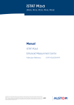
Micrologic 5.0 H
DB119909
E71927A
Selective protection + Idmtl, power measurements and additional protection
Micrologic 5.0 H
t
Idmtl
4260A
N 1 2 3
100
50
0
0
long time
Ir
.7
.6
.5
.4
tr
8
(s) 4
.9
12
16
.95 2
.98 1
20
24
1
.5
.8
x In
tsd
(s)
Ii
I
.3
.2
.1
2
on
I t
instantaneous
6 8 10
4
12
3
15
off
2
x In
.2
.1
0
off
delay
test
Micrologic 6.0 H
Y
X: type of protection
b 2 for basic protection
b 5 for selective protection
b 6 for selective + ground-fault protection
b 7 for selective + earth-leakage protection
Micrologic 6.0 H
t
t
DB119911
DB119909
Selective protection + Idmtl + ground-fault protection,
power measurements and additional protection
E71928A
E71926A
Ii
.4 .4 .3
setting
X
Isd
@ 6 Ir
short time
Isd
4
5
3
2.5
6
2
8
1.5
10
x Ir
Micrologic 5.0 H
Ir
Selective protection + Idmtl
alarm
Idmtl
4260A
2
I t on
N 1 2 3
100
Z
2
I t off
50
0
0
long time
Ir
.7
.6
.5
.4
tr
8
(s) 4
.9
12
16
.95 2
.98 1
20
24
1
.5
.8
x In
@ 6 Ir
short time
Isd
4
5
3
2.5
6
2
8
1.5
10
x Ir
tsd
on
setting
Ig
D
C
B
A
Ii
.4 .4 .3
.2
.3
.1
.2
.1 2 0
(s)
I t
instantaneous
4
3
off
6 8 10
12
15
off
2
x In
delay
Isd
Ii
0
I
Ig
I
Ground-fault protection
test
tg
E
Ir
Selective protection + Idmtl
alarm
.4 .4 .3
.2
.3
.1
.2
.1 2 0
(s)
F
G
H
J
on
I t
off
ground fault
Y: version number
Identification of the control-unit generation:
"0" signifies the first generation.
Micrologic 7.0 H
t
DB119913
DB119909
Selective protection + Idmtl + earth-leakage protection,
power measurements and additional protection
E71929A
Z: type of measurement
b A for "ammeter"
b P for "power meter"
b H for "harmonic meter"
b no indication = no measurements
Micrologic 7.0 H
Idmtl
4260A
t
N 1 2 3
100
50
0
0
long time
Ir
.7
.6
.5
.4
tr
8
(s) 4
.9
12
16
.95 2
.98 1
20
24
1
.5
.8
x In
@ 6 Ir
short time
Isd
4
5
3
2.5
6
2
8
1.5
10
x Ir
tsd
.4 .4 .3
.2
.3
.1
.2
.1 2 0
(s)
on
setting
I∆n
(A)
3
2
1
.5
5
alarm
I t
off
delay
(ms)
instantaneous
4
3
Isd
Ii
I
0
I∆n
I
Earth-leakage protection
6 8 10
12
15
off
2
x In
test
∆t
230
7
10
140
20
30
60
Ii
Ir
Selective protection
+ Idmtl
350
800
earth leakage
04443728AA - 01/2009
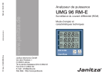
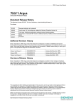
top fastener
terminal block for external connections
housing for battery
screw for long-time rating plug
long-time rating plug
cover opening point
protective cover
lead-seal fixture for protective cover
infrared link with communications interfaces
connection with circuit breaker
bottom fastener
E60235B
1
2
3
4
5
6
7
8
9
10
11
E60236A
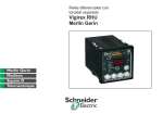
Presentation
Discovering Micrologic H
1
2
0P
5.
logic
Micro
3
9
alarm
Indications
time
tr
(s)
2
1
4
.5
8 12
16
20
24
at
6 Ir
4
5
7
10
6
11
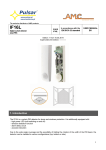
Micrologic 5.0 H
12
17
E60238A
LED indicating long-time tripping
LED indicating short-time or instantaneous tripping
LED indicating ground-fault or earth-leakage
tripping
LED indicating additional-protection or
auto-protection tripping
graphics display
button for reset of fault-trip LED reset
and battery test
8
E71930A
12
13
14
15
16
17
long
.8 .9
.7
.95
.6
.98
.5
1
.4 x In
Ir
18
19
20
21
22
23
13
14
Navigation
100
50
0
Micrologic 5.0 H control unit
E60239A
long-time current setting Ir
long-time tripping delay tr
short-time pickup Isd
short-time tripping delay tsd
instantaneous pickup Ii
ground-fault pickup Ig
ground-fault tripping delay tg
earth-leakage pickup I∆n
earth-leakage tripping delay ∆t
LED indicating an overload
test button for ground-fault and
earth-leakage protection
test connector
N 1 2 3
16
Adjustment dials
24
25
26
27
28
29
30
31
32
33
34
35
4260A
15
access button to the "Metering" menu (1)
access button to the "History, maintenance
and setup" menu (1)
access button to the "Protection" menu (1)
button used to scroll down or reduce
the displayed value
button used to scroll up or increase
the displayed value
button used to select or confirm a choice
long time
Ir
24
25
26
27
.7
.6
.5
.4
tr
8
(s) 4
.9
12
16
.95 2
.98 1
20
24
1
.5
.8
x In
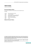
Micrologic 6.0 H control unit
33
alarm
tsd
(s)
.4 .4 .3
.3
.2
.1
2
on
setting
I t
Ii
25
.2
.1
0
off
instantaneous
6 8 10
4
12
3
15
off
2
x In
28
26
27
delay
long time
Ir
24
@ 6 Ir
short time
Isd
4
5
3
2.5
6
2
8
1.5
10
x Ir
E60240A
18
19
20
21
22
23
.7
.6
.5
.4
29
30
x In
tsd
.4 .4 .3
.2
.3
.1
.2
.1 2 0
(s)
on
setting
D
C
B
A
E
33
alarm
@ 6 Ir
short time
Isd
4
5
3
2.5
6
2
8
1.5
10
x Ir
Ig
35
tr
8
(s) 4
.9
12
16
.95 2
.98 1
20
24
1
.5
.8
I t
off
delay
instantaneous
4
3
6 8 10
12
15
off
2
x In
test
tg
F
G
H
J
Ii
.4 .4 .3
.2
.3
.1
.2
.1 2 0
28
34
(s)
on
I t
35
off
ground fault
E60241B
Micrologic 7.0 H control unit
(1) These buttons include a LED indicating the active menu.
long time
Ir
24
25
26
27
.7
.6
.5
.4
04443728AA - 01/2009
3
2
1
.5
5
33
alarm
@ 6 Ir
tsd
.4 .4 .3
.2
.3
.1
.2
.1 2 0
(s)
on
setting
(A)
32
x In
short time
Isd
4
5
3
2.5
6
2
8
1.5
10
x Ir
I∆n
31
tr
8
(s) 4
.9
12
16
.95 2
.98 1
20
24
1
.5
.8
I t
off
delay
(ms)
230
10
140
20
30
60
instantaneous
4
3
6 8 10
12
15
off
2
x In
test
∆t
7
Ii
28
34
350
800
35
earth leakage
Setting procedure
Dials
b Dials are used to set Micrologic H protection
thresholds and tripping delays for overloads, shortcircuits, ground faults and earth leakage.
b If the set thresholds are overrun, these protection
functions systematically trip the circuit breaker.
Settings using the dials
With the protective cover open, make all the necessary
settings for your control unit.
All fine adjustments are permanently stored in memory,
unless the setting is modified using the adjustment dial.
For remote settings using the communications option,
see the "Remote settings" section in the "Com setup"
menu under "History, maintenance and setup".
DB119914
logic
Micro
5.0
b Open the protective
cover.
logic
Micro
5.0
b Make the necessary settings using the dials
b The screen automatically displays the relevant curve
b Check the set value on the screen, in absolute value
in amperes (A) and in seconds (s).
Settings using the keypad
b The
and
buttons under the screen may be
used for fine adjustments of the settings made using
the dials.
b All the settings not available via the dials are made in
the same manner, using the keypad.
E60252B
Buttons
b Buttons on the keypad are used for fine adjustments
of the protection thresholds and tripping delays for
overloads, short-circuits, ground faults and earth
leakage. The value previously set using a dial
automatically becomes the maximum value for the
keypad settings.
b They may also be used to activate other factorydisabled protection functions available on Micrologic H.
These other protection functions are not accessible via
the dials.
DB119915
Discovering Micrologic H
logic
Micro
5.0
Caution!
A new overload (long-time) or short-circuit
(short-time and instantaneous) protection setting
made using one of the dials:
b deletes all the fine adjustments previously
made using the keypad for the overload
(long-time) and short-circuit (short-time and
instantaneous) protection
b does not affect the fine adjustments made
using the keypad for ground-fault and earthleakage protection
b does not affect any other settings made using
the keypad.
Similarly, a new ground-fault or earth-leakage
protection setting made using one of the dials:
b deletes all the fine adjustments previously
made using the keypad for the ground-fault and
earth-leakage protection
b does not affect the fine adjustments made
using the keypad for the overload (long-time) and
short-circuit (short-time and instantaneous)
protection
b does not affect any other settings made using
the keypad.
04443728AA - 01/2009
Setting procedure
With the protective cover closed, it is not possible to set
the protection functions. However, it is possible to set
metering functions and alarms, as well as view all
measurements, settings and histories.
View the settings and measurements
DB119916
E60254B
Discovering Micrologic H
logic
Micro
5.0
DB119917
b Close the protective
cover for the dials
b Access to the dials is
blocked and it is no longer
possible to make fine
adjustments using the
keypad
logic
Micro
04443728AA - 01/2009
logic
Micro
5.0
5.0
b If necessary, install a
lead seal to protect the
settings
b Settings may be
viewed at any time using
the keypad.
Caution!
If you notice that the tab on the back of the protective
cover has been broken off, contact the Schneider
Electric after-sales support department to replace the
cover.
Setting Micrologic 5.0 H
using the dials
Consider a 2000 A circuit breaker.
Set the thresholds
DB119918
DB119919
Discovering Micrologic H
Ir
In = 2000 A
long time
.7
.6
.5
.4
.8
x In
Ir = 0.5 x 2000 = 1000 A
.9
.95
.98
1
Isd = 2 x 1000 = 2000 A
short time
Isd
4
5
3
2.5
6
2
8
1.5
10
x Ir
1
Ii
Ii = 2 x 2000 = 4000 A
instantaneous
6 8 10
4
12
3
15
off
2
x In
setting
In 2000 A
In =
A
2000
Set the time delays
DB119910
See pages 22 and 24 for selection of the setting
ranges.
long time
tr
(s)
2
1
short time
4
.5
8
tr = 1 s
12
16
20
24
tsd = 0.2 s
@ 6 Ir
tsd
.4 .4 .3
.2
.3
.1
.2
.1 2 0
(s)
Time delays
I2t ON curve
t
t
t
Ir
Ir
I t
delay
off
I2t OFF curve
DB119923
I2t OFF curve
DB119922
Thresholds
I2t ON curve
DB119921
DB119920
on
t
tr
Isd
tr
Isd
tsd
Ii
0
Ir: LT threshold
Isd: ST pickup
Ii: Instantaneous pickup
tsd
Ii
I
0
I
0
I
0
I
tr: LT tripping delay
tsd: ST tripping delay
04443728AA - 01/2009
Setting Micrologic 6.0 H
using the dials
Consider a 2000 A circuit breaker.
Set the thresholds
DB119918
DB119924
Discovering Micrologic H
In = 2000 A
long time
Ir
.7
.6
.5
.4
.8
.9
.95
.98
1
x In
Ir = 0.5 x 2000 = 1000 A
short time
Isd
4
5
3
2.5
6
2
8
1.5
10
x Ir
1
D
C
B
A
In 2000 A
A
2000
E
Isd = 2 x 1000 = 2000 A
instantaneous
6 8 10
4
12
3
15
off
2
x In
setting
Ig
In =
Ii
Ii = 2 x 2000 = 4000 A
B
F
G
H
J
Ig = 640 A
ground fault
See pages 22 to 26 for selection of the setting ranges.
DB119925
Set the time delays
long time
tr
(s)
2
1
short time
4
.5
tsd
(s)
on
(s)
t
delay
on
2
I t
.2
.1
0
off
tg = 0.2 s
.2
.1
0
off
Ir
I2t OFF curve
t
t
DB119923
Ir
DB119922
t
2
I t
tsd = 0.2 s
Time delays
I2t ON curve
I2t OFF curve
DB119921
DB119920
Thresholds
I2t ON curve
@ 6 Ir
.4 .4 .3
.3
.2
.1
ground fault
tr = 1 s
12
16
20
24
.4 .4 .3
.3
.2
.1
tg
8
tr
tr
Isd
Isd
tsd
I
t
Ig
0
tr: LT tripping delay
tsd: ST tripping delay
I
t
0
DB119929
0
DB119928
t
I
DB119927
DB119926
0
Ir: LT threshold
Isd: ST pickup
Ii: Instantaneous pickup
tsd
Ii
Ii
I
t
Ig
tg
tg
0
I
Ig: ground-fault pickup
04443728AA - 01/2009
0
I
0
I
tg: ground-fault tripping delay
0
I
Setting Micrologic 7.0 H
using the dials
Consider a 2000 A circuit breaker.
Set the thresholds
DB119918
DB119930
Discovering Micrologic H
In = 2000 A
long time
Ir
.7
.6
.5
.4
.8
.9
.95
.98
1
x In
Ir = 0.5 x 2000 = 1000 A
short time
Isd
4
5
3
2.5
6
2
8
1.5
10
x Ir
1
I∆n
(A)
A
2000
5
Isd = 2 x 1000 = 2000 A
instantaneous
6 8 10
4
12
3
15
off
2
x In
setting
3
2
1
.5
In 2000 A
In =
Ii
Ii = 2 x 2000 = 4000 A
I∆n = 1 A
7
10
20
30
earth leakage
Set the time delays
long time
tr
(s)
2
1
short time
8
4
.5
tsd
@ 6 Ir
.4 .4 .3
(s)
.3
.2
.1
on
∆t
(ms)
tr = 1 s
12
16
20
24
2
I t
delay
230
tsd = 0.2 s
E60153A
DB119931
See pages 22 to 26 for selection of the setting ranges.
.2
.1
0
off
∆t = 140 ms
350
140
60
800
earth leakage
t
Ir
I2t OFF curve
t
DB119923
Ir
DB119922
t
Time delays
I2t ON curve
I2t OFF curve
DB119921
DB119920
Thresholds
I2t ON curve
t
tr
Isd
tr
Isd
tsd
Ii
t
I
0
I
0
tr: LT tripping delay
tsd: ST tripping delay
DB119933
DB119932
0
Ir: LT threshold
Isd: ST pickup
Ii: Instantaneous pickup
tsd
Ii
I
0
I
t
I∆n
∆t
0
I
I∆n: earth-leakage pickup
10
0
I
∆t: earth-leakage tripping
delay
04443728AA - 01/2009
Discovering Micrologic H
Selecting the type of neutral
protection
E51383A
Selection dial on four-pole circuit breakers
D+N/2
3
4P 3D
4P 4D
On four-pole circuit breakers, it is possible to select the type of neutral protection for
the fourth pole using the three-position dial on the circuit breaker:
b no neutral protection 4P 3D
b half neutral protection 3D + N/2
b full neutral protection 4P 4D
The factory default setting is 3D + N/ 2.
Caution!
With the 4P 3D setting, the current in the neutral must
not exceed the rated current of the circuit breaker.
04443728AA - 01/2009
11
Main menus
Discovering Micrologic H
The Micrologic H control unit offers access to the main screen and three menus:
b the main screen displaying the continuous measurement of the phase currents (I1,
I2, I3) and the neutral current (IN), if it exists
b the "Metering" menu
b the "History, maintenance and setup" menu
b the "Protection" menu.
E60101A
Main screen
4260A
1 2 3
100
As long as no functions are activated, Micrologic H
control units display in real time the current on the most
heavily loaded phase.
The number for that phase is presented in a square.
The current in the neutral is displayed if the neutral CT
is set as internal or external (see "Ineutral (A)" settings
in the "Current protection" menu).
50
0
"Metering", "History, maintenance and setup"
and "Protection" menus
When a menu button is pressed, a presentation screen
is displayed and the green LED on the button goes ON.
E71931B
b "Metering" menu
I
(A)
U
(V)
P
(kW)
E
(kWh)
v press the
screen
or
button to return to the main
v press the
button to return to the previous
screen
v whatever the screen displayed, if no further action is
taken, the system returns to the main screen after a
few minutes
v the LED goes OFF on exiting the menu.
Harmonic
armoniq.
12
04443728AA - 01/2009
Main menus
Discovering Micrologic H
E71711A
b "History, maintenance and setup" menu
v press the
screen
Event
history
Contacts
M2C / M6C
Micrologic
setup
or
button to return to the main
v press the
button to return to the previous
screen
v whatever the screen displayed, if no further action is
taken, the system returns to the main screen after a
few minutes
v the LED goes OFF on exiting the menu.
Metering
setup
Com.
setup
E71712A
b "Protection" menu
v press the
screen
Current
protection
or
button to return to the main
v press the
button to return to the previous
screen
v whatever the screen displayed, if no further action is
taken, the system returns to the main screen after a
few minutes
v the LED goes OFF on exiting the menu.
Voltage
protection
Other
protection
Load
shedding
I
Load
shedding
P
b Saving settings
E71657A
When a setting is made in any of the three menus, the
screen used to save the modification(s) may be
accessed by pressing one of the three buttons
,
Do you want
to save new
settings?
or
.
v select yes to save the modifications
v select no to cancel and maintain the previous
settings
v this screen remains displayed until yes or no are
selected.
no
yes
04443728AA - 01/2009
13
Discovering Micrologic H
Metering
Press the
button to select the "Metering" menu.
move the cursor down the screen or decrement a value.
select an option in a list, confirm a selection or the value of a setting.
indicates that the operator is in the "Metering" menu and returns
to the previous screen.
move the cursor up the screen or increment a value.
return to the main screen.
E71932B
Current measurements
I
(A)
U
(V)
P
(kW)
E
(kWh)
I
(A)
access to the following sections:
Instant.
Harmonic
I1, I2, I3, IN
I1, I2, I3, IN currents
(depending on the type of
system)
Max
Storing and reset of the
maximum instantaneous
currents
I1, I2, I3, IN
Demand current on the
phases I1, I2, I3 and on IN
(depending on the type of
system)
Max
Storing and reset of
the maximum demand
currents.
E71933B
Demand
I
(A)
U
(V)
P
(kW)
E
(kWh)
Harmonic
Voltage measurements
U
(V)
Instant.
Instantaneous phase-to-phase U12, U23, U31 and
phase-to-neutral V1N, V2N, V3N voltages
(depending on the type of system)
Average 3 Φ
Average voltage U average of the phase-to-phase
voltages.
Unbal 3 Φ
Unbalance voltage U unbal. of the phase-to-phase
voltages.
Phase
rotation
14
access to the following sections:
Phase sequence.
04443728AA - 01/2009
E71934B
Discovering Micrologic H
I
(A)
U
(V)
P
(kW)
E
Metering
Power measurements
P
(kW)
access to the following sections:
Instant.
P, Q, S,
(kWh)
Power
factor
Harmonic
Total active power P
Total reactive power Q
Total apparent power S
Power factor PF
Demand
P, Q, S
E71935B
Max
I
(A)
U
(V)
P
(kW)
E
(kWh)
Harmonic
Storing and reset of
the maximum demand power
values
Energy measurements
E
(kWh)
access to the following sections:
E total
Total active energy E.P
Total reactive energy E.Q
Total apparent energy E.S
E in
Positive component of:
b the total active energy E.P
b the total reactive energy E.Q
E out
Negative component of:
b the total active energy E.P
b the total reactive energy E.Q
Reset
Energy
04443728AA - 01/2009
Demand values for the:
b total active power P
b total reactive power Q
b total apparent power S
Reset all the energy values to zero
15
E71936B
Discovering Micrologic H
I
(A)
U
(V)
P
(kW)
E
Metering
Harmonic measurements
Harmonic
access to the following sections:
Waveform
(kWh)
Harmonic
I1, 2, 3
Waveform capture
for currents I1, I2 and I3
IN
Waveform capture
for the neutral current IN
U12, 23, 31
Waveform capture for
voltages U12, U23 and U31
Fundament.
Measurement of
the fundamental of currents
I1, I2, I3 and IN
I
(A)
U
(V)
P
(W)
I
(%)
U
(%)
I
(%)
U
(%)
Total harmonic distortion of
voltages U12, U23 and U31
and V1N, V2N and V3N
I (3, 5, 7,..., 31)
Amplitude spectrum of odd
current harmonics
up to H31
U (3, 5, 7,..., 31)
Amplitude spectrum of odd
voltage harmonics
up to H31
Measurement of
the fundamental of voltages
U12, U23 and U31
and V1N, V2N and V3N
Measurement of
the fundamental of active
power P, reactive power Q
and apparent power S.
THD
Total harmonic distortion
of currents I1, I2, I3 and IN
Total harmonic distortion
of voltages U12, U23 and
U31 and V1N, V2N
and V3N
thd
Total harmonic distortion
of currents I1, I2, I3 and IN
FFT
16
04443728AA - 01/2009
E71937B
Discovering Micrologic H
U
(V)
P
(kW)
E
(kWh)
Metering
Frequency measurement
F
(Hz)
access to the frequency measurement
Harmonic
F
(Hz)
04443728AA - 01/2009
17
Discovering Micrologic H
History, maintenance
and setup
Press the
E71711A
Event
history
Contacts
M2C / M6C
move the cursor down the screen or decrement a value.
move the cursor up the screen or increment a value.
select an option in a list, confirm a selection or the value of a setting.
indicates that the operator is in the "History, maintenance and setup" menu
and returns to the previous screen.
return to the main screen.
Event history
Event
history
The last ten faults recorded
Metering
setup
Alarm
history
The last ten alarms recorded
Com.
setup
Operation
counter
Number of operations (opening or closing)
Contact
wear
Wear of the circuit-breaker main contacts
Event
history
Contacts
M2C / M6C
Micrologic
setup
M2C / M6C Contacts
Contacts
M2C / M6C
Alarm
type
Metering
setup
Setup
Com.
setup
Reset
18
access to the following sections:
Trip
history
Micrologic
setup
E71713A
button to select the "History, maintenance and setup" menu.
access to the following sections:
Assignment of a protection alarm to an M2C or an
M6C contact
Latching mode for each M2C or M6C contact
Reset of the M2C or M6C contacts
04443728AA - 01/2009
E71714A
Discovering Micrologic H
Event
history
Contacts
M2C / M6C
Micrologic
setup
History, maintenance
and setup
Micrologic setup
Micrologic
setup
Language
Setting of the date and time
Date / time
Com.
setup
Breaker
selection
Indication of the circuit-breaker type
Power
sign
Setting the power sign
System
frequency
E71715A
Selection of the display language
Metering
setup
VT ratio
Event
history
Contacts
M2C / M6C
Micrologic
setup
Com.
setup
Event
history
Contacts
M2C / M6C
Select of the primary and secondary voltages on the
instrument transformer
Indication of the rated system frequency
Metering setup
Metering
setup
access to the following sections:
System
type
b 3 phases, 3 wires, 3 CTs: method using two
wattmeters
b 3 phases, 4 wires, 3 CTs: method using three
wattmeters
b 3 phases, 4 wires, 4 CTs: method using three
wattmeters with measurement of the neutral current.
Current
demand
Selection of the calculation method and setting of the
time interval for the calculation
Power
demand
Selection of the calculation method and setting of the
parameters for the calculation
Sign
convention
Setting of the sign convention for the power factor
and reactive power, i.e. IEEE, IEEE alternate or IEC
(see page 106 to determine the sign convention)
Metering
setup
E71716A
access to the following sections:
COM communications-option setup
Com.
setup
access to the following sections:
Com.
parameter
Setting of parameters for the COM communications
option (address, baud rate, parity)
Metering
setup
Remote
settings
Authorisation of access to settings via
the COM communications option.
Com.
setup
Remote
control
Authorisation of access to the circuit-breaker ON
and OFF commands via the COM communications
option.
Micrologic
setup
04443728AA - 01/2009
19
Discovering Micrologic H
Protection
Press the
move the cursor down the screen or decrement a value
move the cursor up the screen or increment a value
select an option in a list, confirm a selection or the value of a setting
indicates that the operator is in the "Protection" menu and returns
to the previous screen
E71712A
button to select the "Protection" menu.
return to the main screen
Current protection
Current
protection
Voltage
protection
Other
protection
I
(A)
Fine settings of the long-time I2t, short-time and
instantaneous protection functions
(A)
Fine settings of the long-time Idmtl,
short-time and instantaneous protection functions
(A)
Fine settings of the:
b ground-fault (Micrologic 6.0 H)
b earth-leakage (Micrologic 7.0 H) protection functions
Load
shedding
I
Idmtl
Load
shedding
P
I
Ineutral (A)
Selection of the type of neutral
sensor and type of neutral protection
I
Setting of the I
Alarm
Iunbal
20
access to the following sections:
Current
protection
(%)
alarm
Setting of the current-unbalance protection I unbal
I1 max (A)
Setting of the maximum-current protection I1 max
I2 max (A)
Setting of the maximum-current protection I2 max
I3 max (A)
Setting of the maximum-current protection I3 max
IN max (A)
Setting of the maximum-current protection IN max
04443728AA - 01/2009
E71719A
Discovering Micrologic H
Voltage protection
Current
protection
E71720A
Load
shedding
Umin
(V)
I
Umax
(V)
P
Uunbal (%)
Other protection
Current
protection
Other
protection
Voltage
protection
Other
protection
Load
shedding
E71721A
Load
shedding
rPmax (W)
I
Fmin (Hz)
P
Fmax (Hz)
Phase
rotation
Current
protection
Setting of the minimum-voltage protection U min.
Setting of the maximum-voltage protection U max.
Setting of the voltage-unbalance protection U unbal.
access to the following sections:
Setting of the reverse-power protection rP max
Setting of the minimum-frequency protection F min
Setting of the maximum-frequency protection F max
Setting of the phase-rotation protection
Load shedding depending on current
Voltage
protection
Other
protection
E71722A
access to the following sections:
Voltage
protection
Voltage
protection
Other
protection
Load
shedding
Protection
Load
shedding
Load
shedding
I
Load
shedding
P
I
Access to load shedding and reconnection
depending on current
Load shedding depending on power
Current
protection
Load
shedding
Voltage
protection
Other
protection
Load
shedding
I
Load
shedding
P
04443728AA - 01/2009
P
Access to load shedding and reconnection
depending on power
21
Current protection
Overview of functions
I2t long-time protection
For the default values, the setting ranges, increment
steps and setting accuracies, see the technical
appendix.
The long-time protection function protects cables against overloads. This function is
based on true rms measurements.
It is possible to select either I2t long-time protection or Idmtl long-time protection.
I2t long-time protection
Long-time current setting Ir and standard tripping delay tr
Micrologic control unit Accuracy
Current setting
tripping betweeen 1.05 and 1.20 Ir
Time setting
Time delay (s)
Ir = In (*) x …
tr at 1.5 x Ir
tr at 6 x Ir
tr at 7.2 x Ir
0 to -30%
0 to -20%
0 to -20%
5.0 H, 6.0 H and 7.0 H
0.4
0.5
0.6
0.7
0.8
other ranges or disable by changing rating plug
0,5
1
2
4
8
12.5
25
50
100
200
0.7 (1)
1
2
4
8
0.7 (2)
0.69
1.38
2.7
5.5
0.9
0.95
0.98
1
12
300
12
8.3
16
400
16
11
20
500
20
13.8
24
600
24
16.6
(*) In: circuit breaker rating
(1) 0 to -40%
(2) 0 to -60%
b It is possible to enhance the Ir setting accuracy (reduced range) or disable the
long-time protection function by using a different long-time rating plug.
See the technical appendix "Changing the long-time rating plug".
Thermal memory
b The thermal memory continuously accounts for the amount of heat in the cables,
both before and after tripping, whatever the value of the current (presence of an
overload or not). The thermal memory optimises the long-time protection function of
the circuit breaker by taking into account the temperature rise in the cables.
b The thermal memory assumes a cable cooling time of approximately 15 minutes.
22
04443728AA - 01/2009
Current protection
Overview of functions
Idmtl long-time protection
Idmtl Protection
Long-time current setting Ir and Idmtl tripping delay tr
Micrologic control unit
Current setting
Ir = In (*) x …
tripping between 1.05 and 1.20 Ir
Accuracy
Time setting
DT
Time delay (s)
5.0 H, 6.0 H and 7.0 H
0.4
0.5
0.6
0.7
0.8
other ranges or disable by changing rating plug
0.9
0.95
0.98
1
0,5
1
2
4
8
12
16
20
24
tr at 1.5 x Ir
tr at 6 x Ir
tr at 7.2 x Ir
tr at 10 x Ir
0 to -20%
0 to -20%
0 to -20%
0 to -20%
0.53
0.53
0.53
0.53
1
1
1
1
2
2
2
2
4
4
4
4
8
8
8
8
12
12
12
12
16
16
16
16
20
20
20
20
24
24
24
24
tr at 1.5 x Ir
tr at 6 x Ir
tr at 7.2 x Ir
tr at 10 x Ir
0 to -30%
0 to -20%
0 to -20%
0 to -20%
1.9
0.5
0.7 (1)
0.7 (2)
3.8
1
0.88
0.8
7.6
2
1.77
1.43
15.2
4
3.54
2.86
30.4
8
7.08
5.73
45.5
12
10.6
8.59
60.7
16
14.16
11.46
75.8
20
17.7
14.33
91
24
21.2
17.19
tr at 1.5 x Ir
tr at 6 x Ir
tr at 7.2 x Ir
tr at 10 x Ir
0 to -30%
0 to -20%
0 to -20%
0 to -20%
3.6
0.5
0.7 (1)
0.7 (2)
7.2
1
0.81
0.75
14.4
2
1.63
1.14
28.8
4
3.26
2.28
57.7
8
6.52
4.57
86.5
12
9.8
6.86
115.4
16
13.1
9.13
144.2
20
16.34
11.42
173.1
24
19.61
13.70
tr at 1.5 x Ir
tr at 6 x Ir
tr at 7.2 x Ir
tr at 10 x Ir
0 to -30%
0 to -20%
0 to -20%
0 to -20%
12.5
0.7 (1)
0.7 (2)
0.7 (2)
25
1
0.69
0.7 (1)
50
2
1.38
0.7 (1)
100
4
2.7
1.41
200
8
5.5
2.82
300
12
8.3
4.24
400
16
11
5.45
500
20
13.8
7.06
600
24
16.6
8.48
tr at 1.5 x Ir
tr at 6 x Ir
tr at 7.2 x Ir
tr at 10 x Ir
0 to -30%
0 to -20%
0 to -20%
0 to -20%
164.5
0.7 (1)
0.7 (2)
0.7 (2)
329
1
0.7 (1)
0.7 (2)
658
2
1.1 (1)
0.7 (1)
1316
4
1.42
0.7 (1)
2632
8
3.85
1.02
3950
12
5.78
1.53
5265
16
7.71
2.04
6581
20
9.64
2.56
7900
24
11.57
3.07
SIT
Time delay (s)
VIT
Time delay (s)
EIT
Time delay (s)
HVF
Time delay (s)
(*) In: circuit breaker rating
(1) 0 to -40 %
(2) 0 to -60 %
b These curves with different slopes are used to improve:
v discrimination with fuses positioned upstream (HV) and/or downstream
v protection for certain types of loads
b Five types of curves are available:
v DT: definite time curve
v SIT: standard inverse time curve (I0.5t)
v VIT: very inverse time curve (It)
v EIT: extremely inverse time curve (I2t)
v HVF: compatible with high-voltage fuses (I4t).
b Neutral protection
Overload protection (long time) for the neutral is disabled if the Idmtl protection
function is selected. However, the short-circuit protection (short time and
instantaneous) remains operational.
b Intermittent overloads
As long as the Micrologic H control unit remains supplied with power, the effects of
intermittent overloads on cables are calculated. If power is cut, temperature rise in
cables is not calculated.
b Circuit-breaker thermal limit
For certain settings, the Idmtl curves may be limited by the I2t curve when the tripping
delay tr is set to 24 seconds or by its thermal memory. The maximum I2t curve
remains active for the phases and the neutral even when the Idmtl curves are
activated.
04443728AA - 01/2009
23
Overview of functions
Current protection
Short-time and instantaneous protection
For the default values, the setting ranges, increment
steps and setting accuracies, see the technical
appendix.
Short-time protection
b The short-time protection function protects the distribution system against
impedant short-circuits
b The short-time tripping delay and the I2t ON and I2t OFF options can be used to
ensure discrimination with a downstream circuit breaker
b This function carries out true rms measurements.
b Use of I2t curves with short-time protection:
v I2t OFF selected: the protection function implements a constant time curve
v I2t ON selected: the protection function implements an I2t inverse-time curve up to
10 Ir. Above 10 Ir, the time curve is constant.
For the characteristics and external wiring of the zone
selective interlocking function, see the technical
appendix on "Zone selective interlocking".
b Zone selective interlocking (ZSI)
The short-time and ground-fault protection functions enable time discrimination by
delaying the upstream devices to provide the downstream devices the time required
to clear the fault. Zone selective interlocking can be used to obtain total
discrimination between circuit breakers using external wiring.
b Intermittent faults are taken into account by Micrologic H and may lead to shorter
tripping times than those set.
Short-time pickup Isd and tripping delay tsd
Micrologic control unit
Pickup
Time delay (ms)
at 10 Ir
I2t On or
I2t Off
Isd = Ir x ... accuracy ± 10 %
setting
tsd (max resettable time)
tsd (max break time)
5.0 H, 6.0 H and 7.0 H
1.5
I2t Off
I2t On
20
80
2
0
80
140
2.5
0.1
0.1
140
200
3
0.2
0.2
230
320
4
0.3
0.3
350
500
5
0.4
0.4
6
8
10
If the "without long-time protection" plug is used and the long-time protection function
is disabled, the short-time pickup Isd is automatically multiplied by In instead of Ir as
is the standard case.
Instantaneous protection
b The instantaneous-protection function protects the distribution system against
solid short-circuits. Contrary to the short-time protection function, the tripping delay
for instantaneous protection is not adjustable. The tripping order is sent to the circuit
breaker as soon as current exceeds the set value, with a fixed time delay of 20
milliseconds.
b This function carries out true rms measurements.
Instantaneous pickup Ii
Micrologic control unit
Pickup
Ii = In (*) x ... accuracy ± 10 %
5.0 H, 6.0 H and 7.0 H
2
3
4
6
8
10
12
15
OFF
(*) In: circuit-breaker rating
b Circuit breakers have two types of instantaneous protection:
v adjustable instantaneous protection Ii
v self-protection.
Depending on the circuit breaker, the OFF position corresponds to
the self-protection pickup.
24
04443728AA - 01/2009
Overview of functions
Current protection
Neutral protection
For the default values, the setting ranges, increment
steps and setting accuracies, see the technical
appendix.
Three-pole circuit breakers
Protection of the neutral is possible on a three-pole circuit breaker by connecting an
external sensor.
Settings are made using the
and
buttons on the control unit.
Micrologic control unit
Setting
Type of neutral
No neutral protection
Half neutral protection
Full neutral protection
Oversized neutral protection
5.0 H, 6.0 H and 7.0 H
OFF
N/2
N
1.6xN
Description
The distribution system does not require protection of the neutral
conductor.
The cross-sectional area of the neutral conductor is half that of the
phase conductors.
b The long-time current setting Ir for the neutral is equal to half the
setting value
b The short-time pickup Isd for the neutral is equal to half the
setting value
b The instantaneous pickup Ii for the neutral is equal to the setting
value
b For ground-fault protection (Micrologic 6.0 P), pickup Ig for the
neutral is equal to the setting value.
The cross-sectional area of the neutral conductor is equal to that of
the phase conductors.
b The long-time current setting Ir for the neutral is equal to the
setting value
b The short-time pickup Isd for the neutral is equal to the setting value
b The instantaneous pickup Ii for the neutral is equal to the setting
value
b For ground-fault protection (Micrologic 6.0 P), pickup Ig for the
neutral is equal to the setting value.
In installations with a high level of third-order harmonic currents (or
multiples thereof), the current in the neutral conductor may exceed
that of the phase currents under steady-state conditions
b The long-time current setting Ir for the neutral is 1.6 times that of
the setting value
b The short-time pickup Isd for the neutral is 1.6 times that of the
setting value, but may not exceed 10 In to limit transients and selfprotect the installation
b The instantaneous pickup Ii for the neutral is equal to the setting
value
b For ground-fault protection (Micrologic 6.0 P), pickup Ig for the
neutral is equal to the setting value.
Four-pole circuit breakers
The initial protection setting is made using the dial on the neutral pole of the circuit
breaker.
The
and
buttons on the control unit may then be used for a more precise
setting. The dial setting constitutes the upper limit for adjustments using the keypad.
Micrologic control unit
Setting
Type of neutral
No neutral protection
Half neutral protection
Full neutral protection
04443728AA - 01/2009
5.0 H, 6.0 H and 7.0 H
OFF
N/2
N
Description
The distribution system does not require protection of the neutral
The cross-sectional area of the neutral conductor is half that of the
phase conductors.
b The long-time current setting Ir for the neutral is equal to half the
setting value
b The short-time pickup Isd for the neutral is equal to half the
setting value
b The instantaneous pickup Ii for the neutral is equal to the setting
value
The cross-sectional area of the neutral conductor is equal to that of
the phase conductors.
b The long-time current setting Ir for the neutral is equal to the
setting value
b The short-time pickup Isd for the neutral is equal to the setting value
b The instantaneous pickup Ii for the neutral is equal to the setting
value.
25
Overview of functions
Current protection
Ground-fault and earth-leakage
protection
For the default values, the setting ranges, increment
steps and setting accuracies, see the technical
appendix.
Ground-fault protection on Micrologic 6.0 H
b An ground fault in the protection conductors can provoke local temperature rise at
the site of the fault or in the conductors. The purpose of the ground-fault protection
function is to eliminate this type of fault.
b There are two types of ground-fault protection.
Type
Description
Residual
Source Ground Return
b The function determines the zero-phase sequence current, i.
e. the vector sum of the phase and neutral currents (depending
on the type of installation)
b Using a special external sensor, this function directly
measures the fault current returning to the transformer via the
earth cable
b It detects faults both upstream and downstream of the circuit
breaker
b The maximum distance between the sensor and the circuit
breaker is ten metres.
b Ground-fault and neutral protection are independent and can therefore be
combined.
Ground-fault pickup Ig and tripping delay tg
The pickup and tripping-delay values can be set independently and are identical for
both the residual and "source ground return" ground-fault protection functions.
Micrologic control unit
Pickup
Ig = In (*) x ... accuracy ±10 %
Time delay (ms)
at In or 1200 A
I2t On or
I2t Off
In y 400 A
400 A < In y 1200 A
In > 1200 A
settings
I2t Off
I2t On
tg (max resettable time)
tg (max. break time)
6.0 H
A
0.3
0.2
500 A
I2t Off
20
80
B
0.3
0.3
640 A
0
0.1
80
140
C
0.4
0.4
720 A
0.1
0.2
140
200
D
0.5
0.5
800 A
0.2
0.3
230
320
E
0.6
0.6
880 A
0.3
0.4
350
500
F
0.7
0.7
960 A
0.4
G
0.8
0.8
1040 A
H
0.9
0.9
1120 A
J
1
1
1200 A
(*) In: circuit-breaker rating
Earth-leakage protection on sur Micrologic 7.0 H
b The earth-leakage protection function primarily protects people against indirect
contact because an earth-leakage current can provoke an increase in the potential of
the exposed conductive parts. The earth-leakage pickup value I∆n is displayed
directly in amperes and the tripping delay follows a constant-time curve.
b An external rectangular sensor is required for this function
b This function is inoperative if the long-time rating plug is not installed
v q Protected against nuisance tripping
v kDC-component withstand class A up to 10 A.
b If the optional external voltage-measurement input is used, a 24 V DC external
power supply must be connected to Micrologic H (terminals F1-, F2+).
Pickup value I∆n and tripping delay ∆t
Micrologic control unit
Pickup (A)
Time delay (ms)
settings
26
I∆n accuracy 0 to -20 %
∆t (max resettable time)
∆t (max. break time)
7.0 H
0.5
1
2
3
5
60
140
140
200
230
320
350
500
800
1000
7
10
20
30
04443728AA - 01/2009
Current protection
Overview of functions
I t Alarm, current unbalance, maximum
current
Operating principle
For the pickup and dropout thresholds and time delays,
see the technical appendix.
DB119995
protection tripped by a maximum value
1: pickup threshold
2: pickup time delay
3: dropout threshold
4: dropout time delay
b
v
v
v
v
b
For protection tripped by a maximum value, it is possible to set:
a pickup threshold (1) that activates an alarm, a contact and/or tripping
a pickup time delay (2) that steps in when the pickup threshold (1) is reached
a dropout threshold (3) corresponding to deactivation of the alarm and/or contact
a dropout time delay (4) that steps in when the dropout threshold (3) is reached
The dropout threshold is always less than or equal to the pickup threshold.
I t Alarm
b The alarm function is tripped by the rms value of an earth-leakage current
b This alarm signals an earth-leakage current under the pickup value and does not
produce circuit-breaker tripping.
Current-unbalance protection I unbal
DB119996
b This protection is activated by an adjustable level of unbalance between the RMS
values of the three phase currents.
I
E max
I avg
0
I1
I2
I3
b From:
v I avg is the average value of the rms currents of the
three phases
I avg = I1 + I2 + I3
3
v E max is the maximum difference between the
current of each phase and I avg
b Micrologic H uses the two values above to calculate
the current unbalance:
E max
I unbal =
I avg
Maximum-current protection per phase Imax
b Protection values may be set for each of the following currents:
v I1 max: maximum current on phase 1
v I2 max: maximum current on phase 2
v I3 max: maximum current on phase 3
v IN max: maximum current in the neutral
b This function calculates the rms demand value of the current for the given phase
(I1, I2, I3) or the neutral (IN), over a sliding time interval.
The time interval is the same as that for the calculation of the demand currents in the
"Metering" menu.
Settings are made in the "Metering setup" menu.
Note:
IN max protection does not take into account the neutral-protection setting (N, N/2, 1.6 x N, OFF).
04443728AA - 01/2009
27
Voltage protection
Overview of functions
Minimum voltage, maximum voltage,
voltage unbalance
Operating principle
protection tripped
by a minimum value
protection tripped
by a maximum value
t
t
DB119997
DB119946
For the pickup and dropout thresholds and time delays,
see the technical appendix.
1
3
3
2
1
4
4
0
U min
2
0
U max
U unbal.
1: pickup threshold
2: pickup time delay
3: dropout threshold
4: dropout time delay
b For protection tripped by a minimum or maximum value, it is possible to set:
v a pickup threshold (1) that activates an alarm, a contact and/or tripping
v a pickup time delay (2) that steps in when the pickup threshold (1) is reached
v a dropout threshold (3) corresponding to deactivation of the alarm and/or contact
v a dropout time delay (4) that steps in when the dropout threshold (3) is reached
b For protection tripped by a minimum value, the dropout threshold is always greater
than or equal to the pickup threshold
b For protection tripped by a maximum value, the dropout threshold is always less
than or equal to the pickup threshold
b If both the minimum and maximum protection functions are activated at the same
time, the minimum threshold is automatically limited to the value of the maximum
and vice versa.
Minimum-voltage protection U min
If the voltage protection functions are activated and the
voltage measurement inputs are still energised, it is
impossible to reset and close the circuit breaker.
b This function calculates the minimum rms value of the three phase-to-phase
voltages
b Protection is activated when at least one of the three phase-to-phase voltages
(U12, U23, U31) is below the threshold set by the user
b This protection function does not detect phase failure.
Maximum-voltage protection U max
b This function calculates the maximum rms value of the three phase-to-phase
voltages
b Protection is activated when the three phase-to-phase voltages (U12, U23, U31)
are simultaneously above the threshold set by the user.
Voltage-unbalance protection U unbal
DB119998
This protection is activated by an adjustable level of unbalance between the rms
values of the three phase-to-phase voltages.
This function calculates the rms value of the unbalance between the three phase-tophase voltages.
U
E max
U avg
0
U12
U23
U31
b From:
v U avg is the average value of the rms voltages of the
three phases
U avg = U12 + U23 + U31
3
v E max: is the maximum difference between the
voltage of each phase and U avg
b Micrologic H uses the two values above to calculate
the voltage unbalance:
U unbal =
28
E max
U avg
04443728AA - 01/2009
Other protection
Overview of functions
Reverse power, min. frequency,
max. frequency, phase rotation
Operating principle
protection tripped
by a minimum value
protection tripped
by a maximum value
t
t
DB119950
DB119949
For the pickup and dropout thresholds and time delays,
see the technical appendix.
1
2
3
3
4
4
0
F min
1
2
0
F max
rP max
1: pickup threshold
2: pickup time delay
3: dropout threshold
4: dropout time delay
b For protection tripped by a minimum or maximum value, it is possible to set:
v a pickup threshold (1) that activates an alarm, a contact and/or tripping
v a pickup time delay (2) that steps in when the pickup threshold (1) is reached
v a dropout threshold (3) corresponding to deactivation of the alarm and/or contact
v a dropout time delay (4) that steps in when the dropout threshold (3) is reached
b For protection tripped by a minimum value, the dropout threshold is always greater
than or equal to the pickup threshold
b For protection tripped by a maximum value, the dropout threshold is always less
than or equal to the pickup threshold
b If both the minimum and maximum protection functions are activated at the same
time, the minimum threshold is automatically limited to the value of the maximum
and vice versa.
Reverse-power protection rP max
b This function calculates the value of the total active power on the three phases
b The function is activated when the total active power of the three phases flows in
the direction opposite that set by the user is greater than the pickup threshold (1) for
a time greater than the time delay (2).
Note:
the direction of flow is set by the user in the "Power sign" section of the "Micrologic setup" menu
under "History, maintenance and settings".
b + corresponds to the normal direction of flow, i.e. from the top terminals on the circuit breaker
to the bottom terminals
b - is the opposite.
If the voltage protection functions are activated and the
voltage measurement inputs are still energised, it is
impossible to reset and close the circuit breaker.
Minimum and maximum-frequency protection
F min. and F max
These functions monitor the value of the frequency on the distribution system.
Phase-rotation alarm
This alarm is activated if two of the three phases are inverted.
Note:
the alarm is activated following a fixed 300-millisecond time delay. If one of the phases is absent,
the alarm will not operate. If the 400 Hz frequency is set, the alarm cannot be activated.
04443728AA - 01/2009
29
Overview of functions
Load shedding
and reconnection
For the pickup and dropout thresholds and time delays,
see the technical appendix.
Load shedding and reconnection depending on current
DB119999
The pickup curve for load shedding and reconnection depending on current is
parallel to the LT I2t and Idmtl curves. If a "without long-time protection" rating plug is
installed, the load shedding/reconnection function based on current cannot be
activated.
b I2t protection: the neutral is taken into account
b Idmtl: the neutral is not taken into account.
This function does not trip the circuit breaker, but can be used to set off an alarm
linked to an M2C or M6C contact (disconnection and reconnection of non-priority
loads).
The load-shedding and reconnection function is determined by thresholds and time
delays.
t
Long-time
protection
curve
3
1
4
2
0
I
1: pickup threshold
2: pickup time delay
3: dropout threshold
4: dropout time delay
The pickup threshold is always greater than or equal to the dropout threshold.
Load shedding and reconnection depending on power
DB119952
Load shedding and reconnection depending on power calculates the total active
power on the three phases. This function does not trip the circuit breaker, but can be
used to set off an alarm linked to an M2C or M6C contact (disconnection and
reconnection of non-priority loads).
The load-shedding and reconnection function is determined by thresholds and time
delays.
t
3
4
1
2
0
P
1: pickup threshold
2: pickup time delay
3: dropout threshold
4: dropout time delay
The pickup threshold is always greater than or equal to the dropout threshold.
30
04443728AA - 01/2009
Measurements
Overview of functions
Current and voltage
Instantaneous current
For the setting ranges and measurement accuracies,
see the technical appendix.
Micrologic H control units offer two, non-exclusive measurement possibilities.
b On the bargraph display on the main screen
The instantaneous current of the most heavily loaded phase is automatically
displayed in amperes for phases 1, 2, 3 and the neutral (depending on the neutral
protection settings). The bargraph indicates the percent load of the
three phases.
b In the I inst. section of the instantaneous currents
v display in amperes of the instantaneous currents I (rms) on phases I1, I2 and I3
and the neutral current IN, the ground-fault current Ig (Micrologic 6.0 H), the
earth-leakage current I∆n (Micrologic 7.0 H)
v the maximum instantaneous currents are displayed and stored in memory
v the stored maximums can be reset at any time.
Demand current
b Display of the demand current on phases I1, I2, I3 and the neutral IN (depending
on the type of distribution system)
b Selection of the demand calculation method
b Display of the interval over which the value is calculated
b The maximum demand values are displayed and stored in memory
b The stored maximums can be reset at any time.
Note:
the calculation method, the type of calculation window (fixed or sliding) and its duration may be
set in the "Metering setup" menu under "History, maintenance and setup".
Phase-to-neutral and phase-to-phase voltages
Micrologic H offers different voltage measurements:
b phase-to-phase voltages (rms) between phases U12, U23 and U31,
displayed in volts
b phase-to-neutral voltages (rms) between the phases and the neutral V1N, V2N
and V3N, displayed in volts.
Average voltage
Average Uavg of the instantaneous voltages between phases U12, U23 and U31.
Phase rotation
Displays the phase sequence.
Voltage unbalance
To display the phase-to-neutral voltages, select the "3Φ
4w 4CT" option in "System type" in the "Metering
setup" menu under "History, maintenance and setup".
DB119998
Display of the unbalance Uunbal between the three phase-to-phase voltages,
displayed as a percentage.
U
E max
U avg
0
U12
U23
U31
b From:
v U avg is the average value of the rms voltages of the
three phases
U avg = U12 + U23 + U31
3
v E max is the maximum difference between the
voltage of each phase and U avg
b Micrologic H uses the two values above to calculate
the voltage unbalance
U unbal =
04443728AA - 01/2009
E max
U avg
31
Overview of functions
Measurements
Power, energy and frequency
For the setting ranges and measurement accuracies,
see the technical appendix.
Instantaneous power and power factor
Micrologic H offers a number of different measurements.
b Total power measurements:
v instantaneous active power P in kW
v instantaneous reactive power Q in kvar
v instantaneous apparent power S in kVA
b Measurement of the power factor PF.
Demand power
b Display of the demand values for the active power P, reactive power Q and
apparent power S
b Selection of the demand calculation method
b Display of the interval over which the value is calculated
b The maximum demand values are displayed and stored in memory
b The stored maximums can be reset at at any time.
Note:
b the calculation method, the type of calculation window (fixed or sliding) and its duration may
be set in the "Metering setup" menu under "History, maintenance and setup".
b the synchronisation function (Synchro.Com) is available only with the COM communication
option; with this function, the demand power is determined on the basis of a signal synchronised
by the communication module.
b these settings apply to all demand powers (active power P, reactive power Q and apparent
power S). If the settings are modified, the demand values are systematically recalculated.
Energy
Micrologic H offers a number of different measurements:
b total energy:
v total active energy E.P in kWh
v total reactive energy E.Q in kvarh
v total apparent energy E.S in kVAh
b energy consumed (Energy in), positively incremented:
v active energy E.P in kWh
v reactive energy E.Q in kvarh
b energy supplied (Energy out), negatively incremented:
v active energy E.P in kWh
v reactive energy E.Q in kvarh
b energy values can be reset.
Note:
b the Energy in and Energy out values are incremented according to the power sign set in the
"Metering setup" menu under "History, maintenance and setup".
b as standard, the total calculated energy values are "absolute total values".
They represent the sum of the energy in and out values:
v EP = Σ EP in + Σ EP out
v EQ = Σ EQ in + Σ EQ out
b as an option (access exclusively via the COM communications option), energy can be
calculated algebraically:
v EP = Σ EP in - Σ EP out
v EQ = Σ EQ in - Σ EQ out
These values are called "signed" energies.
Frequency
The frequency of the distribution system is displayed in Hz.
32
04443728AA - 01/2009
Overview of functions
Harmonic measurements
Origin and effects
Harmonics represent the most common power problem encountered in today’s
electrical installations.
When harmonics are present, the current or voltage waveform is distorted, i.e. it is no
longer perfectly sinusoidal.
A distorted current or voltage waveform disturbs the distribution of electrical power
and power quality is not optimum.
Definition of harmonics
A periodic signal is a combination of:
v the original sinusoidal signal at the fundamental frequency
v other sinusoidal signals (the harmonics) with frequencies that are whole-number
multiples of the fundamental frequency
v a DC component, where applicable.
Any periodic signal can therefore be represented as the sum of a number of terms:
∞
y(t) = Yo + Σ Yn
DB120067
n=1
2 sin(nωt - ϕn)
Fundamental
50 Hz
I1
where:
b Yo is the value of the DC component (generally equal to zero and considered as
such hereinafter)
b Yn is the rms value of the nth harmonic
b ω is the angular frequency of the fundamental
b ϕn is the phase displacement of the harmonic component at t = 0.
Harmonic
3 (150 Hz)
I3
A harmonic of order n, referred to as the nth harmonic, is the sinusoidal component
of a signal with a frequency that is n times higher than the fundamental frequency.
Harmonic
5 (250 Hz)
I5
Harmonic
7 (350 Hz)
Harmonic
9 (450 Hz)
I7
I peak
Total
I rms
I9
For example, the current and voltage waveforms distributed on the European
electrical power grid have the following characteristics:
b the fundamental frequency is 50 hertz (Hz)
b the 2nd harmonic has a frequency of 100 Hz
b the 3rd harmonic has a frequency of 150 Hz
b the 4th harmonic has a frequency of 200 Hz
b…
A distorted waveform is the result of superimposing the various harmonics on the
fundamental.
The figure opposite shows a current distorted by harmonics.
04443728AA - 01/2009
33
Harmonic measurements
Overview of functions
DB120068
Origin and effects
Standby generator
set
Ina
Rectifiers,
Arc furnaces,
Welding machines
Inb
Variable-speed
drives
Ind
Fluorescent or
discharge lamps
G
Power-factor
correction
HV/LV
A
∑ In and
distorted
voltage
Harmonic disturbances
transmitted to distribution
system and other users
Ine
(do not cause
harmonics)
Devices using rectified
current (televisions,
computers, etc.)
Linear loads
Origin of harmonics
Harmonics are caused by non-linear loads.
A load is said to be non-linear when the current that it draws does not have the
same waveform as the voltage. Typical examples of non-linear loads are those using
power electronics. Such loads are increasingly numerous and their share in overall
electrical consumption is growing.
Examples are:
b industrial equipment including welding machines, arc furnaces, induction
furnaces, rectifiers, etc.
b variable speed drives for asynchronous or DC motors
b office equipment including computers, photocopy machines, fax machines, etc.
b household equipment including televisions, microwave ovens, neon lighting,
UPSs, etc.
Non-linear phenomena may also be caused by the saturation of transformers and
other equipment.
Effects of harmonics
The flow of harmonics in distribution systems can cause serious problems:
b increased currents flowing in the system and overloads
b additional losses and premature ageing of equipment
b disturbances to loads due to voltage harmonics
b disturbances in communication networks.
The above effects can also have major financial impact due to:
b the cost of equipment (premature replacement, oversizing)
b increased power losses and the need to subscribe to higher power levels
b losses in productivity (unnecessary tripping of protection devices).
34
04443728AA - 01/2009
Harmonic measurements
Overview of functions
Origin and effects
What is an acceptable level of harmonics?
The presence of harmonics in a distribution system should be assessed:
b as a preventive measure, to gain information on the system and detect any drift
b as a corrective measure, to diagnose a disturbance or check the effectiveness of a
solution.
Harmonic disturbances are subject to a number of standards and regulations:
b compatibility standards designed for public utilities:
v low voltage: IEC 61000-2-2
v medium voltage: IEC 61000-2-4
b electromagnetic compatibility (EMC) standards:
v for loads drawing less than 16 A: IEC 61000-3-2
v for loads drawing more than 16 A: IEC 61000-3-4
b utility recommendations for installations.
A number of international studies have produced data used to estimate the typical
harmonic values encountered in utility distribution systems. Below is a table
presenting the levels of harmonics that, in the opinion of many utility companies,
should not be exceeded.
Voltage individual harmonics of even and odd orders for:
b low-voltage (LV) systems
b medium-voltage (MV) systems
b extra high voltage (EHV) systems.
Odd harmonics (not multiples of 3) Odd harmonics (multiples of 3)
Order n
5
7
11
13
17
19
23
25
LV
6
5
3.5
3
2
1,5
1.5
1.5
MV
6
5
3.5
3
2
1.5
1
1
EHV
2
2
1.5
1.5
1
1
0.7
0.7
Order n
3
9
15
21
>21
LV
5
1.5
0.3
0.2
0.2
MV
2.5
1.5
0.3
0.2
0.2
EHV
1.5
1
0,3
0.2
0.2
Even harmonics
Order n
2
4
6
8
10
LV
2
1
0.5
0.5
0.5
12
>12
MV
1.5
1
0.5
0.2
0.2
0.2
0.2
EHV
1.5
1
0.5
0.2
0.2
0.2
0.2
Note:
the individual harmonic content of a harmonic of order n is defined as the percentage of its rms
value with respect to the rms value of the fundamental. This value is displayed on the graphic
screen of the Micrologic H.
Which harmonics are we concerned with?
b Individual harmonics of odd orders at low frequency
b Mainly order 3, 5, 7, 11 and 13.
04443728AA - 01/2009
35
Overview of functions
Harmonic measurements
Quality indicators
Micrologic H control units can quantify and evaluate the harmonic distortion of
current and voltage waves using the quality indicators listed below:
b measurement of the fundamental signal
b phase displacement of the fundamental signals
b harmonic distortion THD and thd
b cos ϕ
b power factor
b K factor
b distortion power
b distortion factor
b crest factor
b amplitude spectrum of even and odd harmonics up to order 31
b displacement spectrum with respect to V1N of even and odd harmonics up to
order 31.
These indicators are the indispensable tools used to determine any required
corrective action.
Access to quality indicators
The quality indicators may be accessed on the Micrologic H screen and/or via the
communication module.
Quality
indicator
Measurement of
the fundamental
Phase displacement of
the fundamental
Harmonic distortion
THD and thd
Cos ϕ
Power factor
K factor
Distortion power
Distortion factor
Crest factor
Amplitude spectrum of
odd harmonics up to order 31
Amplitude spectrum of
even harmonics up to order 31
Displacement spectrum
ith respect to V1N of
even and odd harmonics
up to order 31
36
On the Micrologic H
screen
Via the
communication
module
b
b
-
b
b
b
-
b
b
b
b
b
b
b
b
b
-
b
-
b
04443728AA - 01/2009
Overview of functions
Harmonic measurements
Quality indicators
Fundamental
Micrologic H control units can determine the value of the fundamental signals for:
b currents: I1, I2, I3 and IN (in amperes)
b voltages:
v phase-to-neutral V1N, V2N, V3N (in volts)
v phase-to-phase U12, U23, U31 (in volts)
b power:
v active P (kW)
v reactive Q (kVAR)
v apparent S (kVA).
Current and voltage rms values
b The rms current is the square root of the sum of the squares of the rms voltage
values for each harmonic from the fundamental to an infinite order.
∞
Irms =
2
ΣI
n=1 n
b The rms voltage is the square root of the sum of the squares of the rms current
values for each harmonic from the fundamental to an infinite order.
∞
Urms =
2
ΣU
n=1 n
Total harmonic distortion of current THD(I)
The total harmonic distortion of current is the ratio of the square root of the sum of the
squares of the harmonic currents from the 2nd to an infinite order to the
fundamental current.
∞
THD(I) =
ΣI
2
n=2 n
Ifund
THD(I) =
( )Irms
Ifund
2
1
Note:
b Ifund is the fundamental current.
b Irms is the rms current.
Distortion is expressed as a percentage and may exceed 100%.
Defined by standard IEC 61000-2-2, total harmonic distortion THD(I) is a single
value that expresses the distortion of the current flowing at a given point in a
distribution system.
b Micrologic H control units measure the THD for currents I1, I2, I3 and IN
(in amperes), taking into account harmonic orders up to 31.
b The total harmonic distortion of current characterises the distortion of the current
waveform.
b Loads causing distortion are identified by measuring the THD(I) on the incoming
and outgoing circuits.
b THD(I) values measured and the corresponding phenomena in an installation.
v THD(I) under 10% is considered normal. There is no particular risk of
malfunctions.
v THD(I) between 10 and 50% signals a significant level of harmonic disturbance.
There is a risk of temperature rise, which means that cables and sources must be
oversized.
v THD(I) greater than 50% signals major harmonic distortion. Malfunctions are
probable. An in-depth analysis and the installation of compensation equipment is
required.
04443728AA - 01/2009
37
Overview of functions
Harmonic measurements
Quality indicators
Total harmonic distortion of voltage THD(U)
The total harmonic distortion of voltage is the ratio of the square root of the sum of
the squares of the harmonic voltages from the 2nd to an infinite order to the
fundamental voltage.
∞
THD(U) =
2
ΣU
n=2 n
Ufund
Note:
Ufund is the fundamental voltage.
Distortion is expressed as a percentage and may exceed 100 %.
Defined by standard IEC 61000-2-2, total harmonic distortion THD(U) is a single
value that expresses the distortion of the voltage at a given point in a distribution
system.
b Micrologic H control units measure the THD for:
v phase-to-neutral voltages V1N, V2N, V3N (in volts)
v phase-to-phase voltages U12, U23, U31 (in volts)
taking into account harmonic orders up to 31.
b Total harmonic distortion of voltage characterises the distortion of the voltage
waveform.
b THD(U) values measured and the corresponding phenomena in an installation:
v THD(U) under 5 % is considered normal.
There is no particular risk of malfunctions.
v THD(U) between 5 and 8 % signals a significant level of harmonic disturbance.
Malfunctions may occur.
v THD(U) greater than 8 % signals major harmonic distortion. Malfunctions are
probable. An in-depth analysis and the installation of compensation equipment is
required.
38
04443728AA - 01/2009
Overview of functions
Harmonic measurements
Quality indicators
Total harmonic distortion of current thd(I)
The total harmonic distortion of current is the ratio of the square root of the sum of
the squares of the harmonic currents from the 2nd to an infinite order to the rms
current.
∞
thd(I) =
2
ΣI
n=2 n
Irms
Note:
Irms is the rms current.
b Micrologic H control units measure the thd(I) for currents I1, I2, I3 and IN, taking
into account harmonic orders up to 31.
Defined by standard IEC 61000-2-2, total harmonic distortion thd(I) is a single value
that expresses the distortion of the current flowing at a given point in a distribution
system.
Total harmonic distortion of voltage thd(U)
The total harmonic distortion of voltage is the ratio of the square root of the sum of
the squares of the harmonic voltages from the 2nd to an infinite order to the rms
voltage.
∞
2
n=2
n
ΣU
thd(U) =
Urms
Note:
Urms is the rms voltage.
b Micrologic H control units measure the thd(U) for:
v phase-to-neutral voltages V1N, V2N, V3N (in volts)
v phase-to-phase voltages U12, U23, U31 (in volts) taking into account harmonic
orders up to H31.
04443728AA - 01/2009
39
Harmonic measurements
Overview of functions
Quality indicators
Cos ϕ
Cos ϕ is the ratio between the active power Pfund and the apparent power Sfund of
the fundamental (1).
cos ϕ =
Pfund
Sfund
Note:
b Pfund is the active power of the fundamental.
b Sfund is the apparent power of the fundamental.
Cos ϕ pertains exclusively to the fundamental frequency. Consequently, if there are
harmonics, the value of the cos ϕ is not the same as that of the power factor.
Power factor PF
The power factor is the ratio between the active power P and the apparent power S.
P
S
PF =
Note:
b P is the active power.
b S is the apparent power.
b the power factor must not be confused with the cos ϕ. The power factor is equal to the cos ϕ
only when the signal is perfectly sinusoidal (no harmonics).
b If the measured power factor is not equal to the cos ϕ (the power factor is lower),
that may be an initial indication of harmonic disturbances in an installation.
b The power factor PF is the means to evaluate the oversizing required for the
power sources in an installation.
b There is a relation between the power factor and the total harmonic distortion of
current THD(I). When the voltage signal is (virtually) sinusoidal, the power factor
may be roughly calculated using the equation below:
PF z
cos ϕ
(
2
)
1 + thd(I)
DB120035
When plotted, the above equation produces the graph below showing the PF to
cos ϕ ratio, depending on the THD(I)
PF/cos ϕ
1,2
1
0,8
0,6
0,4
0,2
0
40
50
100
150
THD(I) (%)
04443728AA - 01/2009
Overview of functions
Harmonic measurements
Quality indicators
K factor
The K factor is a quality indicator that indicates high-order harmonics.
∞
K factor =
Σn
n=2
2
I
2
n
Irms
Note:
I is the amplitude of the current.
The K factor is used to:
b calculate temperature rise in the busbars
b size the transformers for non-linear loads.
Distortion power
When there are harmonics, the relation S2 = P2 + Q2 is no longer valid.
The distortion power D is defined by the equation below:
D=
S2 - P2 - Q2
Distortion factor
The distortion factor is the relation between the power factor and the cos ϕ.
Crest factor
The crest factor is the relation between the peak value of the current or voltage and
the corresponding rms value.
Crest factor =
Ipeak
or crest factor =
Irms
Upeak
Urms
Note:
b Irms is the rms current.
b Urms is the rms voltage.
b Possible values:
v for a sinusoidal signal, the crest factor is equal to 2
v for a non-sinusoidal signal, the crest factor may be less than or greater than 2.
b The crest factor is used to characterise the capacity of a source (UPS or
generator) to supply high instantaneous currents. In particular, it draws attention to
the presence of exceptional peak values with respect to the rms value.
Computer equipment, for example, draws highly distorted current with a crest factor
that can reach 3 or even 5.
b Typical crest factors for the currents drawn by non-linear loads are much higher
than 2. They are often equal to 1.5 or 2 and can reach 5 in critical cases.
b A very high crest factor means that there can be high temporary overcurrents,
which, when detected by the protective devices, may result in nuisance tripping.
04443728AA - 01/2009
41
Harmonic measurements
Overview of functions
Quality indicators
FFT amplitude spectrum of odd harmonic
orders from 3 up to 31
The communication module can be used to determine
for each harmonic order up to 31:
b the amplitude spectrum
b the displacement spectrum with respect to the phaseto-neutral voltage V1N.
DB120036
Each type of distorting device has its own harmonic-current "fingerprint", with
different amplitudes and displacements.
These values, in particular the amplitude for each harmonic order, are essential for
the analysis of power quality.
b FFT (Fast Fourier Transform) frequency spectrum
The Micrologic H control unit can display the FFT amplitude spectrum of odd
harmonics from the 3rd up to 31st.
The Micrologic H control unit presents the amplitude of each harmonic order with
respect to its frequency in the form of a histogram, called a spectral analysis.
H%
s(t)
1
100
t
33
20
0
1
2
3
4
5
6 h
Above is an example of the spectral analysis of a square-wave signal.
b Harmonic content of the nth harmonic for the phases I1, I2, I3
The individual harmonic content of a harmonic of order n is defined as the
percentage of its rms value with respect to the rms value of the fundamental:
in (%) = 100
Un
In
or un (%) = 100
Ufund
Ifund
Note :
b I fund is the fundamental current.
b U fund is the fundamental voltage
b Harmonic content of the nth harmonic for neutral current.
The individual harmonic content of a harmonic of order n is defined as the
percentage of its rms value with respect to the rms value of the Neutral:
in (%) = 100
Un
In
or un (%) = 100
UN rms
IN rms
Note:
b I N rms is the Neutral rms current.
b U N rms is the Neutral rms voltage.
b The Micrologic H control unit indicates the FFT amplitude spectrum and the
individual distortion level for harmonic orders from 3 to 31 for:
v each current I1, I2, I3 and IN
v each phase-to-phase voltage U12, U23 and U31.
b The Micrologic H control unit also indicates for each current or voltage the
corresponding level of total harmonic distortion THD (thd for Neutral current).
42
04443728AA - 01/2009
Overview of functions
Harmonic measurements
Waveform and waveform capture
The communication module may be used to:
b set up "Measurement" or "Protection" alarms
b capture and analyse waveforms; capture may be
tripped by the alarms
b captured waveforms are recorded over 4 cycles
(resolution of 64 points per cycle).
Micrologic H control units can capture and store current and voltage waveforms
using digital sampling techniques similar to those used in oscilloscopes.
Waveform capture is the means to detect weak points in the system and the
equipment. Using the information available in the captured waveform, it is possible to
determine the level of harmonics as well as the direction and amplitude of the flow of
harmonic power.
b Users of Micrologic H control units can record manually via the keypad the
following waveforms:
v the four currents I1, I2, I3 and IN
v the three phase-to-neutral voltages V1N, V2N and V3N.
b Waveforms may be displayed on the graphic screen of Micrologic H control units.
The recording takes place over one cycle with a measurement range of 0 to 1.5 In for
current and 0 to 690 volts for voltage. The resolution is 64 points per cycle.
04443728AA - 01/2009
43
DB120000
Overview of functions
Alarms
For information on the communications option and the
portable test kit, see the respective user guides.
b An alarm may be viewed using:
v the "Alarm history" menu
v the COM communications option
v the portable test kit.
b The commands in the "Protection" menu are used to attribute a specific operating
mode to each of the protection functions:
v OFF: protection disabled
v Alarm: the function issues an alarm, but does not trip the circuit breaker
v Trip + Alarm: the function issues an alarm and trips the circuit breaker.
b The protection functions against overloads (long time), short circuits (short time
and instantaneous) and ground faults (ground-fault and earth-leakage currents)
automatically result in tripping and cannot be deactivated (Trip mode only).
b The "I t Alarm" and phase rotation alarms can be set exclusively to OFF or Alarm
mode.
b The other protection functions for current, voltage, power and frequency may be
set to any of the three modes, OFF, Alarm or Trip + Alarm.
b The load shedding and reconnection function may be set to ON or OFF.
b The resettable alarms linked to device tripping are activated when the Ir, Isd/Ii
or I t thresholds are overrun.
The Ir alarm is reset one second after tripping. The Isd/Ii and t alarms are reset by
pressing the
button.
Different pickup and dropout thresholds
Pickup
T1
Dropout
Current protection
Ir
Isd / li
T2
Ir, Isd, Ii, I alarms
DB120001
Other alarms
Identical pickup and dropout thresholds
T1
Ir, Isd, Ii, I alarms
Other alarms
Alarm
T2
Trip + Alarm
b
b
b
It
b Delayed alarms are activated when the pickup and dropout thresholds are overrun
and the corresponding time delays have expired.
Current protection
Pickup /
Dropout
Off
I t Alarm
I unbal
I1 max
I2 max
I3 max
IN max
Voltage protection
U min
U max
U unbal
Other protection
rP max
F min
F max
Phase rotation
Shedding/reconnection
Current I
Power P
Off
Alarm
Trip + Alarm
b
b
b
b
b
b
b
b
b
b
b
b
b
b
b
b
b
Off
Alarm
Trip + Alarm
b
b
b
b
b
b
b
b
b
Off
Alarm
Trip + Alarm
b
b
b
b
b
b
b
b
b
b
b
Off
On
b
b
b
b
b History logging
v Alarm mode: as soon as a given protection threshold is overrun, an alarm is
recorded in the "Alarm history"
v Trip mode: as soon as a given protection threshold is overrun, the circuit breaker
trips and the fault is recorded in the "Trip history".
b The "Protection setup" menu under "History, maintenance and setup" is used to
enable or disable the Trip mode that is displayed in the protection-setting screens.
On leaving the factory, the protection functions are set to Alarm mode.
b The "M2C / M6C contacts" menu under "History, maintenance and setup" is used
to link an M2C or M6C contact to an alarm. M2C and M6C contacts may not be used
together. They require a 24 V external power supply.
b The COM communications module can be used to transmit alarms to a supervisor.
44
04443728AA - 01/2009
Overview of functions
Optional M2C and M6C contacts
An alarm is issued if the Alarm or the
Trip + Alarm mode was set for the given protection
function.
b Available types of contacts:
v M2C: up to two contacts maximum, S1 and S2
v M6C: up to six contacts maximum, S1 to S6.
b Current protection:
b Voltage protection:
b Other protection:
v Ir
v U min
v F min
v Isd
v U max
v F max
v Ii v U unbal.
v rP max
v It
v phase rotation.
v I t Alarm
v I unbal
v I1 max
v I2 max
v I3 max
v IN max.
b Load shedding and reconnection:
v current I
v power P.
b Latching settings:
v non-latching contact: the contact remains activated as long as the fault that
caused the alarm has not been cleared
v latching contact: the contact remains activated until it is reset ("Reset menu")
v time-delay contact: the contact remains activated for the duration of an adjustable
time delay or until it is reset ("Reset menu").
v locked to 1: the contact is forced to 1 for an automation test
v locked to 0: the contact is forced to 0 for an automation test.
Caution!
The M2C and M6C contacts require an auxiliary power
supply. See the "Power supply" section in the technical
appendix.
484
474
E60492A
Wiring diagram for M2C contacts.
S1 S2
471
DB120002
b Contact operating diagram for long-time protection
Ir threshold
t
25
23
21
19
17
11
9
7
5
3
1
T2 = 1 sec
Ir LED
Press
Internal alarm
S1
S2
S3
S4
24V 0V
Non-latching contact
Time-delay
contact
Latching
contact
Com
Q1 Q2 Q3
S5
S6
delay 1 to 360 s
Reset possible before
end of delay
Reset possible
only after T2 = 1 s
Isd, Ii or Ig pickup
tsd or tg delay
24
22
20
18
16
14
12
8
10
6
4
DB120003
b Contact operating diagram for short-time, instantaneous and ground-fault protection
2
Isd, Ii or Ig LED
Press
Internal alarm
Non-latching contact
Time-delay
contact
Latching
contact
delay 1 to 360 s
Reset possible before
end of delay
Reset possible
only after pressing
b Contact operating diagram for the other protection functions
DB120004
E60491C
Wiring diagram for M6C contacts
T1 tr delay
Pickup
Dropout
Internal alarm
Non-latching contact
Time-delay
contact
Latching
contact
04443728AA - 01/2009
delay 1 to 360 s
Reset possible before
end of delay
Reset possible
only after T2
45
Overview of functions
Event histories
The interrupted currents are indicated in terms of their
peak values.
Trip history
b The trip history is the means to display at any time the parameters measured
during the last ten trips.
b For each trip, the following parameters are recorded:
v tripping cause
v trip threshold
v interrupted currents in amperes (only if an external power supply is present) for Ir,
Isd/Ii, Ig or I∆n trips
v date
v time (hours, minutes and seconds).
Alarm history
b The alarm history is the means to display at any time the parameters measured
during the last ten alarms.
b For each alarm, the following parameters are recorded:
v alarm cause
v alarm threshold
v date
v time (hours, minutes and seconds).
Operation counter
This function is available only via the COM communications option.
b Micrologic H:
v stores and displays the total number of operations (incremented each time the
circuit breaker opens) since the initial installation of the circuit breaker
v stores and displays the total number of operations since the last reset.
Contact wear indication
This function can be used to:
b Determine the condition of the most worn contact in the circuit breaker. A counter
is displayed on the screen. The contacts must be inspected each time the counter
reaches a hundred mark. The message "Not available or circuit breaker type not
defined" is displayed if the type of circuit breaker has not been defined. In this case,
see "Breaker selection" in the "Micrologic setup" menu under "History, maintenance
and setup".
b Reset the indicator after changing the main contacts. Reset is also carried out via
"Breaker selection" in the "Micrologic setup" menu.
Note:
if the control unit is changed, the circuit breaker must be defined again. In this case, see "Breaker
selection" in the "Micrologic setup" menu under "History, maintenance and setup".
46
04443728AA - 01/2009
Leds and display screens
Overview of functions
Overload bargraph on
the main screen
Alarm
E89205A
E60444A
LED indicator
Micrologic 5.0 H
4260A
N 1 2 3
off
100
50
0
Signals overrun of the
long-time current setting
(1.125 x Ir).
Signals the load level on
each phase as a
percentage of Ir.
Fault-trip indications
The procedure required to reclose the circuit-breaker
following a fault trip is presented in the circuit-breaker
user guide.
b Control-unit status
The circuit breaker has tripped.
The control unit may or may not have an external power supply.
The voltage measurement inputs may be connected upstream or downstream.
Concerning the presence or absence of an external
power supply, see the "Power supply" section in the
technical appendix.
E89206A
Caution!
The battery maintains the trip indications.
If no indications are displayed, check the battery.
Micrologic 5.0 H
v control unit with an
external power supply
and with voltage
measurement input
connected upstream
E89207B
v control unit without an
external power supply
and with voltage
measurement input
connected downstream
Micrologic 5.0 H
Trip
22/11/1999
02:04:04
Umin
100V
Reset
by test/reset
button
A LED signals the type of
fault (Ir, Isd, Ii, Ig, I∆n or
Ap).
04443728AA - 01/2009
The type of fault is
signalled by a LED and
on the graphic display.
47
Leds and display screens
Overview of functions
b Fault-trip LEDs
b The LEDs indicate the type of fault that tripped the circuit breaker
b The LEDs are located in the upper part of the front panel (red Ir, Isd, Ii, Ig, I2n and
Ap LEDs)
b When activated, a LED remains ON until it is locally reset.
A number of simultaneous causes may result in
tripping. For example, a short-circuit and a distributionsystem voltage under a set value.
The LED signalling the last fault chronologically is the
only one to remain ON. E.g., the Ap LED may signal a
voltage drop under a set value where the voltage drop
was caused by a short-circuit.
E89209A
Micrologic 5.0 H
b Isd, Ii led
Micrologic 5.0 H
Signals tripping following
overrun of the long-time
current setting Ir.
Signals tripping following
overrun of the short-time
pickup Isd or the
instantaneous pickup Ii.
b Ig, I∆n led
b Ap led
Micrologic 5.0 H
Signals tripping following
overrun of the groundfault pickup Ig or the
earth-leakage pickup I∆n.
E89211A
The self-protection function (excessive temperature,
fault detected in ASIC power supply or instantaneous
self-protection built into the device) trips the circuit
breaker and turns the Ap LED on.
E89210A
E89208A
b Ir led
Micrologic 5.0 H
Signals tripping due to:
b self-protection function:
v temperature
v ASIC power supply
v instantaneous pickup for circuit-breaker self
protection
b protection functions:
v current unbalance I unbal
v maximum current I1 max, I2 max, I3 max, IN max;
v voltage unbalance U unbal
v maximum voltage U max
v minimum voltage U min
v reverse power rP max
v maximum frequency F max
v minimum frequency F min.
E60485A
b LEDs on buttons to access the menus
The activated LED indicates the menu for which the screen is displayed:
v "Metering"
v "History, maintenance and setup"
v "Protection".
48
04443728AA - 01/2009
COM communications option
Overview of functions
E89212B
Communication options
Chassis
COM module on
chassis (optional)
Circuit breaker
COM module on circuit breaker
(Infra Red)
Digipact and ModBus are the indispensable elements when integrating Micrologic H
in the Digivision and SMS Powerlogic installation-management systems which
communicate via the BatiBus and ModBus protocols.
External gateways are available for communication over other networks, including
ProfiBus, Ethernet, etc.
The communications option makes possible the following remote functions:
b device identification:
v address
v device type
v control-unit type
v type of long-time rating plug
b
v
v
v
v
settings:
reading of the dial settings
fine adjustments within the range determined by the dial
protection and alarm settings
setup of the M2C / M6C contacts.
Operating and maintenance aids
b Protection and alarm values:
v standard
v set.
Micrologic H
control unit
b Measurement values:
v currents
v voltages, frequencies, power, etc.
b Fault values:
v fault type
v interrupted current.
b
v
v
v
Histories and logs:
trip history
alarm history
event history.
b Indicators:
v contact wear, counters, etc.
v maintenance register.
04443728AA - 01/2009
49
Setup
Setting up the optional
M2C / M6C contacts
Select the command
Select an alarm
S2
S1
S2
then
Select an alarm.
Confirm.
then
Select a contact.
S2
E71604A
Setup
M2C / M6C
E71603A
E71602A
b Select the latching mode
S1
S2
50
Ir
Set up each contact
Select the command
Setup
S2
Ir
then
Select a contact.
Contacts
M2C / M6C
E60226A
Alarm
type
E60146A
Note:
an alarm may be selected if the "Alarm" or "Trip + Alarm" mode was selected during setup of the
given protection function, in the "Protection" menu.
E71601A
Contacts
M2C / M6C
Alarm
type
S2
Mode
Mode
latching
contact
latching
contact
then
Select a latching mode:
b non-latching
b latching
b time-delay
b locked to 1
b locked to 0.
Confirm.
04443728AA - 01/2009
Setting up the optional
M2C / M6C contacts
Setup
S2
Mode
Mode
Mode
time delay
time delay
time delay
Delay
Delay
Delay
360s
350s
then
Select the time delay.
Reset
E60389A
E60442A
M2C / M6C
Confirm.
M2C / M6C
S1 0
S2 0
S1 1
S2 1
Reset (- / +)
Reset (- / +)
Reset the contacts to 0…
04443728AA - 01/2009
Adjust.
350s
Reset the contacts to 0
Select the command
M2C / M6C
Contacts
S2
E71607A
S2
E71606A
E71605A
b Set the time delay for time-delay latching
then
or cancel the reset,
then confirm.
51
Setting up the Micrologic
control unit
Setup
Prior to setting up the protection functions or carrying out measurements,
the following operations are required:
b selection of the display language
b entry of the date and time
b entry of the circuit-breaker type
b entry the power sign
b selection of the transformation ratio between the primary and secondary windings
if an auxiliary voltage transformer is installed
b entry of the rated frequency.
Select the command
Select the display language
E71938B
E71608A
Micrologic
setup
Language
Select.
Confirm.
To return to English
1. Return to the main
screen by pressing any of
the three buttons
2. Select the "History,
maintenance and setup"
menu by pressing
or press the button
3. Select the "Micrologic
setup" menu by moving
the cursor up on the first
menu. Move the cursor
down on the third menu
and confirm
by pressing
followed by any of the
three buttons
Set the date and time
Select the command
Date / time
If the time is set via a communications module, any
previous manual setting is automatically erased.
Date
E71612B
Date
E71611B
b Enter the date and time for time-stamping purposes in the trip and alarm histories.
E71610B
Micrologic
setup
4. Select the "Language"
menu by moving the
cursor up on the first
menu.
Confirm by pressing
Date
01 / 01 / 2000
01 / 01 / 2000
01 / 01 / 2000
Time
Time
Time
18 : 30 : 03
18 : 30 : 03
18 : 30 : 03
then
Select the date.
then
Enter the day.
then
Enter the month.
b The resolution of the time setting is 20 ms.
52
04443728AA - 01/2009
E71613B
If time is not synchronised by the supervisor via the
communication module, a drift of up to one hour per
year may be observed.
Date
01 / 01 / 2000
01 / 01 / 2000
Time
Time
18 : 30 : 03
18 : 30 : 03
then
Enter the year.
Enter this code when setting up a new control unit
on the circuit breaker.
For a new device, the code is set to zero.
Standard
Standard
UL
Circuit breaker
IEC
Circuit breaker
IEC
Circuit breaker
Masterpact
Masterpact
Masterpact
type
NT H1
03E7
03E7
H Logicxxxxxx
H Logicxxxxxx
H Logicxxxxxx
Breaker
selection
then
Choose and confirm.
E71619C
E71618C
type
NT H1
03E7
then
Select the standard.
When the main circuit-breaker contacts are replaced,
this code must be reset to zero.
Breaker
selection
Standard
type
NT08N
Note this code if the control unit must be changed
(example 03E7).
Breaker
selection
E71617C
Breaker
selection
E71616C
E71615C
The circuit-breaker code is required to identify the
device and activate the contact-wear counter.
Breaker
selection
then
Select the circuit breaker.
Breaker
selection
Standard
Standard
Standard
IEC
Circuit breaker
IEC
Circuit breaker
IEC
Circuit breaker
Compact NS
Compact NS
Compact NS
type
630b
type
630b
type
800
03E7
03E7
03E7
H Logicxxxxxx
H Logicxxxxxx
H Logicxxxxxx
then
Choose and confirm.
04443728AA - 01/2009
then
Set the time in the same
manner.
Circuit-breaker selection
Select the command
Micrologic
setup
Breaker
selection
Date
E71620BC
Date and time are backed up by battery.
E71614B
Setting up the Micrologic
control unit
Setup
then
Select the type.
then
Choose and confirm.
53
Select the sign of the power
Power
sign
Power
sign
P+
P-
By default, Micrologic H uses P+ for the power flowing
from top to bottom terminals. The selected direction of
flow is valid for:
b measurement of power and the power factor
b measurement of energy
b load shedding and reconnection depending on
power.
Select.
P+
Confirm.
Choose.
E71624A
VT ratio
E71625A
Enter the voltage-transformation ratio
Select the command
Micrologic
setup
VT ratio
Power
sign
Primary
If the supply voltage for the control unit exceeds 690 V,
an external voltage transformer must be installed.
To display the true voltage values, enter the
transformation ratio between the primary and
secondary voltages of the transformer.
VT ratio
E71626A
Micrologic
setup
Power
sign
E71644B
Select the command
E71643B
Setting up the Micrologic
control unit
E71642B
Setup
Primary
VT ratio
Primary
690V
690V
690V
Secondary
Secondary
Secondary
690V
690V
690V
Note that if Digipact display modules are used, the
rated distribution-system voltage must be entered.
then
Select either the:
b primary voltage
b secondary voltage.
If the phase-rotation protection function is activated,
the 400 Hz frequency may not be selected. If the
400 Hz frequency is selected, the phase-rotation
protection function is disabled.
400Hz
System
frequency
50 - 60Hz
Choose.
E71629A
E71628A
E71627A
System
frequency
Select.
54
Go on to the next setting.
Enter the rated frequency
Select the command
Micrologic
setup
System
frequency
then
Enter the voltage.
System
frequency
50 - 60Hz
Confirm.
04443728AA - 01/2009
Setting up the metering
functions
Setup
Prior to setting up the protection functions or carrying out measurements,
the following operations are required:
b entry of the system type
b selection of the calculation mode for the demand current
b selection of the calculation mode for the demand power
b select the power sign
b select the sign convention for the power factor measurement.
Select the system type
Select the command
The Micrologic H control unit offers three measurement options:
b 3 phases, 3 wires, 3 CTs (method using two wattmeters)
The currents on phases I1, I2 and I3 are displayed.
The current on the neutral IN is not displayed.
The phase-to-phase voltages U12, U23 and U31 are displayed.
The phase-to-neutral voltages V1N, V2N and V3N are not displayed.
b 3 phases, 4 wires, 3 CTs (method using three wattmeters)
The currents on phases I1, I2 and I3 are displayed.
The current on the neutral IN is not displayed.
The phase-to-phase voltages U12, U23 and U31 are displayed.
The phase-to-neutral voltages V1N, V2N and V3N are displayed.
b 3 phases, 4 wires, 4 CTs (method using three wattmeters)
The currents on phases I1, I2 and I3 are displayed.
The current on the neutral IN is displayed.
The phase-to-phase voltages U12, U23 and U31 are displayed.
The phase-to-neutral voltages V1N, V2N and V3N are displayed.
Metering
setup
System
type
Caution!
The neutral current IN cannot be measured with the "3phase, 3-wire, 3-CT" and "3-phase, 4-wire, 3-CT" types.
For a 3-pole device, the neutral, if distributed, must be
connected to terminal VN of the Micrologic H control unit.
See the "Overview of functions" section for information
on the available types of measurements.
3Φ 3w
3CT
3Φ 4w
3CT
Select.
Select the command
Thermal method based in I2t calculation.
3Φ 3w
3CT
Confirm.
Choose.
Calculation
method
Current
demand
E89201C
E89200C
Current
demand
Current
demand
Window type
sliding
Calculation
method
block
block
interval
interval
Window type
sliding
Calculation
method
block
interval
Window type
sliding
Interval
Interval
Interval
thermal
15 min
Select.
04443728AA - 01/2009
System
type
Select the calculation method for demand current
E71945C
Metering
setup
Current
demand
System
type
E71632A
System
type
E71631A
E71630A
Note:
it is advised not to use the "3-phase, 4-wire, 4-CT" type of measurement unless the neutral is
effectively connected to the control unit (four-pole circuit breaker with an external voltagemeasurement input).
15 min
Adjust.
15 min
Confirm.
55
Calculation
method
block
interval
Window type
sliding
Calculation
method
block
interval
Window type
sliding
Interval
Interval
Interval
20 min
Select.
20 min
Confirm.
Adjust.
Calculation
method
The synchronisation function "Synchro.Com" is
available only with the COM communication option.
With this function, the demand power is determined on
the basis of a signal synchronised by the
communication module.
Fixed window:
power demand is refreshed at the end of the time
interval.
Interval
Interval
Interval
Confirm.
Choose between:
b thermal
b block interval
b sync. to comms
E89220C
Power
demand
15 min
15 min
Select.
E89219C
E89218C
Window type
sliding
Calculation
method
block
interval
Window type
sliding
15 min
Sliding window:
power demand is refreshed every 15 secondes.
Power
demand
Calculation
method
block
interval
Window type
sliding
thermal
Thermal method based on I2t calculation.
Power
demand
Power
demand
E89221C
E89216C
Power
demand
E89217C
Select the calculation method for demand power
Select the command
Power
demand
Calculation
method
block
interval
Window type
sliding
Calculation
method
block
interval
Window type
fixed
Calculation
method
block
interval
Window type
fixed
Interval
Interval
Interval
15 min
Select.
56
Current
demand
Calculation
method
block
interval
Window type
sliding
15 min
Metering
setup
Power
demand
Current
demand
E89215C
E89213C
Current
demand
E89214C
Setting up the metering
functions
Setup
15 min
Choose between fixed or
sliding.
15 min
Confirm.
04443728AA - 01/2009
block
interva
Calculation
method
block
interval
Window type
fixed
Calculation
method
block
interval
Window type
fixed
Interval
Interval
Interval
20 min
20 min
Select.
Confirm.
Adjust.
Sign
convention
E89227B
Sign
convention
E89226B
Set up the power-factor calculation
E89225B
Metering
setup
Sign
convention
Power
demand
Calculation
method
block
interval
Window type
fixed
15 min
Select the command
Power
demand
E98320A
E89222C
Power
demand
E89223C
Setting up the metering
functions
Setup
Sign
convention
See page 106 for the description of power factor sign
conventions.
IEEE
Select.
04443728AA - 01/2009
IEEE alt.
Choose between IEEE,
IEEE alternate and IEC.
IEEE alt.
Confirm.
57
Setup
Setting up the COM
communications option
Select the command
When a COM communications option is used, it is necessary to:
b set up the COM communications option
b authorise remote setting of the Micrologic control unit
b authorise remote control of the circuit breaker.
Modbus
Com
Modbus
Com
E71725A
Modbus
Com
E71724A
As soon as the Digipact or Modbus communications
option is connected, the control unit recognises it and
displays the type of module on the graphic screen.
Automatic time updates are possible only with the
Modbus system.
View and set up the communications option
E71723A
Com.
setup
Com.
parameter
Address
Address
47
Address
45
45
Baud-rate
Baud-rate
Baud-rate
9600
9600
9600
Parity
Parity
Parity
None
None
then
Select an existing
parameter.
None
Adjust.
Confirm.
Adjust all the other parameters for the communications option in the same manner.
DIGIPACT
MODBUS
1 - 255
1 - 47
9600 bauds
19200 bauds
Even
None
(read only)
Address
Baud rate
(read and set up)
Parity
The access code is a password that must be provided
by the supervisor prior to accessing the Micrologic
settings.
Remote
settings
Remote
settings
Access
permit
Access
permit
Access
permit
No
Yes
Yes
Access
code
Access
code
Access
code
0000
then
Select existing setting.
58
Remote
settings
E71728A
E71726A
Com.
setup
Remote
settings
E71727A
Authorise remote setup of Micrologic
Select the command
0000
Choose.
0000
Confirm.
04443728AA - 01/2009
Remote
settings
Access
permit
Access
permit
Yes
Yes
Yes
Access
code
Access
code
Access
code
1000
Select the existing access
code setting.
Confirm and proceed in
the same manner for the
other digits.
Enter the first digit.
Manual
Remote
control
Auto
Select Auto or Manual.
E71734A
E71733A
E71732A
Remote
control
Press enter.
04443728AA - 01/2009
1000
Authorise remote control of the circuit breaker
Select the command
It is possible to set circuit-breaker control to local only
("Manual") or to local and remote ("Auto").
Remote
settings
Access
permit
0000
Com.
setup
Remote
control
Remote
settings
E71731A
E71729A
If the operator does not enter a specific access code,
the default access code is 0000 and is requested by
the supervisor.
E71730A
Setting up the COM
communications option
Setup
Remote
control
Auto
Confirm.
59
Fine adjustment of the long-time
I2t, short-time and instantaneous
settings using the keypad
Protection settings
E71738A
Select the command.
Current
protection
Trip
1000 A
long-time current setting Ir
1.0 s
long-time tripping delay tr
2000 A
0.2 s
short-time pickup Isd
short-time tripping delay tsd
instantaneous pickup Ii
I(A)
E60149A
E60275A
4000 A
Trip
Trip
1000 A
998 A
998 A
1.0 s
1.0 s
1.0 s
2000 A
0.2 s
2000 A
0.2 s
2000 A
0.2 s
4000 A
4000 A
4000 A
I(A)
Adjust the value.
E60277A
E60277A
I(A)
Trip
then
Select a setting.
When all the settings have been adjusted, quit the
screen by pressing one of the menu-access buttons.
This saves the new values.
I(A)
E60276A
(A)
I(A)
Trip
Trip
998 A
998 A
1.0 s
1.0 s
2000 A
0.2 s
2000 A
0.2 s
4000 A
4000 A
Confirm.
E71657A
I
I(A)
Do you want
to save new
settings?
no
yes
then
Adjust the other settings
and confirm.
60
Quit the setting screen.
Confirm.
04443728AA - 01/2009
Fine adjustment of the long-time
Idmtl, short-time and instantaneous
settings using the keypad
Protection settings
E71739A
Current
protection
Idmtl
Idmtl
(A)
Trip
(A)
long-time current setting Ir
long-time tripping delay tr
Idmtl protection:
DT, SIT, VIT, EIT, HVF
short-time pickup Isd
short-time tripping delay tsd
instantaneous pickup Ii
1000 A
1.0 s
EIT
2000 A
0.2 s
Idmtl (A)
E60278A
E71718A
4000 A
Idmtl
(A)
E60151A
Select the command
Idmtl
Trip
Change I(A)
settings with
Idmtl(A)?
No
(A)
Trip
1000 A
1000 A
1.0 s
1.0 s
EIT
VIT
2000 A
0.2 s
2000 A
0.2 s
4000 A
4000 A
Yes
(A)
Idmtl
(A)
Trip
Trip
1000 A
1000 A
1.0 s
1.0 s
VIT
VIT
2000 A
0.2 s
2000 A
0.2 s
4000 A
4000 A
Change the setting.
E71657A
Idmtl
Select a setting.
E60280A
E60279A
Select yes.
Do you want
to save new
settings?
no
yes
Confirm.
04443728AA - 01/2009
Adjust the other settings.
Confirm.
61
DB120019
Select the command
Current
protection
I
I
(A)
DB120020
Fine adjustment of the groundfault and earth-leakage protection
setting using the keypad
Protection settings
(A)
Trip
I
(A)
Trip
1200A
threshold
1200A
0.5s
time delay
0.5s
Trip
(A)
Trip
1198A
0.5s
0.5s
0.5s
(A)
Trip
then
Go to the next setting.
Confirm.
I
(A)
Trip
I
(A)
Trip
1198A
1198A
1198A
0.4s
0.4s
0.4s
Adjust the value.
62
Trip
I
1198A
DB120025
DB120024
I
(A)
1198A
Adjust the value.
When all the settings have been adjusted, quit the
screen by pressing one of the menu-access buttons.
This saves the new values.
I
DB120023
(A)
DB120025
I
DB120022
DB120021
then
Select a setting.
Confirm.
Quit the setting screen.
04443728AA - 01/2009
Select the command
Using the keypad on the control unit
Caution!
Selection of the CT type determines the "Ineutral"
protection in the "Protection" menu.
b "none" disables the neutral protection.
b "Internal" for a four-pole circuit breaker provides
access to the N/2, N and OFF protection functions.
b "External" for a three-pole circuit breaker provides
access to the N/2, N, 1.6 x N and OFF protection
functions.
Four-pole
Three-pole
Neutral CT
Neutral CT
Internal
External
External
Protection
OFF: no neutral protection
N / 2: half neutral protection
N: full neutral protection
OFF: no neutral protection
N / 2: half neutral protection
N: full neutral protection
1.6 x N: oversized neutral protection
Choose between:
b internal
b external
b none.
Ineutral (A)
Confirm.
Ineutral (A)
Neutral CT
Neutral CT
Neutral CT
External
External
External
Protection
Protection
then
Ineutral (A)
N/2
Choose.
Confirm.
E71657A
Select.
Protection
N/2
OFF
E89242B
OFF
OFF
then
Ineutral (A)
Protection
Protection
OFF
E89240B
Possibles choices
Ineutral (A)
Neutral CT
Select.
Type of circuit
breaker
Ineutral (A)
E89242B
(A)
Ineutral (A)
E89241B
Ineutral
E89237B
Current
protection
E89239B
Setting the neutral protection
E89238B
Protection settings
Neutral CT
External
Do you want
to save new
settings?
no
Protection
N/2
Quit the setting screen.
yes
Confirm.
Note:
On four-pole circuit breakers, setting of the neutral using the keypad is limited by the dial setting.
04443728AA - 01/2009
63
I
Setting the I , I unbal, I max, U min,
U max, U unbal, rP max, F min, F max,
and phase-rotation protection
functions using the keypad
Protection settings
E71661B
Select the corresponding menu
Current
protection
I
Alarm
I unbal
type of protection
operating mode
(Off, Alarm or Trip)
Pick up
pickup threshold
(%)
I1 max
(A)
I2 max
(A)
I3 max
(A)
pickup time delay
Drop out
dropout threshold
dropout time delay
Specific case for It alarm
b Only the following choices are available:
v On: activation of the alarm without fault tripping by the circuit breaker
v Off: alarm disabled.
IN max (A)
Voltage
protection
Example: Maximum voltage setting (U max)
Umax
(V)
Uunbal
(%)
Umax (V)
Off
Pick up
Other
protection
Alarm
Pick up
690V
5.00s
5.00s
5.00s
(Hz)
Phase
rotation
Umax (V)
Off
Pick up
In trip mode, the dropout threshold is equal to the
pickup threshold.
The dropout time delay is fixed and equal to 1 second.
Drop out
690V
0.50s
Choose Off or Alarm.
E89294B
Fmax
Drop out
then
Select the first setting.
E60292B
(Hz)
Alarm
Pick up
690V
690V
0.50s
rPmax (W)
Umax (V)
690V
Drop out
Fmin
Umax (V)
E60293B
(V)
E60171B
Umin
E60292B
b Select Alarm mode
690V
0.50s
Confirm.
Umax (V)
Trip
Pick up
690V
690V
5.00s
5.00s
Drop out
690V
0.50s
then
Select the first setting.
64
Choose Trip.
04443728AA - 01/2009
E89295B
Umax (V)
E89293B
I
Setting the I , I unbal, I max, U min,
U max, U unbal, rP max, F min, F max,
and phase-rotation protection
functions using the keypad
Protection settings
Umax (V)
Trip
Pick up
Do you want
to set the
protection to
Trip mode?
690V
5.00s
no
yes
Confirm.
For protection tripped by a minimum value, the dropout
threshold is always greater than or equal to the pickup
threshold.
If both the minimum and maximum protection values
are activated, the minimum threshold is automatically
limited to the value of the maximum and vice versa.
Umax (V)
E71667A
Umax (V)
E71666A
b Set the pickup and dropout thresholds and time delays
E71665A
For protection tripped by a maximum value, the dropout
threshold is always less than or equal to the pickup
threshold.
then
Alarm
Pick up
Alarm
Pick up
Alarm
Pick up
690V
690V
690V
5.00s
5.00s
5.00s
Drop out
690V
Drop out
685V
Drop out
685V
0.50s
0.50s
0.50s
Umax (V)
Alarm
Pick up
Alarm
Pick up
690V
690V
5.00s
5.00s
Drop out
Drop out
685V
685V
0.50s
0.50s
then
Set the other parameters.
04443728AA - 01/2009
Confirm.
Quit the setting screen.
E71657A
Umax (V)
E71668A
E71668A
then
Select the existing Adjust.
dropout threshold setting
When all the settings have been made, quit the screen
by pressing one of the menu-access buttons.
This saves the new values.
Umax (V)
Do you want
to save new
settings?
no
yes
Confirm
65
Setting load
shedding / reconnection
Select the command
Load
shedding I
Load
shedding P
E71673B
Protection settings
Load
shedding
type of shedding (I or P)
operating mode (On, Off)
Pick up
pickup threshold
pickup time delay
Drop out
dropout threshold
dropout time delay
66
04443728AA - 01/2009
Setting load
shedding / reconnection
Protection settings
P
Load
shedding
On
On
Pick up
Pick up
Pick up
1000kW
1000kW
3600s
3600s
3600s
Drop out
Confirm.
Load
shedding
P
E71676A
P
1000kW
10s
Select:
b Off: load shedding
disabled
b On: load shedding
enabled.
E71675A
Load
shedding
On
On
On
Pick up
Pick up
Pick up
P
1000kW
1000kW
1000kW
3600s
3600s
3600s
Drop out
985kW
Drop out
980kW
10s
10s
then
Select the existing
dropout threshold.
10s
Confirm.
Adjust.
P
E71677A
Load
shedding
Drop out
985kW
Load
shedding
On
On
Pick up
Pick up
P
1000kW
1000kW
3600s
3600s
Drop out
Do you want
to save new
settings?
Drop out
985kW
985kW
10s
10s
then
Set the other parameters.
E71657A
E71674A
Load
shedding
Drop out
1000kW
10s
then
Select the first setting.
E71677A
P
1000kW
1000kW
10s
04443728AA - 01/2009
Load
shedding
Off
Drop out
When all the settings have been made, quit the screen
by pressing one of the menu-access buttons.
This saves the new values.
P
E71672A
Load
shedding
E71671A
E71670A
Example: Take load shedding / reconnection depending on power.
Quit the setting screen.
no
yes
Confim.
67
Metering
Current measurements
Only the measurements for the phase (1, 2, 3) and
neutral currents are displayed on the main screen.
Continuous current measurement
3850A
1 2 3
E60187A
4260A
E60185A
E60184A
The neutral current is displayed if the neutral CT is set
to internal or external (see "Ineutral (A)" settings in the
"Current protection" menu).
The bargraph displays the value in amperes of the most heavily loaded phase.
3410A
1 2 3
1 2 3
100
100
100
50
50
50
0
0
0
The
and
buttons may be used to display the currents on the three phases.
If the operator no longer uses the buttons for a few seconds, the bargraph returns to
the display of the most heavily loaded phase.
Measure an instantaneous-current value
Select the command
b Measure the instantaneous currents
Instant.
I inst.
I inst.
E60189A
(A)
E60188A
I
I1, I2, I3, IN
Max
then
Select.
I1
I2
= 3410 A
= 4260 A
I3
= 3850 A
IN
=
200 A
I
=
13 A
View.
b Check the instantaneous-current maximeter
Imax
E60191A
E60190A
I inst.
instant.
I1, I2, I3, IN
Max
I1
I2
= 5600 A
= 4800 A
I3
IN
= 4700 A
= 800 A
I
=
28 A
Reset ( - / + )
Select.
68
then
View.
04443728AA - 01/2009
Current measurements
Metering
b Reset the maximeter
instant.
I1
I2
=
=
0A
0A
I1
I2
= 5600 A
= 4800 A
I3
IN
=
=
0A
0A
I3
IN
= 4700 A
= 800 A
I
=
0A
I
=
28 A
Reset ( - / + )
Reset ( - / + )
Reset the maximeter or...
cancel the reset.
Measure a demand-current value
Select the command
Demand.
b Measure the demand currents
Demand
Demand
I1, I2, I3, IN
Max
Select.
04443728AA - 01/2009
E71679A
(A)
E71678A
I
Imax
E60191A
E60192A
Imax
instant.
then
13min
I1 =
3950 A
I2 =
4270 A
I3 =
3890 A
IN =
340 A
View.
69
Current measurements
Metering
Demand
E71681A
E71680A
b Check the demand-current maximeter
Imax
Demand
I1, I2, I3, IN
15min
Max
I1 =
4020 A
I2 =
4450 A
I3 =
4300 A
IN =
600 A
Reset ( - / +)
then
Select.
View.
Imax
Imax
Demand
Demand
15min
15min
I1 =
0A
I1 =
4020 A
I2 =
0A
I2 =
4450 A
I3 =
0A
I3 =
4300 A
IN =
0A
IN =
600 A
Reset ( - / +)
Reset the maximeter or...
70
E71683A
E71682A
b Reset the maximeter
Reset ( - / +)
cancel the reset.
04443728AA - 01/2009
Select the command
Measure an instantaneous-voltage value (U or V)
U
(V)
U (V)
E60193A
Voltage measurements
E89257B
Metering
Instant.
The phase-to-neutral voltages are displayed if the
selected system type is 3-phase, 4-wire (see page 55).
Average 3Φ
Unbal 3Φ
Phase
rotation
Select.
then
Uinst.
U12 =
U23 =
U31 =
400 V
404 V
401 V
U1N =
U2N =
U3N =
230 V
229 V
233 V
View.
U (V)
E71687A
E89258B
Measure the average voltage U avg
Instant.
Uavg.
3Φ
Average 3Φ
402 V
Unbal 3Φ
Phase
rotation
Select.
then
View.
U (V)
Instant.
E71689A
E89259B
Measure the voltage unbalance U unbal
Uunbal
3Φ
Average 3Φ
1%
Unbal 3Φ
Phase
rotation
Select.
04443728AA - 01/2009
then
View.
71
Voltage measurements
Metering
U (V)
Instant.
E89261A
E89260A
Determine the phase sequence
Phase
rotation
Average 3Φ
Unbal 3Φ
Phase
rotation
Select.
72
then
∆Φ : 1, 2, 3
View.
04443728AA - 01/2009
Power measurements
Select the command
Measure an instantaneous-power value
(kW)
Pinst.
P, Q, S
Instant.
Power
factor
To ensure reliable power and power-factor
measurements, the "Power sign" and "Sign
convention" parameters must be set.
Select.
Pinst.
E60199B
P
E71690A
Metering
then
P
(kW)
2180
Q
(kvar)
-650
S
(kVA)
2280
View.
Pinst.
Power
factor
E71692A
E71691A
Measure the power factor
P, Q, S
Power
factor
Select.
Demand
View.
Demand
P, Q, S
E71694B
b Display the demand power
E71693A
(kW)
then
Measure a demand-power value
Select the command
P
1.00
Demand
P
(kW)
2350
Q
(kvar)
-820
S
(kVA)
2640
Max
Select.
04443728AA - 01/2009
then
View.
73
Power measurements
Metering
Demand
Demand
P, Q, S
Max
Select.
Pmax
E71696B
E71695A
b Check the demand-power maximeter
then
P
(kW)
2450
Q
(kvar)
-800
S
(kVA)
2700
Reset (- / +)
View.
b Reset the maximeter
Demand
P
(kW)
0
P
(kW)
2450
Q
(kvar)
0
Q
(kvar)
-800
S
(kVA)
0
Reset (- / +)
S
(kVA)
2700
Reset (- / +)
Reset the maximeter or...
74
Pmax
E71698B
E71697B
Pmax
Demand
cancel the reset.
04443728AA - 01/2009
Energy measurements
Select the command
Measure the energy values
E
(kWh)
E71699A
Metering
To ensure reliable energy measurements, the "Power
sign" and "Sign convention" parameters must be set.
Select the energy value to be measured:
b total energy
b energy in (positive component in the total energy)
b energy out (negative component in the total energy).
E (kWh)
E total
E in
E out
Reset
energy
then
E in
E out
E71702B
E total
E71701B
E71700B
Select.
E.P
(kWh)
20168
E.P
(kWh)
+21320
E.P
(kWh)
168
E.Q
(kvarh)
-2733
E.Q
(kvarh)
-2770
E.Q
(kvarh)
33
E.S
(kVAh)
22926
View the total energy
values.
View the energy
in values.
View the energy
out values.
E total
E in
Reset
Energy
Are you
sure ?
E out
Reset
Energy
E71705A
E (kWh)
E71704A
E71703A
Reset the energy values
To reset
energy
press
enter
No
Yes
Select.
04443728AA - 01/2009
then
then
Select yes or no.
If yes, confirm.
75
Harmonic measurements
Metering
Waveform capture
E89262B
Harmonic
Waveform
Waveform
E89263A
Waveform capture for currents I1, I2 and I3
Select the command
I1,2,3
I1,2,3
I1
IN
U12,23,31
I2
I3
Select.
then
View.
Waveform
E89265A
E89264B
Waveform capture for neutral current IN
IN
I1,2,3
IN
U12,23,31
Select.
then
View.
Waveform
E89267A
E89266B
Waveform capture for voltages U12, U23 and U31
U12,23,31
I1,2,3
IN
U12,23,31
Select.
76
then
View.
04443728AA - 01/2009
Harmonic measurements
Metering
Fundamentals
E89268B
Harmonic
Fundament.
Fundament
I
(A)
U
P
(V)
Select.
E89269B
Measure the fundamental currents
Select the command
I(A)
Fundament
(W)
then
I1
=
92 A
I2
= 126 A
I3
=
62 A
IN
=
1A
View.
Fundament
I
(A)
U
P
(V)
Select.
E89271B
E89270B
Measure the fundamental voltages
U(V)
Fundament
(W)
then
U12 =
U21 =
U31 =
281 V
333 V
276 V
V1N =
V2N =
V3N =
139 V
185 V
190 V
View.
Fundament
04443728AA - 01/2009
P,Q,S
Fundament
I
(A)
U
P
(V)
Select.
E89273B
E89272B
Measure the fundamental power values
(W)
then
P
(kW)
-9
Q
(kvar)
47
S
(kVA)
52
View.
77
Harmonic measurements
Metering
THD
THD
E89274A
Harmonic
E89275B
Measure the total harmonic distortion (THD) of the
current (with respect to fundamental)
Select the command
THD
ITHD(%)
I
(%)
I1
=
7.0 %
U
(%)
I2
=
5.8 %
I3
=
6.2 %
IN
=
2.1 %
Select.
then
View.
THD
I
(%)
U
(%)
Select.
78
E89277B
E89276A
Measure the total harmonic distortion (THD) of the
voltage (with respect to fundamental)
then
UTHD(%)
U12 =
U23 =
U31 =
1.0 %
1.2 %
1.4 %
V1N =
V2N =
V3N =
2.2 %
2.0 %
2.0 %
View.
04443728AA - 01/2009
Harmonic measurements
Metering
thd
thd
E89278A
Harmonic
E89279B
Measure the total harmonic distortion (thd) of the
current (with respect to rms value)
Select the command
thd
Ithd (%)
I
(%)
I1
=
6.8 %
U
(%)
I2
=
7.2 %
I3
=
5.6 %
IN
=
8.1 %
Select.
then
View.
thd
I
(%)
U
(%)
Select.
04443728AA - 01/2009
E89281B
E89280A
Measure the total harmonic distortion (thd) of the
voltage (with respect to rms value)
then
Uthd (%)
U12 =
U23 =
U31 =
1.0 %
1.2 %
1.8 %
V1N =
V2N =
V3N =
2.0 %
2.8 %
2.6 %
View.
79
Harmonic measurements
Metering
FFT amplitude spectrum
FFT
(3,5,7,….,31)
I1
(3,.,31)
U(3,5,7,….,31)
I2
(3,.,31)
I3
(3,.,31)
IN
(3,.,31)
I
Note :
FFT= Fast Fourier Transform
FFT
E89284B
FFT
E89282A
Harmonic
E89283A
Measure the amplitude spectrum of the current
harmonics
Select the command
I1 FFT
THD=6.3
8.0%
3 5
I1 FFT
THD=6.3
5.0%
3 5
7
9 11
View the 5th harmonic...
80
E89286B
E89285B
then
then
Select.
Select a current.
7
9 11
View the individual
distortion of the 3rd
harmonic
I1 FFT
THD=6.3
1.0%
23 25 27 29 31
... and the other odd
harmonics up to the 31st.
04443728AA - 01/2009
Harmonic measurements
Metering
FFT amplitude spectrum
FFT
(3,5,7,….,31)
U12
(3,.,31)
U(3,5,7,….,31)
U23
(3,.,31)
U31
(3,.,31)
I
E89289B
FFT
E89288A
E89287A
Measure the amplitude spectrum of the voltage
harmonics
U12 FFT
THD=3.2
3.0%
3 5
U12 FFT
THD=3.2
23.0%
3 5
7
9 11
View the 5th harmonic...
04443728AA - 01/2009
E89291B
E89290B
then
then
Select.
Select a voltage.
7
9 11
View the individual
distortion of the 3rd
harmonic
U12 FFT
THD=3.2
0.0%
23 25 27 29 31
... and the other odd
harmonics up to the 31st.
81
Frequency measurements
Select the command
F
(Hz)
F (Hz)
E60110A
Metering
60.0
View.
82
04443728AA - 01/2009
04443728AA - 01/2009
83
Resetting fault indications
Caution!
If the circuit breaker remains closed and the Ap LED
remains ON after the reset, open the circuit breaker
and contact the after-sales support department.
The fault indication is maintained until it is reset on the control panel.
Press the reset button.
E89292B
Maintenance
Micrologic 7.0 H
Fault
22/11/1999
02:04:04
Umin
100V
Reset
by test/reset
button
84
04443728AA - 01/2009
Select the command
Trip history
Event
history
Trip
history
Trip
history
E71707A
Viewing the event histories
E71706A
Maintenance
Trip
22/11/1999
02:04:04
Umin
160V
U min
27/01/1999
Ir
27/06/1998
Ir
18/02/1998
then
Select a fault.
Alarm history
Alarm
history
Alarm
history
I2 max
27/01/1999
Alarm
E71709A
E71708A
Select the command
Event
history
View.
27/01/1999
13:06:09
I2 max 3400A
In max
23/03/1998
U max
12/02/1998
then
Select an alarm.
04443728AA - 01/2009
View.
85
View and/or reset the operation counter
Event
history
Operation
counter
Number of
operations
Total
Number of
operations
Total
86
Total
17824
17824
Operations
since last
reset
Operations
since last
reset
Operations
since last
reset
6923
0
6923
Reset ( - / + )
Reset ( - / + )
Reset ( - / + )
then
… or cancel the reset,
then confirm.
Check the wear of the contacts
E71710C
Select the command
Contact wear is indicated from 0 to 900. The contacts
should be inspected every time the counter reaches a
multiple of 100.
Number of
operations
17824
Reset…
Event
history
Contact
wear
E71737A
Select the command
E71736A
Operation counter and
contact-wear indicator
E71735A
Maintenance
Contact
wear
59
04443728AA - 01/2009
Checking/replacing the battery
Maintenance
E89248A
Check the control-unit battery
Micrologic 7.0 H
1 2 3
E71751A
Press and hold down the test button on the control unit to check the LEDs and the
battery. The battery information is displayed if the control unit is equipped with an
external power supply or if the circuit breaker is ON.
Battery fully charged
Battery half charged
No battery or must be replaced
Replacing the control-unit battery
2. remove the battery
DB119960
1. remove the battery cover
DB119959
If the battery needs to be changed, order a new battery
with the Schneider Electric catalogue number 33593.
b Lithium battery
b 1.2 AA, 3.6 V, 800 mA/h
b Ambient temperature: 130°C.
04443728AA - 01/2009
+
4. put the cover back
in place. Press the
battery-test button to check the new battery.
DB119962
DB119961
3. insert a new battery. Check the polarity.
87
Tests
Maintenance
Test the ground-fault (Micrologic 6.0 H) and earthleakage (Micrologic 7.0 H) protection functions
The circuit breaker must be supplied with power and closed for the test.
DB120037
Press the TEST button. The circuit breaker should trip.
logic
Micro
5.0 H
If the circuit breaker does not trip, contact the after-sales support department.
Mini test kit and portable test kit
Refer to the manual that comes with the test kits.
DB120039
DB120038
The test connector is used to connect the mini or the portable test kit to check that
the control unit is operating correctly.
logic
Micro
5.0 H
logic
Micro
5.0 H
1
2
88
04443728AA - 01/2009
04443728AA - 01/2009
89
Tripping curves
Technical appendix
DB120005
Long-time I2t, short-time and instantaneous
protection Micrologic 5.0 H, 6.0 H, 7.0 H
DB119967
Long-time Idmtl, short-time and instantaneous
protection Micrologic 5.0 H, 6.0 H, 7.0 H
90
04443728AA - 01/2009
Tripping curves
Technical appendix
DB119968
Ground-fault protection - Micrologic 6.0 H
04443728AA - 01/2009
91
Technical appendix
Voltage measurements
Micrologic H is equipped with a three-phase voltage power supply that, with respect
to the distribution system, may be considered a delta load. The three-phase power
supply reinjects voltage on an open phase.
The voltage-protection functions react as indicated below.
Minimum-voltage protection
This function is based on the measurement of the phase-to-phase voltages.
In diagrams 1, 3 and 4 on the next page, a fuse has blown. The control unit reinjects
voltage on the failed phase and measures a phase-to-phase voltage higher than the
actual voltage.
The phase-to-neutral voltage should be zero, but the value measured is not zero.
In diagram 2, the phase-to-neutral voltage is effectively zero and the measurement
indicates zero as well.
By limiting the pickup threshold of the minimum-voltage protection to the 80% 100% range of the rated distribution-system voltage, the differences between the
real voltages and the measured values are not significant and Micrologic will operate
under all circumstances in the expected manner.
Voltage-unbalance protection
This function is based on the measurement of the phase-to-phase voltages.
In diagrams 1, 3 and 4 on the next page, a fuse has blown. The control unit reinjects
voltage on the failed phase and measures a phase-to-phase voltage higher than the
actual voltage.
The phase-to-neutral voltage should be zero, but the value measured is not zero.
In diagram 2, the phase-to-neutral voltage is effectively zero and the measurement
indicates zero as well.
By limiting the pickup threshold of the voltage-unbalance protection to the
0 % - 20 % range, the differences between the real voltages and the measured
values are not significant and Micrologic will operate under all circumstances in the
expected manner.
Phase failure
Detection of phase failure is not possible on the basis of the minimum-voltage and
voltage-unbalance protection functions.
The Micrologic power supply requires at least two phases (between 100 and 690 V).
In diagrams 1, 3 and 4, if two phases have failed, Micrologic H measures for the
three phases the value of the single voltage present (e.g. U12 = U23 = U31 = 410 V).
92
04443728AA - 01/2009
Technical appendix
Voltage measurements
DB120006
b Diagram 1
Fuses
Contactor
Motor
Open
DB120007
b Diagram 2
Contactor
Fuses
Motor
Open
b Diagram 3
DB120008
Contactor
Motor
Fuses
Open
DB120009
b Diagram 4
Load
Fuses
Other
measurement
and protection
systems
04443728AA - 01/2009
93
Zone selective interlocking (ZSI)
Technical appendix
E60450B
Operating principle
1
b A fault occurs at point A
Downstream device no. 2 clears the fault and sends a signal to upstream device no.
1, which maintains the short-time tripping delay tsd or the ground-fault tripping delay
tg to which it is set.
b A fault occurs at point B
Upstream device no. 1 detects the fault. In the absence of a signal from a
downstream device, the set time delay is not taken into account and the device trips
according to the zero setting. If it is connected to a device further upstream, it sends
a signal to that device, which delays tripping according to its tsd or tg setting.
B
Note:
on device no. 1, the tsd and tg tripping delays must not be set to zero because this would make
discrimination impossible.
2
Connections between control units
A
A logic signal (0 or 5 volts) can be used for zone selective interlocking between the
upstream and downstream circuit breakers.
b Micrologic 5.0 A, 6.0 A, 7.0 A
b Micrologic 5.0 P, 6.0 P, 7.0 P
b Micrologic 5.0 H, 6.0 H, 7.0 H.
An interface is available for connection to previous generations of trip units.
Wiring
Caution!
lf the protection function is not used on circuit breakers
equipped for ZSI protection, a jumper must be installed
to short terminals Z3, Z4 and Z5. If the jumper is not
installed, the short-time and ground-fault tripping
delays are set to zero, whatever the position of the
adjustment dial.
DB120010
b Maximum impedance: 2.7 Ω / 300 metres
b Capacity of connectors: 0.4 to 2.5 mm2
b Wires: single or multicore
b Maximum length: 3000 metres
b Limits to device interconnection:
v the common ZSI - OUT (Z1) and the output ZSI - OUT (Z2) can be connected to a
maximum of ten inputs
v a maximum of 100 devices may be connected to the common ZSI - IN (Z3) and to
an input ZSI - IN CR (Z4) or GF (Z5).
upstream
circuit-breaker
Terminals Z1 to Z5 correspond to the identical
indications on the circuit-breaker terminal blocks.
1
Z1
Z2
Z3
Z4
Z5
tsd = 0.3
point B
2
Z1
Z2
Z3
Z4
Z5
tsd = 0. 2
point A
Z1
Z2
Z3
Z4
Z5
downstream
circuit-breaker
Z1
Z2
Z3
Z4
Z5
Test
The portable test kit may be used to check the wiring and operation of the zone
selective interlocking between a number of circuit breakers.
94
04443728AA - 01/2009
Technical appendix
Power supply
Caution!
It is advised to use the AD power-supply module rather
than an off-the-shelf 24 V power supply to ensure Class
II insulation on the front panel of the Micrologic H
control unit.
AD power-supply module
The AD power-supply module provides auxiliary 24 V DC power for the control-unit
functions listed below:
b graphic display:
v device OFF or not supplied
v the long-time, short-time, instantaneous and ground-fault protection functions
operate under all circumstances on their own power
b activation of an M2C programmable contact
The AD power-supply module is required to assign an M2C programmable contact to
an alarm.
The power supply must have the following
characteristics:
b output voltage 24 V DC
b DC ripple less than 5%
b power rating 5 W / 5 VA
b Dielectric withstand (input/output):
3 kV rms
The AD power-supply module can supply the following voltages:
b 110 V AC
b 220 V AC
b 380 V AC
b 24 / 30 V DC
b 48 / 60 V DC
b 125 V DC.
Battery module
Use of a BAT battery module, mounted in series with the AD power-supply module,
ensures a continous supply of 24 V DC power for 12 hours if the AD module fails.
Wiring diagrams
E60449A
v reliable or backed-up auxiliary system
L4
L3
Input
AC
220V
t
OutpuC
24VD
0V
AD 22
–
G1
+
G2
F2
+
F1
-
E60448A
v auxiliary system without back-up
H4
L4
L3
H3
Input
AC
220V
0V
AD 22
–
t
OutpuC
24VD
G1
InputC
24VD
-
+
24V
BAT
G2
+
H2
F1
-
t
OutpuC
24VD
+
H1
F2
+
E60447A
b Supply with the MC6 module
2
Q1 Q
Q3
25
21 23
17 19
L4
L3
0V
AD 22
–
G1
04443728AA - 01/2009
M6C
Input
AC
220V
t
OutpuC
24VD
+
G2
95
Technical appendix
Power supply
Using the AD power-supply module
The 24 V DC external power-supply (AD module) is required for certain operating
configurations as indicated in the table below:
b yes means the power supply is required
b no means it is not required.
Circuit breaker
AC power present for Micrologic H
M2C, M6C programmable-contacts option
Display function
Time-stamping function
Circuit-breaker status indications and control via
communications bus
Identification, settings, operation and maintenance aids via
communications bus
Closed
Open
Open
yes
no
no
no
yes
no
no
no
yes
yes
no
no
no
no
yes
yes
yes
no
b If the 24 V DC external power supply (AD module) is used, the maximum cable
length between 24 V DC (G1, G2) and the control unit (F1-, F2+) must not exceed 10
metres.
b The communications bus requires its own 24 V DC power source (E1, E2).
This source is not the same as the 24 V DC external power-supply module
(F1-, F2+).
Selection of the voltage-measurement inputs
The voltage-measurement inputs are standard equipment on the downstream
connectors of the circuit breaker.
It is possible to measure distribution-system voltage externally using the PTE
external voltage-measurement input option.
With this option, the internal voltage-measurement inputs are disconnected. The
PTE option is required for voltages greater than 690 V (in which case a voltage
transformer is required).
When the PTE option is implemented, the supply circuit of the voltage-measurement
input must be protected against short-circuits. Installed as close as possible to the
busbars, this protection function is ensured by a P25M circuit breaker (1 A rating)
with an auxiliary contact (cat. no. 21104 and 21117).
The supply circuit of the voltage-measurement input is reserved exclusively for the
control unit and must never be used to supply other circuits.
96
04443728AA - 01/2009
Changing the long-time
rating plug
Technical appendix
Select the long-time rating plug
A number of long-time rating plugs are available for Micrologic H control units.
Part number
Setting range for the Ir value
33542
33543
33544
33545
standard
0.4 to 1 x Ir
low setting
0.4 to 0.8 x Ir
high setting
0.8 to 1 x Ir
without long-time protection
b Ir = In for the short-time protection setting
b Frequency protection not available
b Load shedding / reconnection based on current not available
Change the long-time rating plug
Caution!
Following any modifications to the long-time rating
plug, all control-unit protection parameters must be
checked.
Proceed in the following manner.
1. open the circuit breaker
2. open the protective
cover of the control unit
DB119975
DB119974
3. completely remove
the long-time rating plug screw
logic
Micro
logic
Micro
4. snap out the rating plug
6. refit the screw for the
long-time rating plug
5.0 H
7. check and/or modify the
control-unit settings
DB119977
logic
Micro
5.0 H
5. clip in the new rating plug
DB119976
Caution!
If no long-time rating plug is installed, the control unit
continues to operate under the following downgraded
conditions:
b the long-time current setting Ir is 0.4
b the long-time tripping delay tr corresponds to the
value indicated by the adjustment dial
b the earth-leakage protection function is disabled
b the voltage-measurement inputs are disconnected.
5.0 H
logic
Micro
5.0 H
alarm
long
time
.8 .9
.7
.95
.6
.98
.5
1
.4 x In
Ir
tr
(s)
2
1
4
8 12
16
20
24
.5 @ 6 Ir
alarm
long
time
.8 .9
.7
.95
.6
.98
.5
1
.4 x In
Ir
04443728AA - 01/2009
tr
(s)
2
1
4
8 12
16
20
24
.5 @ 6 Ir
97
Technical appendix
Thermal memory
Thermal memory
The thermal memory is the means to take into account temperature rise and cooling
caused by changes in the flow of current in the conductors.
These changes may be caused by:
b repetitive motor starting
b loads fluctuating near the long-time protection settings
b repeated circuit-breaker closing on a fault.
Control units with a thermal memory record the temperature rise caused by each
overload, even very short ones. This information stored in the thermal memory
reduces the tripping time.
Micrologic control units and thermal memory
All Micrologic control units are equipped as standard with a thermal memory.
b For all protection functions, prior to tripping, the temperature-rise and cooling time
constants are equal and depend depend on the tr tripping delay:
v if the tripping delay is short, the time constant is low
v if the tripping delay is long, the time constant is high.
b For long-time protection, following tripping, the cooling curve is simulated by the
control unit. Closing of the circuit breaker prior to the end of the time constant
(approximately 15 minutes) reduces the tripping time indicated in the tripping curves.
Short-time protection and intermittent faults
For the short-time protection function, intermittent currents that do no provoke
tripping are stored in the Micrologic H memory.
This information is equivalent to the long-time thermal memory and reduces the
tripping delay for the short-time protection.
Following a trip, the short-time tsd tripping delay is reduced to the value of the
minimum setting for 20 seconds.
Ground-fault protection and intermittent faults
The ground-fault protection implements the same function as the short-time
protection (see above).
98
04443728AA - 01/2009
Technical appendix
Data available via the COM
communications option
The COM communications option can be used to
remotely access the Micrologic H measurement,
setting, maintenance and protection values.
Measurements
04443728AA - 01/2009
b Currents
v instantaneous currents
v maximum and minimum instantaneous currents
v average instantaneous currents
v instantaneous-current unbalance per phase
v maximum and minimum instantaneous-current unbalance per phase
b Demand current
v demand current per phase
v maximum and minimum demand current per phase since last reset
v prediction of demand current per phase
v time-stamping of demand-current maximums and minimums
b Voltages
v phase-to-neutral and phase-to-phase voltages
v average phase-to-neutral and phase-to-phase voltages
v phase-to-neutral and phase-to-phase voltage unbalance
v maximum and minimum phase-to-neutral and phase-to-phase voltage unbalance
b Active, reactive and apparent power per phase
b Demand power
v demand power per phase
v maximum and minimum demand power per phase since last reset
v maximum and minimum recommended demand power per phase
v time-stamping of demand-power maximums and minimums
b Energy
v total active and reactive energy
v positively incremented energy
v negatively incremented energy
b System frequency
b Power factor
b Reset date of demand currents, demand power and energy
b Power quality indicators:
v instantaneous measurements together with maximums and minimums:
- fundamental apparent currents
- fundamental phase-to-neutral and phase-to-phase voltages
- fundamental rms currents
- fundamental active, reactive and apparent power per phase and total
- distortion power per phase and total
- THD and thd of the phase-to-neutral and phase-to-phase voltages
- THD and thd of the currents
- phase angle between the voltages and the currents
- K factors
- peak voltages
- peak currents
- phase angle between the voltages
- K factors averages
v demand K factors:
- demand K factors per phase
- maximum demand K factor per phase since last reset
- prediction of demand K factors
- time-stamping of demand K factor maximums per phase
v harmonics:
- phase-to-neutral and phase-to-phase voltage harmonic amplitudes
- current harmonic amplitudes
- phase-to-neutral and phase-to-phase voltage harmonic phase angle
- current harmonic phase angle
v monitoring of electrical parameters
v dates of last resets of minimums and maximums
v waveform capture
v event history file in the measurement module
v minimum and maximum file with time-stamping
v maintenance file in the measurement module
- minimum and maximum reset counters with time-stamping
- maximum demand-current reset counters with time-stamping
- maximum demand-power reset counters with time-stamping
- energy reset counters with time-stamping.
99
Technical appendix
Data available via the COM
communications option
Setup / Maintenance
b
b
b
b
b
b
b
b
b
b
b
b
b
b
b
b
b
b
b
b
Setting of the control-unit date and time
Password for the measurement module
Control-unit ID code
Control-unit ID name
Selection of the measurement calculation algorithm
Sign convention for the active power
Total-energy measurement mode
Interval for the demand-current calculation window
Power quality indication
Demand-power calculation mode
Interval for the demand-power calculation window
Battery-charge indication
Trip and alarm histories
Operation counter and contact-wear indicator
Assignment and setup of programmable contacts
Event log and maintenance register
Power factor sign conventions
Monitoring parameters
Monitoring priorities levels
Waveform capture.
Protection
b
b
b
b
b
b
b
b
b
b
b
100
Circuit-breaker rated current
Type of neutral protection
Long-time I2t protection settings
Long-time Idmtl protection settings
Short-time protection settings
Instantaneous-protection settings
Ground-fault protection settings
Earth-leakage protection settings
Current-unbalance, It alarm and maximum-current protection settings
Voltage-protection settings
Setting for other protection functions.
04443728AA - 01/2009
Technical appendix
Threshold and time-delay
settings
Long-time I2t and Idmtl protection
Type
Range
Factory setting
Type
Range
Factory setting
Ir current setting
tr tripping delay
0.4 to In
0.5 to 24 s
maximum
maximum
Step
1A
0.5 s
Accuracy
1.05 to 1.20 Ir
-20 %, +0 %
Short-time protection
Isd pickup
tsd tripping delay
Type
Ii pickup
1.5 to 10 Ir
0 - 0.1 - 0.2 - 0.3 - 0.4 s
Range
2 to 15 In or off
maximum
maximum
Step
10 A
0.1 s
Instantaneous protection
Factory setting
maximum
Step
10 A
Accuracy
±10 %
Accuracy
±10 %
Ground-fault protection on Micrologic 6.0 H
Type
Ig pickup
tg tripping delay
Range
depends on rating
0 - 0.1 - 0.2 - 0.3 - 0.4 s
Factory setting
maximum
maximum
Step
1A
0.1 s
Accuracy
±10 %
Earth-leakage protection on Micrologic 7.0 H
Type
I∆n pickup
∆t tripping delay
Range
60 -140 - 230 - 350 - 800 ms
Factory setting
maximum
maximum
Step
0.1 A
1 setting
Accuracy
-20 %, +0 %
Neutral protection
Type
Three-pole device
Four-pole device
04443728AA - 01/2009
Range
Off, N/2, N, 1.6 x N
Off, N/2, N
Factory setting
off
N/2
101
Technical appendix
Threshold and time-delay
settings
Current protection
Type
Range
Factory setting
Step
Accuracy
5 % to 60 %
5 % of pickup threshold
1 s to 40 s
10 s to 360 s
60 %
pickup threshold
40 s
10 s
1%
1%
1s
1s
-10 %, +0 %
-10 %, +0 %
-20 %, +0 %
-20 %, +0 %
20 A to 1200 A
20 A to pickup threshold
1 s to 10 s
1 s to 10 s
120 A
pickup threshold
10 s
1s
1A
1A
0.1 s
0.1 s
±15 %
±15 %
-20 %, +0 %
-20 %, +0 %
Pickup threshold
Dropout threshold
Pickup time delay
Dropout time delay
0.5 A to 30 A
0.5 A to pickup threshold
1 s to 10 s
1 s to 10 s
30 A
pickup threshold
10 s
1s
0.1 A
0.1 A
0.1 s
0.1 s
-20 %, +0 %
-20 %, +0 %
-20 %, +0 %
-20 %, +0 %
Pickup threshold
Dropout threshold
Pickup time delay
Dropout time delay
0.2 In to In
0.2 In to pickup threshold
15 s to 1500 s
15 s to 3000 s
In
pickup threshold
1500 s
15 s
1A
1A
1s
1s
±6.6%
±6.6%
-20 %, +0 %
-20 %, +0 %
Current unbalance I unbal
Pickup threshold
Dropout threshold
Pickup time delay
Dropout time delay
Ground-fault I t alarm
Pickup threshold
Dropout threshold
Pickup time delay
Dropout time delay
Earth-leakage I t alarm
Maximum current I1 max, I 2 max, I 3 max, IN max
Voltage protection
Type
Range
Factory setting
Step
Accuracy
100 V
pickup threshold
5V
5V
-5 %, +0 %
-5 %, +0 %
Pickup time delay
Dropout time delay
100 V to U max pickup threshold
pickup threshold to U max
pickup threshold
1.2 s to 5 s
1.2 s to 36 s
5s
1.2 s
0.1 s
0.1 s
-0 %, +20 %
-0 %, +20 %
Pickup threshold
Dropout threshold
Pickup time delay
Dropout time delay
U min pickup threshold to 1200 V
100 V to pickup threshold
1.2 s to 5 s
1.2 s to 36 s
725 V
pickup threshold
5s
1.2 s
5V
5V
0.1 s
0.1 s
-0 %, +5 %
-0 %, +5 %
-0 %, +20 %
-0 %, +20 %
Pickup threshold
Dropout threshold
Pickup time delay
Dropout time delay
2 % to 30 %
2 % to pickup threshold
1 s to 40 s
10 s to 360 s
30 %
pickup threshold
40 s
10 s
1%
1%
1s
1s
-20 %, +0 %
-20 %, +0 %
-20 %, +0 %
-20 %, +0 %
Minimum voltage U min
Pickup threshold
Dropout threshold
Maximum voltage U max
Voltage unbalance U unbal
102
04443728AA - 01/2009
Technical appendix
Threshold and time-delay
settings
Other protection
Type
Range
Factory setting
Step
Accuracy
Pickup threshold
Dropout threshold
Pickup time delay
Dropout time delay
5 to 500 kW
5 kW to pickup threshold
0.2 s to 20 s
1 s to 360 s
500 kW
pickup threshold
20 s
1s
5 kW
5 kW
0.1 s
0.1 s
±2.5%
±2.5%
-0 %, +20 % (1)
-0 %, +20 %
Pickup threshold
Dropout threshold
Pickup time delay
Dropout time delay
F min pickup threshold to 440 Hz
45 Hz to pickup threshold
1.2 s to 5 s
1.2 s to 36 s
65 Hz
pickup threshold
5s
1.2 s
0.5 Hz
0.5 Hz
0.1 s
0.1 s
±0.5 Hz
±0.5 Hz
-0 %, +20 % (2)
-0 %, +20 % (2)
Pickup threshold
Dropout threshold
45 Hz
pickup threshold
0.5 Hz
0.5 Hz
±0.5 Hz
±0.5 Hz
Pickup time delay
Dropout time delay
45 Hz to F max pickup threshold
pickup threshold to F max
pickup threshold
1.2 s to 5 s
1.2 s to 36 s
5s
1.2 s
0.1 s
0.1 s
-0 %, +20 % (2)
-0 %, +20 % (2)
Pickup threshold
Dropout threshold
Pickup time delay
Dropout time delay
Ph1, Ph2, Ph3 or Ph1, Ph3, Ph2
pickup threshold
0.3 s
0.3 s
Ph1, Ph2, Ph3
pickup threshold
0.3 s
0.3 s
none
none
none
none
none
none
-0 %, +50 %
-0 %, +50 %
Reverse power rP max
Maximum frequency F max
Minimum frequency F min
Phase rotation
(1) +30 % on dial 0.2 s
(2) +30 % up to 1.5 s
Load shedding and reconnection
Type
Range
Factory setting
Step
Accuracy
Pickup threshold
Dropout threshold
Pickup time delay
Dropout time delay
50 % to 100 % Ir
30 % Ir to shedding threshold
20 % to 80 % tr
10 s to 600 s
100 % Ir
shedding threshold
80 % tr
10 s
1%
1%
1%
1s
±6 %
±6 %
-20 %, +0 %
-20 %, +0 %
Pickup threshold
Dropout threshold
Pickup time delay
Dropout time delay
200 kW to 10 000 kW
100 kW to shedding threshold
10 s to 3600 s
10 s to 3600 s
10 000 kW
shedding threshold
3600 s
10 s
50 kW
50 kW
10 s
10 s
±2.5 %
±2.5 %
-20 %, +0 %
-20 %, +0 %
Current I
Power P
04443728AA - 01/2009
103
Technical appendix
Other settings
M2C / M6C contacts
Type
Time-delay
latching
time delay
Range
1 - 360 s
Factory setting
Step
Factory setting
Step
360 s
1s
Micrologic setup
Type
Language
Date / time
Circuit-breaker
selection
Neutral TC
VT ratio
Primary voltage
Secondary voltage
System
frequency
Range
German
English US
English UK
Italian
French
Spanish
Chinese
English UK
1s
"no def"
no TC
min. 100 V, max. 1150 V
min. 100 V, max. 690 V
50/60 Hz
or
400 Hz
690 V
690 V
50/60 Hz
1v
1v
Range
Factory setting
Step
thermal or
block interval
fixed or sliding
5 to 60 minutes
block interval
thermal or
block interval or
sync. to comms
fixed or sliding
5 to 60 minutes
P+
P-
block interval
Measurement setup
Type
System type
Demand-current
Calculation method
Type of window
Calculation interval
Demand-power
Calculation method
Type of window
Calculation interval
Power sign
Sign convention
3 Φ, 3 w, 3 CT
3 Φ, 4 w, 3 CT
3 Φ, 4 w, 4 CT
IEEE
IEEE alternate
IEC
3 Φ, 4 w, 4 CT
sliding
15 minutes
1 minute
sliding
15 minutes
P+
(flow from top to
bottom)
IEEE
1 minute
Communication setup
Type
Com parameter
Adress
Baud rate
Parity
Remote settings
Access authorisation
Access code
Remote control
Range
MODBUS
1-47
9600
to 19200 bauds
even
none
Factory setting
47
19200 bauds
even
yes / no
0000 to 9999
manual
automatic
yes
0000
automatic
Range
Factory setting
Protection setup
Type
Current protection
voltage protection
other protection
104
alarm / trip / OFF
OFF
04443728AA - 01/2009
Technical appendix
Measurement setting ranges
and accuracy
b The accuracy of the current measurements depends
on both the value displayed (or transmitted) and the
circuit-breaker rating, where:
Accuracy = 0.5 % In + 1.5 % reading
Measurement setting ranges and accuracy
Example:
For a circuit breaker with a 4000 A rating and a current
displayed on Micrologic of 49 A, the accuracy is:
0.5 % x 4000 + 1.5 % x 49 = ±21 A
Type
Range
Accuracy at 25 °C
I t max ground
I t max earth leakage
0.05 x In to 20 x In
0.05 x In to 20 x In
0.05 x In to In
0 to 30 A
0.05 x In to 20 x In
0.05 x In to 20 x In
0.05 x In to In
0 to 30 A
±1.5 %
±1.5 %
±10 %
±1.5 %
±1.5 %
±1.5 %
±10 %
±1.5 %
I1, I2, I3
IN
I1 max, I2 max, I3 max
IN max
0.05 x In to 20 x In
0.05 x In to 20 x In
0.05 x In to 20 x In
0.05 x In to 20 x In
±1.5 %
±1.5 %
±1.5 %
±1.5 %
170 to 1150 V
170 to 1150 V
170 to 1150 V
±0.5 %
±0.5 %
±0.5 %
100 to 1150 V
100 to 1150 V
100 to 1150 V
±0.5 %
±0.5 %
±0.5 %
170 to 1150 V
±0.5 %
0 to 100 %
±0.5 %
0.015 to 184 MW
0.015 to 184 Mvar
0.015 to 184 MVA
±2 %
±2 %
±2 %
-1 to +1
±2 %
0.015 to 184 MW
0.015 to 184 Mvar
0.015 to 184 MVA
0.015 to 184 MW
0.015 to 184 Mvar
0.015 to 184 MVA
±2 %
±2 %
±2 %
±2 %
±2 %
±2 %
-1010 GWh to +1010 GWh
-1010 Gvarh to +1010 Gvarh
-1010 GVAh to +1010 GVAh
±2 %
±2 %
±2 %
-1010 GWh to +1010 GWh
-1010 Gvarh to +1010 Gvarh
±2 %
±2 %
-1010 GWh to +1010 GWh
-1010 Gvarh to +1010 Gvarh
±2 %
±2 %
45 Hz to 440 Hz
±0.1 %
0.005 x In to 1.5 x In
30 to 1150 V
0.15 to 13.8 kW
±1.5 % (1)
±0.5 %
±2 %
2 to 1000%
2 to 1000%
±5 %
±5 %
I
0 to 1000%
U
0 to 1000%
(1) Over the range 0.7 x In to 1.5 x
±5 %
±5 %
Instantaneous current
I1, I2, I3
IN
I t ground
I t earth leakage
I1 max, I2 max, I3 max
IN max
Demand current
Phase-to-phase voltages
U12
U23
U31
Phase-to-neutral voltages
V1N
V2N
V3N
Average voltage
U avg
Voltage unbalance
U unbal
Instantaneous power
P
Q
S
Power factor
PF
Demand power
P
Q
S
P max
Q max
S max
Total energy
E.P
E.Q
E.S
Total energy in
E.P
E.Q
Total energy out
E.P
E.Q
Frequency
F
Fundamentals
I
U
P, Q, S
THD, thd
I
U
FFT
04443728AA - 01/2009
105
Power factor sign conventions
DB120011
Technical appendix
Flow of active and
reactive power
P from load
Q to load
Q
P to load
Q to load
P
P to load
Q from load
DB119981
DB119980
DB119979
P from load
Q from load
106
04443728AA - 01/2009
04443728AA - 01/2009
107
Index
108
A
Activation
Active, reactive, apparent energy
Active, reactive, apparent power
AD power-supply module
Address
Alarm
Alarm history
27, 28, 29, 30, 44
32, 75
73
95
58
44, 47
46, 85
B
Baud rate Buttons 58
5, 6
C
Circuit-breaker selection COM communication option Contact Contact wear Control unit identification Control-unit battery Cos ϕ
Crest factor Current demand calculation 53
49, 58, 99
45, 50
86
4
5, 87
40
41
31, 55
D
Date and time Demand current Demand power Digipact
Direction of power flow Distortion factor Distortion power
Dropout DT 52
55, 69
32, 56
58
54
41
41
27, 28, 29, 30, 44
23, 61
E
Earth-leakage protection Earth-leakage protection tripping delay ∆
EIT 26
26
23, 61
F
F max F min Fault Frequency FTT Full neutral protection Fundamental Graphic display Ground-fault / Earth-leakage fault protection test Ground-fault protection 29, 64
29, 64
84
32, 54, 82
42, 80
25, 63
77
5
88
26
H
Half neutral protection Harmonics History, setup and maintenance menu HVF 25, 63
33
13, 18
6, 23
I
I t
I t Alarm I avg I max I unbal I∆n pickup I2t Idmtl Ig pickup Ii pickup Infrared link Instantaneous current Instantaneous protection Ir current setting Isd pickup 62
27, 64
27
27, 64
64
26
22, 60
23, 61
26
24
5
68
24
22, 23
24
04443728AA - 01/2009
Index
04443728AA - 01/2009
K
K factor 41
L
Language Latching Lead seal for cover LEDs Load shedding / reconnection Long-time I2t protection Long-time Idmtl protection
Long-time plug 52
45, 50
5
5, 47, 87
30, 66
22
23
5, 97
M
M2C / M6C Main screen Maximum demand current Maximum demand power Maximum instantaneous current Metering menu ModBus 45, 50
12, 68
31, 70
32, 74
31, 68
13, 14
58
N
Negatively incremented energy Neutral CT Neutral protection Neutral protection setting No neutral protection 32, 75
63
23, 25
11
25, 63
O
Operation counter Oversized neutral protection 86
25, 63
P
Parity Phase rotation Phase sequence Phase-to-neutral and phase-to-phase voltage Portable test kit Positively incremented energy Power demand calculation Power factor Power sign Power supply Protection menu 58
29, 31, 64
31, 72
31, 71
88
32, 75
32, 56
40
54
95
13, 20
R
Remote control Remote settings Resetting the alarms and fault indications Resetting the contacts Resetting the energy values Resetting the maximum demand current values Resetting the maximum demand power values Resetting the maximum instantaneous current values Resetting the operation counter RMS current rms voltage rP max 59
58
84
45, 50
75
70
74
68
86
37
37
29, 64
S
Self-protection Setting dials Short-time protection Sign convention SIT System frequency System type 5, 48
5, 6
24
106
23, 61
54
55
109
Index
T
Tab Temperature Test connector tg tripping delay THD thd Thermal memory tr tripping delay
Transformation ratio Trip Trip history Tripping curves tsd tripping delay
7
22, 48, 98
5, 88
26
37, 78
39, 79
22, 98
22, 23
54
44
46, 85
90
24
U
U max U min U unbal 28
28, 92
28, 71, 92
V
VIT Voltage U avg 110
23, 61
28, 31
W
Waveform Waveform capture
43
43, 76
Z
Zone selective interlocking 94
04443728AA - 01/2009
Notes
04443728AA - 01/2009
111
Notes
112
04443728AA - 01/2009
35, rue Joseph Monier
CS 30323
F - 92506 Rueil Malmaison Cedex
RCS Nanterre 954 503 439
Capital social 896 313 776 €
www.schneider-electric.com
04443728AA-04
As standards, specifications and designs change from time to time, please ask for confirmation
of the information given in this publication.
This document has been printed on ecological paper
Design: Schneider Electric
Photos: Schneider Electric
Printed:
© 2009 - Schneider Electric - Tous droits réservés
Schneider Electric Industries SAS
01-2009