1
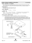
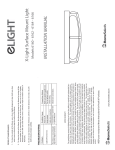
Warning! High power motor systems can be very dangerous! High currents can heat wires and batteries, causing fires and burning skin. Follow the wiring directions carefully! Model aircraft equipped with high power motors can kill. Always fly at a sanctioned field. Never fly over or near spectators. Even though this controller is equipped with a safety arming program, you should still use caution when connecting the i b GRIFFIN-55 By Castle Creations 55 Amp Micro Speed Control 1.0 • • • • • • • • • • • • • • 2.0 2.2 Features of the Griffin-55: Microprocessor controlled Extremely Low Resistance (.001 ohms) High rate (2800 Hz) switching (PWM) Up to 55 Amps continuous current (with proper air flow) Six to eight cells with three or four micro servos Up to ten cells with two micro servos. Sixteen cells MAX with BEC disabled. Dynamic braking ensures folding props fold promptly Dual Battery Eliminator Circuits (BECs) provide power to receiver and servos - eliminates separate receiver battery Auto Motor Cutoff with Reset Safe “power on” arming program ensures motor will not accidentally turn on Low torque “soft start” prevents damage to fragile gearboxes Auto shut down when signal is lost or radio interference becomes severe Rugged surface mount construction Attaching the Motor Leads The motor is connected to the right side of the controller (looking down at the heat sink/label). Cut the wires to the length you require on the motor side. Strip the wire insulation to expose just enough wire to solder the wires to the motor terminals. (Note: If you do not have a pair of wire strippers, you can use a modeling knife to carefully cut through the insulation around the wire. Then the insulation should easily pull off the wire). There should be a ‘+’ symbol or a RED DOT on the end of your motor which indicates which terminal must be connected to the RED wire. Connect the other terminal to the black wire. A fuse (50-60 amps or about 20% higher than expected continuous current) should be connected inline in either the black or red power wire. The manufacturer recommends that a fuse be used with this speed control. DO NOT PLACE A FUSE IN THE CIRCUIT BETWEEN THE BATTERY AND SPEED CONTROL. YOU COULD LOSE CONTROL OF THE MODEL. Align the wires carefully and solder to the motor terminals. Ensure that all connections (battery and motor) are correctly polarized. IMPORTANT NOTE: YOU MUST BE SURE THAT ALL CONNECTIONS ARE CORRECT WHEN CONNECTING THE SPEED CONTROLLER. Incorrectly connecting the speed control could cause permanent damage to the controller. Battery Wiring Your Griffin-55: Connector Griffin-55 Tools required: Fuse* Motor Griffin-55 ←Batt Motor→ Wire cutters Wire strippers (optional) Soldering Iron (25-40 watts - Do not use a soldering “gun”) Fig 1: System power wiring diagram Parts required: 2.3 Solder (rosin core “electronic” solder - do not use acid core “plumbers” solder) Battery connector Connect the receiver lead (the three color twisted wires with a connector on the end) to the throttle channel on your receiver (usually channel 3). Do not connect a battery to the receiver, as the Griffin-55 will supply power to the receiver and servos through the receiver connector. If you are using more than ten cells, you will need to use a separate receiver battery. The BEC on the Griffin-55 should not be used with motors that draw more than 35 amps. See the section 3.0 (under the heading BEC) for instructions on disabling the BEC to use a separate receiver battery. ALWAYS PERFORM A RANGE CHECK BEFORE FLYING WITH ANY NEW SPEED CONTROLLER! PERFORM YOUR RANGE CHECK AT FULL THROTTLE, HALF THROTTLE AND NO THROTTLE. 2.1 Adding the Battery Connector The battery connector is attached to the left side of the controller (looking down at the heat sink/label). Cut the wires to the length you require on the battery side. Strip off of the wire insulation to expose just enough wire to attach the battery connector. (Note: if you do not have a pair of wire strippers, you can use a modeling knife to carefully cut through the insulation around the wire. Then the insulation should easily pull off the wire.) Attach the battery connector to the wires ENSURING THAT THE POLARITY (red wire to battery red wire, black wire to battery black wire) IS CORRECT, following the instructions for the battery connector. Connecting the Receiver IMPORTANT NOTE: YOU MUST BE SURE THAT THE POLARITY IS CORRECT WHEN CONNECTING THE SPEED CONTROLLER. Incorrect polarity could permanently damage the controller. GRIFFIN-55 User Guide Page 1 of 2 * Suggested 50-60 Amp Rev 2-date 01/08/00 This document, Griffin-55 software, and Griffin-55 PCB layout are all Copyright 1999-2000 by Patrick del Castillo and Castle Creations Warning! High power motor systems can be very dangerous! High currents can heat wires and batteries, causing fires and burning skin. Follow the wiring directions carefully! Model aircraft equipped with high power motors can kill. Always fly at a sanctioned field. Never fly over or near spectators. Even though this controller is equipped with a safety arming program, you should still use caution when connecting the i b GRIFFIN-55 By Castle Creations 55 Amp Micro Speed Control 3.0 Flying with Your Griffin-55: Initialization sequence: 1. Connect the speed controller receiver connector to the proper channel on your receiver (usually channel 3) 2. Turn on your transmitter. 3. Connect the main power battery to the speed controller. 4. The speed controller will remain disarmed (will not operate) until it sees more than four seconds of “brake” throttle. Move the throttle arm to the lowest position on your transmitter, wait at least four seconds, and then test the controller to make sure that the throttle operates. 5. Go fly! 6. If the BEC cutoff occurs before you land, you may restart the motor and use low throttle if necessary by moving the throttle stick all the way down (to the brake position) and then throttling back up. BEC cutoff will occur again if the voltage drops too low. 4.0 Using the Features of Your Griffin-55 BEC - The BEC power is supplied to the receiver and servos through the receiver connector wires. If you wish to disable the BEC and use a separate receiver battery (required for the use of more than ten cells), you must first cut the red wire in the trio of receiver wires. Simply use a pair of wire cutters to remove a short section of the red wire near the receiver connector, and be sure to insulate the cut wire with a bit of electrical tape. Then you may safely use a battery with your receiver. Brake - moving the transmitter throttle stick to the bottom position enables the prop brake. Three seconds after the throttle has been in the brake position, braking will occur. If the brake does not come on in the lowest throttle position, adjust your transmitter trim down slightly. Cutoff - The motor cutoff will occur when the input battery voltage drops below 5.2V for more than one half second. Once motor cutoff has occurred, moving the throttle to the braking position (full off) can rearm the controller. This will allow restart of the motor at low throttle after cutoff has occurred. WARNING: Repeated restarting of the motor may drain the battery to the point where the radio receiver will stop operating, resulting in a loss of control of the model. Loss of Transmitter Signal, or excessive radio noise cutoff - Motor cutoff will also occur if the signal from the transmitter is lost, or if the radio noise becomes excessive. After radio connection has be reestablished, the motor can be restarted by moving the throttle to the braking position (full off) for four seconds. Safe Power Up - The Safe Power up feature is a “finger saver”, designed to prevent the motor from starting accidentally on power up. To arm the controller, the transmitter stick must be held in the “Brake” position (all the way down) for at least four seconds. Until the controller is armed, it will not provide any power to the motor, regardless of where the throttle stick on your transmitter is positioned. Before flying your model, be sure to “blip” the throttle to ensure that the controller is armed. 5.0 Everything is hooked up correctly, the BEC (receiver and servos) works, but the throttle does not work. The controller is not seeing the four seconds of “dead space” (low throttle) and is not arming. Try moving your throttle stick all the way down, and moving the trim all the way down. Wait for four seconds and try the throttle again. If it still does not arm, you may need to reverse the throttle control on your transmitter (see your radio documentation). You may also check to make sure that your endpoint adjustments on your radio (if it has them) are set all the way open. Every time I throttle all the way up, the controller “cuts off” after a few seconds, even with fresh charged batteries. The controller will automatically shut down the motor if the battery voltage falls below 5.2 volts for more than half a second. This is to protect your airplane from a loss of control caused by too low a voltage at the receiver. If the cutoff is kicking in with fresh charged batteries, it means that the voltage is dropping very quickly. This is usually an indication of a motor that is drawing too much current for the batteries to handle. Try using a smaller prop on the motor, or using batteries with a higher rating (for example, if you are using 800AR cells, you might try going to 1000SCR cells.) The brake doesn’t seem to work when I’m doing a static test. The brake has a three-second delay before activating. You will probably never see the brake operating on the ground, because the motor will be almost completely stopped by the time the brake activates. This delay is to prevent damage to gearboxes and belt drives. In the air, the motor will likely still be turning when the brake activates, and the brake action will be much more noticeable. Nothing seems to work, receiver and servos are dead, and the throttle is dead. Check all connections to ensure that they are correct, and that the polarity (+/-) connections are correct. Ensure that the battery is not connected to the motor side of the speed controller. If everything is correctly connected, and the receiver and servos still do not work, contact the dealer where you purchased your Griffin-55 or Contact Castle Creations directly. (See info below) CONTACT/WARRANTY INFORMATION Your Griffin-55 is warranted for 90 days from date of purchase to be free from manufacturing and component defects. This warranty does not cover abuse, neglect, or damage due to incorrect wiring, over voltage, or overloading. If you have any questions, comments, or wish to return your Griffin-55 for warranty or after warranty repair/replacement contact Castle Creations at: Patrick del Castillo Castle Creations 18773 W 117th St. Olathe KS, 66061 Email: [email protected] (913) 438-6325 http://www.castlerc.com Troubleshooting GRIFFIN-55 User Guide Page 2 of 2 Rev 2-date 01/08/00 This document, Griffin-55 software, and Griffin-55 PCB layout are all Copyright 1999-2000 by Patrick del Castillo and Castle Creations