1
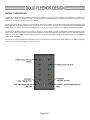
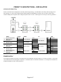
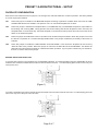
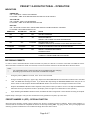
PRESET 10 ARCHITECTURAL
OWNERS MANUAL
Doug Fleenor Design
396 Corbett Canyon Road
Arroyo Grande, CA 93420
(805) 481-9599
Software Version 2.0
Manual Revision 5
February , 2006
$ Serial # 05C183
PRODUCT DESCRIPTION
The Preset 10 Architectural is a lighting control station capable of storing up to ten presets. These presets are recorded by
capturing the output of a DMX512 console. Each preset can then be assigned a unique fade tim e, from 0 to 999 seconds.
Presets are recalled by pressing one of the buttons.
System s can be created by using one or m ore stations and a power supply. The solid alum inum faceplate is designed to install
over a standard single gang electrical box. Connections to the Preset 10 Architectural are power (2 wires) and DMX512 (3
wires). Power for the Preset 10 can be supplied from a variety of sources, including a 10V class 2 “doorbell” transform er.
The Preset 10 Architectural system can work in conjunction with a lighting console, autom atically switching between preset
and console control. W hen the console generates DMX the Preset 10 Architectural goes off-line. The console then operates
norm ally. Upon loss of DMX from the console, the Preset 10 Architectural either returns to its pervious preset or holds the last
look (jum per selectable).
The Preset 10 system also com es in a portable version (m odel PRE10-P) that acts as a backup station for any DMX512 lighting
console or as a stand-alone DMX512 preset console.
Page 2 of 7
SPECIFICATIONS
Connector:
Phoenix Contact MSTB series 5 position two part term inal block
Model: MSTB 2,5/5-ST-5,08 Order Num ber: 17 57 04 8
Connector pin out:
1
2
3
4
5
Input/Output Circuit:
ESD protected EIA-485 transceiver (LT1785)
Indicators:
Ten green preset indicator LEDs
One yellow Fade Tim e LED
One red Signal / Record LED
User controls:
Ten preset push buttons
One recessed record push button
One recessed fade tim e push button
Option Jum pers:
For a single station installation all jum pers should be installed. (see figure 1, page 5)
(C)
( -)
(+)
(C)
(V)
DMX512 com m on
DMX512 data DMX512 data +
Supply com m on (internally tied to pin1)
Supply voltage “hot”
INSTALLED
REM OVED
JP1
Recording Enabled
Recording Disabled
JP2
Master Station
Slave Station
JP3
Architectural Mode
Portable Mode
JP4
Single Station Mode
Multi Station Mode
Power input:
9 to 24 volts DC or 10 to 16 volts AC / 200m A per station
(A 10 volt class 2 “doorbell” transform er is recom m ended for fixed installations)
Color:
Black anodized with silver engraved nom enclature
Size :
Faceplate: 4.5"h X 2.75"w X 0.2"d
Faceplate rear inset: 4.05"h X 2.4"w X 0.1"d
Electrical box m inim um inside dim ensions: 3.5"h X 2.1"w X 1.25"d
Page 3 of 7
PRESET 10 ARCHITECTURAL - INSTALLATION
WIRING INFORMATION
Preset 10 Architectural is designed to use daisy-chain wiring topology. An alternative to the daisy-chain topology is the
star topology. To create a star a bidirectional isolated splitter (m odel BiDi8) is required. Also note that a system m ay
contain m ultiple power supplies when voltage drop becom es a concern. Please give us a call if you have any questions.
1
2
3
4
5
CABLE
120 Ohm Data Cable
Belden 9829 or
Equivalent
(2) #16 AWG
Stranded Wires
120 Ohm Data Cable
Belden 9829 or
Equivalent
(2) #16 AWG
Stranded Wires
120 Ohm Data Cable
Belden 9829 or
Equivalent
COLOR
Shield
White/Blue
Blue/White
Black
Red
Shield
White/Blue
Blue/White
Black
Red
Shield
White/Blue
Blue/White
FROM
TO
5 Pin XLR Plate
Power Supply
PRE10 Master
PRE10 Slave
Pin 1
Pin 2
Pin 3
Common
Power
TB1-1
TB1-2
TB1-3
TB1-4
TB1-5
TB1-1
TB1-2
TB1-3
PRE10 Master
PRE10 Slave
Dimmer Cabinet
TB1TB1TB1TB1TB1TB1TB1TB1TB1TB1?
?
?
USE
Common
Data Data +
Supply
Supply “hot”
Common
Data Data +
Supply
Supply “hot”
Common
Data Data +
POWER SUPPLY
The voltage provided to the Preset 10 Architectural m ust be between 9 and 24 volts DC or 10 and 16 volts AC. The Preset
10 Architectural has been designed to operate on a standard class 2 “doorbell” transform er. For exam ple Ace Hardware’s
m odel# ACE36483 10 volt 5 watt transform er.
Page 4 of 7
PRESET 10 ARCHITECTURAL - SETUP
FACEPLATE CONFIGURATION
Each Preset 10 Architectural has four jum pers, JP1 through JP4, that select different m odes of operation. The factory default
is to have all jum pers installed.
JP1
W hen this jum per is installed on the MASTER faceplate recording of presets is enabled. W hen rem oved, the TIME
and RECORD buttons are disabled. The position of JP1 on a SLAVE faceplate has no affect.
JP2
W hen this jum per is installed the faceplate takes on the MASTER duty. The MASTER faceplate is responsible for
transm itting and receiving DMX, storing presets and com m unicating with SLAVE faceplates. W hen rem oved, the
faceplate takes on the SLAVE duty. A SLAVE faceplate com m unicates button presses and m im ics the state of the
LEDs on the m aster faceplate.
JP3
W hen the jum per is installed the Preset 10 operates as an architectural preset station. W hen this jum per is rem oved
the Preset 10 operates as a console backup/portable station. This jum per m odifies the personality of the Preset 10
software.
JP4
W hen this jum per is installed it enables SINGLE STATION MODE. In this m ode the faceplate will not send any
"alternate start code" packets. W hen this jum per is rem oved it enables MULTI STATION MODE. This allows the
alternate start code packets required for m aster/slave station operation. If your system contains only one Preset 10,
there is no need to rem ove the jum per.
M ASTER AND SLAVE SELECTION
In a system with m ore than one faceplate only one MASTER is allowed. To modify faceplate to becom e a MASTER, the shunt
located at JP2 should be installed and the shunt at JP4 should be rem oved. For safe keeping place the shunt over only one
of the pins at JP4.
(Figure 1)
To m odify a faceplate to becom e a SLAVE the shunts located at JP2 and JP4 should be rem oved. For safe keeping place the
shunt over only one of the pins at JP2 and JP4.
(Figure 2)
Page 5 of 7
PRESET 10 ARCHITECTURAL - OPERATION
INDICATORS
GREEN LED
ON = CURRENTLY SELECTED PRESET
FLASHING = TIME SETTING MODE SELECTED FOR THIS PRESET
YELLOW LED
ON = PRESET FADE IS IN PROGRESS
FLASHING = TIME SETTING MODE SELECTED
RED LED
ON = STATION LOCKED OUT / RECEIVING DMX512 FROM EXTERNAL CONSOLE
FLASHING = RECORD MODE ACTIVE
GREEN LED
YELLOW LED
RED LED
STATE
OFF
OFF
OFF
UNIT NOT POWERED
OFF
OFF
ON
RECEIVING DMX512
PRESET 10 IS LOCKED OUT FROM TRANSMITTING
OFF
OFF
FLASHING
FLASHING
FLASHING
OFF
TIME SETTING MODE ACTIVE FOR SELECTED PRESET
ON
OFF
OFF
PRESET 10 TRANSMITTING DMX512
NO DMX512 INPUT
ON
ON
OFF
PRESET 10 TRANSMITTING DMX512
CURRENTLY FADING FROM PREVIOUS PRESET
RECORD MODE ACTIVE
CURRENT LOOK WILL BE STORED TO THE NEXT PRESSED PRESET
RECORDING PRESETS
In order to set the individual dim m er levels recorded to a preset, the Preset 10 m ust be connected to a DMX512 source.
W hen less than 512 dim m er levels are received, a level of 0% will be stored for all channels above those received.
Note:
!
!
1.
2.
For predictable results, avoid recording when the DMX levels are changing.
Recording of presets m ust be done from the MASTER faceplate
Using the prim ary DMX512 console, set a “look” to be recorded.
Using a sm all blunt object (i.e. paper clip), depress the RECORD MODE recessed button located next to the RED
LED. The RED LED will begin to flash. If you decide after depressing the RECORD MODE button that you do not
wish to m ake an edit, depress the RECORD MODE button a second tim e. No changes will have been m ade.
3.
Depress the PRESET SELECT button adjacent to the preset num ber you wish to record. The adjacent GREEN LED
will illum inate as you depress the button. (Exam ple: press the upper m ost left button to store preset 1)
4.
Upon releasing the PRESET SELECT button, the RED LED will no longer flash. This Indicates recording is com plete.
Repeat steps 1 through 4 until you have recorded as m any presets as required, up to ten total.
PRESET NUMBER 10 (OFF) - SPECIAL FUNCTION
W hen the levels stored in preset num ber 10(OFF) are all zeros a special function is enabled. W hen preset 10(OFF) is
selected and the crossfade is com pleted the Preset 10 will stop sending DMX. By going off-line, m any m oving lights and
dim m ing system s will detect the loss of DMX and begin their shut down routine.
Page 6 of 7
RECORDING PRESET CROSSFADE TIME
A crossfade is a fade where the new preset levels entirely replace the previous levels. Each of the ten presets can have
its own unique crossfade tim e. Crossfade tim es default to five seconds.
Note:
!
Crossfade tim es range from a m inim um of 0 second to as m axim um of 999 seconds(16 Min., 39 Sec.).
!
Crossfade tim es can not be set while the Preset 10 is locked out (red LED is illum inated).
To enter a different crossfade tim e:
1.
Disconnect the Preset Ten from any DMX512 source.
2.
Press the button of the preset you wish to edit. The GREEN preset indicator LED will illum inate.
3.
Using a sm all blunt object (i.e. paper clip), depress the TIME SETTING MODE recessed button located adjacent
to the yellow LED indicator. The green indicator LED, adjacent to the preset you selected to edit and yellow tim e
will now flash. You will have ten seconds to set the crossfade tim e. If you decide after depressing the TIME
SETTING MODE button that you do not wish to m ake an edit sim ply wait 10 seconds, or depress the TIME
SETTING MODE button a second tim e. No changes will have been m ade.
4.
Enter the tim e in seconds using the PRESET SELECT buttons. Use PRESET SELECT button 10(OFF) to enter
a zero. (i.e. 120 seconds is entered by pressing PRESET SELECT button 1 followed by 2 then OFF). The tim e
setting com m and is com pleted by one of three m ethods:
a.
Enter a three-digit tim e. The TIME SETTING MODE will exit upon the entry of the third digit. The GREEN
preset indicator LED will illum inate steadily and the yellow LED will go off indicating success. A one or two
digit tim e m ay be entered with leading zeros (i.e. five seconds as 005 or OFF, OFF, 5).
b.
Enter a one or two digit tim e followed by pressing the TIME SETTING MODE button. The GREEN preset
indicator LED will illum inate steadily and the yellow LED will go off indicating success.
c.
Enter a one or two digit tim e and wait for ten seconds for the tim e setting m ode to exit autom atically. The
GREEN preset indicator LED will illum inate steadily and the yellow LED will go off indicating success.
PLAYBACK OF PRESETS
Presets can be played back in one of two ways, a crossfade to a static preset or an autofollow of all ten presets. A crossfade
is a change from the current preset to the newly selected one. The tim e taken to fade from the current preset to the new
preset is taken from the newly selected preset. Once the fade has com pleted it will rem ain at that current preset (static) until
another preset is selected. W hen the autofollow m ethod of playback is used once the fade tim e of the currently fading preset
is com pleted the next preset is autom atically selected.
To begin a crossfade between presets m om entarily press the preset select button of the preset you wish to play.
To begin autofollow of all ten presets press and hold the preset select button of preset num ber 1 (approxim ately 5 seconds)
until all the LEDs flash once. Once the fade tim e of a preset is com plete the next preset will be selected autom atically. W hen
preset num ber 10(OFF) has been reached the next preset to be selected will be preset num ber 1.
To exit autofollow m om entarily press any preset select button.
Note:
!
If a static preset is playing at the tim e power is lost Preset 10 will return to that preset when power is restored. The
fade will begin with all 512 channels at 0% and fade up in the tim e recorded to that preset.
!
If the Preset 10 was in autofollow playback at the tim e power was lost, the Preset 10 will resum e autofollow playback
beginning with preset num ber 1.
!
To bypass unused presets In autofollow enter the tim e as 999 seconds. This m eans the longest autofollow fade
tim e is 998 seconds.
PRESET NUMBER 10 (OFF) - SPECIAL FUNCTION
W hen the levels stored in preset num ber 10(OFF) are all zeros a special function is enabled. W hen preset 10(OFF) is
selected and the crossfade has com pleted the Preset 10 will stop sending DMX. By ending DMX transm ission, m any m oving
lights and dim m ing system s will enter their standby m ode.
Page 7 of 7