1
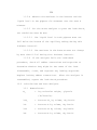
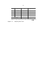
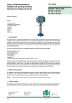
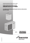
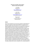
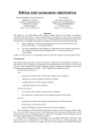
312
METHOD 3 - GAS ANALYSIS FOR THE
DETERMINATION OF DRY MOLECULAR WEIGHT
NOTE:
This method does not include all of the
specifications (e.g., equipment and supplies) and procedures
(e.g., sampling) essential to its performance.
Some
material is incorporated by reference from other methods in
this part.
Therefore, to obtain reliable results, persons
using this method should also have a thorough knowledge of
Method 1.
1.0
Scope and Application.
1.1
Analytes.
Analyte
CAS No.
Sensitivity
Oxygen (O2)
7782-44-7
2,000 ppmv
Nitrogen (N2)
7727-37-9
N/A
Carbon dioxide (CO2)
124-38-9
2,000 ppmv
Carbon monoxide (CO)
630-08-0
N/A
1.2
Applicability.
This method is applicable for the
determination of CO2 and O2 concentrations and dry molecular
weight of a sample from an effluent gas stream of a fossilfuel combustion process or other process.
1.3
Other methods, as well as modifications to the
procedure described herein, are also applicable for all of
the above determinations.
modifications include:
Examples of specific methods and
(1) a multi-point grab sampling
method using an Orsat analyzer to analyze the individual
313
grab sample obtained at each point; (2) a method for
measuring either CO2 or O2 and using stoichiometric
calculations to determine dry molecular weight; and (3)
assigning a value of 30.0 for dry molecular weight, in lieu
of actual measurements, for processes burning natural gas,
coal, or oil.
These methods and modifications may be used,
but are subject to the approval of the Administrator.
The
method may also be applicable to other processes where it
has been determined that compounds other than CO2, O2,
carbon monoxide (CO), and nitrogen (N2) are not present in
concentrations sufficient to affect the results.
1.4
Data Quality Objectives.
Adherence to the
requirements of this method will enhance the quality of the
data obtained from air pollutant sampling methods.
2.0
Summary of Method.
2.1
A gas sample is extracted from a stack by one of
the following methods:
(1) single-point, grab sampling; (2)
single-point, integrated sampling; or (3) multi-point,
integrated sampling.
CO2 and percent O2.
The gas sample is analyzed for percent
For dry molecular weight determination,
either an Orsat or a Fyrite analyzer may be used for the
analysis.
3.0
Definitions.
4.0
Interferences.
[Reserved]
314
4.1
Several compounds can interfere, to varying
degrees, with the results of Orsat or Fyrite analyses.
Compounds that interfere with CO2 concentration measurement
include acid gases (e.g., sulfur dioxide, hydrogen
chloride); compounds that interfere with O2 concentration
measurement include unsaturated hydrocarbons (e.g., acetone,
acetylene), nitrous oxide, and ammonia.
Ammonia reacts
chemically with the O2 absorbing solution, and when present
in the effluent gas stream must be removed before analysis.
5.0
Safety.
5.1
Disclaimer.
This method may involve hazardous
materials, operations, and equipment.
This test method may
not address all of the safety problems associated with its
use.
It is the responsibility of the user of this test
method to establish appropriate safety and health practices
and determine the applicability of regulatory limitations
prior to performing this test method.
5.2
5.2.1
Corrosive Reagents.
reagents:
A typical Orsat analyzer requires four
a gas-confining solution, CO2 absorbent, O2
absorbent, and CO absorbent.
These reagents may contain
potassium hydroxide, sodium hydroxide, cuprous chloride,
cuprous sulfate, alkaline pyrogallic acid, and/or chromous
315
chloride.
Follow manufacturer's operating instructions and
observe all warning labels for reagent use.
5.2.2
A typical Fyrite analyzer contains zinc
chloride, hydrochloric acid, and either potassium hydroxide
or chromous chloride.
Follow manufacturer's operating
instructions and observe all warning labels for reagent use.
6.0
Equipment and Supplies.
NOTE:
As an alternative to the sampling apparatus and
systems described herein, other sampling systems (e.g.,
liquid displacement) may be used, provided such systems are
capable of obtaining a representative sample and maintaining
a constant sampling rate, and are, otherwise, capable of
yielding acceptable results.
Use of such systems is subject
to the approval of the Administrator.
6.1
6.1.1
Grab Sampling (See Figure 3-1).
Probe.
Stainless steel or borosilicate glass
tubing equipped with an in-stack or out-of-stack filter to
remove particulate matter (a plug of glass wool is
satisfactory for this purpose).
Any other materials,
resistant to temperature at sampling conditions and inert to
all components of the gas stream, may be used for the probe.
Examples of such materials may include aluminum, copper,
quartz glass, and Teflon.
316
6.1.2
Pump.
A one-way squeeze bulb, or equivalent,
to transport the gas sample to the analyzer.
6.2
Integrated Sampling (Figure 3-2).
6.2.1
Probe.
Same as in Section 6.1.1.
6.2.2
Condenser.
An air-cooled or water-cooled
condenser, or other condenser no greater than 250 ml that
will not remove O2, CO2, CO, and N2, to remove excess
moisture which would interfere with the operation of the
pump and flowmeter.
6.2.3
Valve.
A needle valve, to adjust sample gas
flow rate.
6.2.4
Pump.
A leak-free, diaphragm-type pump, or
equivalent, to transport sample gas to the flexible bag.
Install a small surge tank between the pump and rate meter
to eliminate the pulsation effect of the diaphragm pump on
the rate meter.
6.2.5
Rate Meter.
A rotameter, or equivalent,
capable of measuring flow rate to ± 2 percent of the
selected flow rate.
A flow rate range of 500 to 1000 ml/min
is suggested.
6.2.6
Flexible Bag.
Any leak-free plastic (e.g.,
Tedlar, Mylar, Teflon) or plastic-coated aluminum (e.g.,
aluminized Mylar) bag, or equivalent, having a capacity
consistent with the selected flow rate and duration of the
317
test run.
A capacity in the range of 55 to 90 liters (1.9
to 3.2 ft3) is suggested.
To leak-check the bag, connect it
to a water manometer, and pressurize the bag to 5 to 10 cm
H2O (2 to 4 in. H2O).
Allow to stand for 10 minutes.
Any
displacement in the water manometer indicates a leak.
An
alternative leak-check method is to pressurize the bag to 5
to 10 cm (2 to 4 in.) H2O and allow to stand overnight.
A
deflated bag indicates a leak.
6.2.7
Pressure Gauge.
A water-filled U-tube
manometer, or equivalent, of about 30 cm (12 in.), for the
flexible bag leak-check.
6.2.8
Vacuum Gauge.
A mercury manometer, or
equivalent, of at least 760 mm (30 in.) Hg, for the sampling
train leak-check.
6.3
Analysis.
An Orsat or Fyrite type combustion gas
analyzer.
7.0
Reagents and Standards.
7.1
Reagents.
As specified by the Orsat or Fyrite-
type combustion analyzer manufacturer.
7.2
Standards.
Two standard gas mixtures, traceable
to National Institute of Standards and Technology (NIST)
standards, to be used in auditing the accuracy of the
analyzer and the analyzer operator technique:
318
7.2.1.
Gas cylinder containing 2 to 4 percent O2 and
14 to 18 percent CO2.
7.2.2.
Gas cylinder containing 2 to 4 percent CO2 and
about 15 percent O2.
8.0
Sample Collection, Preservation, Storage, and
Transport.
8.1
8.1.1
Single Point, Grab Sampling Procedure.
The sampling point in the duct shall either be
at the centroid of the cross section or at a point no closer
to the walls than 1.0 m (3.3 ft), unless otherwise specified
by the Administrator.
8.1.2
Set up the equipment as shown in Figure 3-1,
making sure all connections ahead of the analyzer are tight.
If an Orsat analyzer is used, it is recommended that the
analyzer be leak-checked by following the procedure in
Section 11.5; however, the leak-check is optional.
8.1.3
Place the probe in the stack, with the tip of
the probe positioned at the sampling point.
Purge the
sampling line long enough to allow at least five exchanges.
Draw a sample into the analyzer, and immediately analyze it
for percent CO2 and percent O2 according to Section 11.2.
8.2
8.2.1
Single-Point, Integrated Sampling Procedure.
The sampling point in the duct shall be located
as specified in Section 8.1.1.
319
8.2.2
Leak-check (optional) the flexible bag as in
Section 6.2.6.
Figure 3-2.
Set up the equipment as shown in
Just before sampling, leak-check (optional) the
train by placing a vacuum gauge at the condenser inlet,
pulling a vacuum of at least 250 mm Hg (10 in. Hg), plugging
the outlet at the quick disconnect, and then turning off the
pump.
The vacuum should remain stable for at least
0.5 minute.
Evacuate the flexible bag.
Connect the probe,
and place it in the stack, with the tip of the probe
positioned at the sampling point.
Purge the sampling line.
Next, connect the bag, and make sure that all connections
are tight.
8.2.3
Sample Collection.
(± 10 percent).
Sample at a constant rate
The sampling run should be simultaneous
with, and for the same total length of time as, the
pollutant emission rate determination.
Collection of at
least 28 liters (1.0 ft3) of sample gas is recommended;
however, smaller volumes may be collected, if desired.
8.2.4
Obtain one integrated flue gas sample during
each pollutant emission rate determination.
Within 8 hours
after the sample is taken, analyze it for percent CO2 and
percent O2 using either an Orsat analyzer or a Fyrite type
combustion gas analyzer according to Section 11.3.
320
NOTE:
When using an Orsat analyzer, periodic Fyrite
readings may be taken to verify/confirm the results obtained
from the Orsat.
8.3
Multi-Point, Integrated Sampling Procedure.
8.3.1
Unless otherwise specified in an applicable
regulation, or by the Administrator, a minimum of eight
traverse points shall be used for circular stacks having
diameters less than 0.61 m (24 in.), a minimum of nine shall
be used for rectangular stacks having equivalent diameters
less than 0.61 m (24 in.), and a minimum of 12 traverse
points shall be used for all other cases.
The traverse
points shall be located according to Method 1.
8.3.2
Follow the procedures outlined in Sections
8.2.2 through 8.2.4, except for the following:
Traverse all
sampling points, and sample at each point for an equal
length of time.
Figure 3-3.
Record sampling data as shown in
321
9.0
Quality Control.
Section
Quality Control
Measure
Effect
8.2
Use of Fyrite to
confirm Orsat results.
Ensures the accurate
measurement of CO2 and
O2.
10.1
Periodic audit of
analyzer and operator
technique.
Ensures that the
analyzer is operating
properly and that the
operator performs the
sampling procedure
correctly and
accurately.
11.3
Replicable analyses of
integrated samples.
Minimizes experimental
error.
10.0
Calibration and Standardization.
10.1
Analyzer.
The analyzer and analyzer operator's
technique should be audited periodically as follows:
take a
sample from a manifold containing a known mixture of CO2 and
O2, and analyze according to the procedure in Section 11.3.
Repeat this procedure until the measured concentration of
three consecutive samples agrees with the stated value ± 0.5
percent.
If necessary, take corrective action, as specified
in the analyzer users manual.
10.2
Rotameter.
The rotameter need not be
calibrated, but should be cleaned and maintained according
to the manufacturer's instruction.
11.0
Analytical Procedure.
322
11.1
Maintenance.
The Orsat or Fyrite-type analyzer
should be maintained and operated according to the
manufacturers specifications.
11.2
Grab Sample Analysis.
Use either an Orsat
analyzer or a Fyrite-type combustion gas analyzer to measure
O2 and CO2 concentration for dry molecular weight
determination, using procedures as specified in the analyzer
user's manual.
If an Orsat analyzer is used, it is
recommended that the Orsat leak-check, described in Section
11.5, be performed before this determination; however, the
check is optional.
Calculate the dry molecular weight as
indicated in Section 12.0.
Repeat the sampling, analysis,
and calculation procedures until the dry molecular weights
of any three grab samples differ from their mean by no more
than 0.3 g/g-mole (0.3 lb/lb-mole).
Average these three
molecular weights, and report the results to the nearest 0.1
g/g-mole (0.1 lb/lb-mole).
11.3
Integrated Sample Analysis.
Use either an Orsat
analyzer or a Fyrite-type combustion gas analyzer to measure
O2 and CO2 concentration for dry molecular weight
determination, using procedures as specified in the analyzer
user's manual.
If an Orsat analyzer is used, it is
recommended that the Orsat leak-check, described in
Section 11.5, be performed before this determination;
323
however, the check is optional.
Calculate the dry molecular
weight as indicated in Section 12.0.
Repeat the analysis
and calculation procedures until the individual dry
molecular weights for any three analyses differ from their
mean by no more than 0.3 g/g-mole (0.3 lb/lb-mole).
Average
these three molecular weights, and report the results to the
nearest 0.1 g/g-mole (0.1 lb/lb-mole).
11.4
Standardization.
A periodic check of the
reagents and of operator technique should be conducted at
least once every three series of test runs as outlined in
Section 10.1.
11.5
Leak-Check Procedure for Orsat Analyzer.
an Orsat analyzer frequently causes it to leak.
Moving
Therefore,
an Orsat analyzer should be thoroughly leak-checked on site
before the flue gas sample is introduced into it.
The
procedure for leak-checking an Orsat analyzer is as follows:
11.5.1
Bring the liquid level in each pipette up to
the reference mark on the capillary tubing, and then close
the pipette stopcock.
11.5.2
Raise the leveling bulb sufficiently to bring
the confining liquid meniscus onto the graduated portion of
the burette, and then close the manifold stopcock.
11.5.3
Record the meniscus position.
324
11.5.4
Observe the meniscus in the burette and the
liquid level in the pipette for movement over the next 4
minutes.
11.5.5
For the Orsat analyzer to pass the leak-check,
two conditions must be met:
11.5.5.1
The liquid level in each pipette must not
fall below the bottom of the capillary tubing during this
4-minute interval.
11.5.5.2
The meniscus in the burette must not change
by more than 0.2 ml during this 4-minute interval.
11.5.6
If the analyzer fails the leak-check
procedure, check all rubber connections and stopcocks to
determine whether they might be the cause of the leak.
Disassemble, clean, and regrease any leaking stopcocks.
Replace leaking rubber connections.
After the analyzer is
reassembled, repeat the leak-check procedure.
12.0
Calculations and Data Analysis.
12.1
Md
Nomenclature.
=
Dry molecular weight, g/g-mole
(lb/lb-mole).
%CO2
=
Percent CO2 by volume, dry basis.
%O2
=
Percent O2 by volume, dry basis.
%CO
=
Percent CO by volume, dry basis.
%N2
=
Percent N2 by volume, dry basis.
325
0.280
=
Molecular weight of N2 or CO, divided by
100.
0.320
=
Molecular weight of O2 divided by 100.
0.440
=
Molecular weight of CO2 divided by 100.
12.2
Nitrogen, Carbon Monoxide Concentration.
Determine the percentage of the gas that is N2 and CO by
subtracting the sum of the percent CO2 and percent O2 from
100 percent.
12.3
Dry Molecular Weight.
Use Equation 3-1 to
calculate the dry molecular weight of the stack gas.
M d ' 0.440(%CO2) % 0.320 (%O2) % 0.280 (%N2 % %CO)
NOTE:
Eq. 3-1
The above Equation 3-1 does not consider the
effect on calculated dry molecular weight of argon in the
effluent gas.
The concentration of argon, with a molecular
weight of 39.9, in ambient air is about 0.9 percent.
A
negative error of approximately 0.4 percent is introduced.
The tester may choose to include argon in the analysis using
procedures subject to approval of the Administrator.
13.0
Method Performance.
[Reserved]
14.0
Pollution Prevention.
15.0
Waste Management.
16.0
References.
[Reserved]
[Reserved]
326
1.
Altshuller, A.P.
Plastic Bags.
Pollution.
2.
International Journal of Air and Water
6:75-81.
1963.
Conner, William D. and J.S. Nader.
with Plastic Bags.
Air Sampling
Journal of the American Industrial
Hygiene Association.
3.
Storage of Gases and Vapors in
25:291-297.
1964.
Burrell Manual for Gas Analysts, Seventh edition.
Burrell Corporation, 2223 Fifth Avenue, Pittsburgh, PA.
15219.
1951.
4.
Mitchell, W.J. and M.R. Midgett.
Reliability of the Orsat Analyzer.
Control Association.
5.
26:491-495.
Field
Journal of Air Pollution
May 1976.
Shigehara, R.T., R.M. Neulicht, and W.S. Smith.
Validating Orsat Analysis Data from Fossil Fuel-Fired Units.
Stack Sampling News.
17.0
4(2):21-26.
August 1976.
Tables, Diagrams, Flowcharts, and Validation Data.
327
Filter
(Glass Wool)
Flexible Tubing
Probe
Squeeze Bulb
Figure 3-1.
Grab-Sampling Train.
To Analyzer
328
Rate Meter
Filter
(Glass Wool)
Valve
Surge
Tank
Probe
Quick
Disconnect
Air-Tight
Pump
Air-Cooled
Condenser
Bag
Valve
Figure 3-2.
Rigid Container
Integrated Gas-Sampling Train.
329
Time
Traverse
Point
Q
(liter/min)
% Deviationa
Average
a
%Dev. = [(Q - Qavg)/Qavg] x 100
Figure 3-3.
Sampling Rate Data.
(Must be < + 10 %)