1
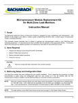
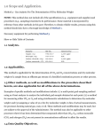
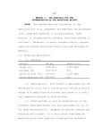
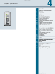
FYRITE® Gas Analyzer CO2 and O2 Indicators Operation and Maintenance Manual Registered Trademark S/N: 73485726 Reg #: 1335241 Printed in U.S.A. P/N: 0011-9026 Revision 13 October 2015 Product Leadership • Training • Service • Reliability ® FYRITE Gas Analyzer Warranty Bacharach, Inc. warrants to Buyer that at the time of delivery this Product will be free from defects in material and manufacture and will conform substantially to Bacharach Inc.’s applicable specifications. Bacharach’s liability and Buyer’s remedy under this warranty are limited to the repair or replacement, at Bacharach’s option, of this Product or parts thereof returned to Seller at the factory of manufacture and shown to Bacharach Inc.’s reasonable satisfaction to have been defective; provided that written notice of the defect shall have been given by Buyer to Bacharach Inc. within one (1) year after the date of delivery of this Product by Bacharach, Inc. Bacharach, Inc. warrants to Buyer that it will convey good title to this Product. Bacharach’s liability and Buyer’s remedy under this warranty of title are limited to the removal of any title defects or, at the election of Bacharach, to the replacement of this Product or parts thereof that are defective in title. The warranty set forth in paragraph 1 does not apply to parts the operating instructions designate as having a limited shelf-life or as being expended in normal use. THE FOREGOING WARRANTIES ARE EXCLUSIVE AND ARE GIVEN AND ACCEPTED IN LIEU OF (I) ANY AND ALL OTHER WARRANTIES, EXPRESS OR IMPLIED, INCLUDING WITHOUT LIMITATION THE IMPLIED WARANTIES OF MERCHANTABILITY AND FITNESS FOR A PARTICULAR PURPOSE: AND (II) ANY OBLIGATION, LIABILITY, RIGHT, CLAIM OR REMEDY IN CONTACT OR TORT, WHETHER OR NOT ARISING FROM BACHARACH’S NEGLIGENCE, ACTUAL OR IMPLIED. The remedies of the Buyer shall be limited to those provided herein to the exclusion of any and all other remedies including, without limitation incidental or consequential damages. No agreement varying or extending the foregoing warranties, remedies or this limitation will be binding upon Bacharach, Inc. unless in writing, signed by a duly authorized officer of Bacharach. NOTE: Gaskets are considered consumable items and are excluded from the terms of this warranty. Register your warranty by visiting www.MyBacharach.com CAUTION: Corrosive fluid is contained inside FYRITE®. instructions thoroughly before any operation or testing begins. Read all Copyright © 1998-2015 Bacharach, Inc. All rights reserved. 2 0011-9026 Rev 13 ® FYRITE Gas Analyzer Table of Contents Section 1. Introduction .............................................................................................. 5 1.1. Safety .................................................................................................................... 5 1.2. Fluid Handling Precautions ................................................................................... 6 1.3. Product Overview ................................................................................................. 6 1.4. Specifications ........................................................................................................ 8 Section 2. Before You Test ........................................................................................10 2.1. Inspect the FYRITE® Aspirator Bulb and Sampling Assembly .............................. 10 2.2. Check Fluid Strength ........................................................................................... 11 2.2.1. CO2 FYRITE® Fluid Only ........................................................................... 12 2.2.2. O2 FYRITE® Fluid Only ............................................................................. 13 2.3. Sampling Assembly ............................................................................................. 13 2.4. Moisten the Filter as Appropriate ...................................................................... 14 Section 3. Basic Operation (%CO2 and %O2) ..............................................................16 3.1. Overview ............................................................................................................ 16 3.2. Determining CO2 and O2 FYRITE® Fluid Strength ................................................ 20 3.3. Operating Precautions to Ensure Maximum Accuracy ....................................... 20 3.4. FYRITE® Temperature and Gas Sample Temperature......................................... 21 Section 4. Principle of Operation ..............................................................................22 Section 5. Application Information ...........................................................................24 5.1. FYRITE® Absorbing Fluid ..................................................................................... 24 5.2. CO2 FYRITE® Only Combustion Testing ............................................................... 25 5.2.1. Percent CO2 Shows Volume of Excess Air .............................................. 25 5.2.2. Too Much Excess Air Means Inefficient Combustion ............................. 26 5.2.3. Proper CO2 Value ................................................................................... 26 5.2.4. How to Calculate Combustion Efficiency ............................................... 27 5.3. O2 FYRITE® Only Combustion Testing ................................................................. 28 5.3.1. Percent O2 Shows Volume of Excess Combustion Air ............................ 28 5.3.2. Too Much Excess Air Means Inefficient Combustion ............................. 28 5.3.3. Proper O2 Value...................................................................................... 28 5.3.4. Measuring O2 in Addition to CO2 ............................................................ 28 5.3.5. Where is Percent CO2 or O2 Measured? ................................................. 28 5.4. Background Gases Affecting FYRITE® Readings .................................................. 29 5.5. General FYRITE® Applications ............................................................................. 30 5.6. Altitude Correction Table ................................................................................... 31 ® Section 6. FYRITE Maintenance ...............................................................................32 6.1. Increasing and Decreasing FYRITE® Fluid to Proper Level .................................. 32 6.2. Replacing FYRITE® Fluid ...................................................................................... 33 6.3. Inspection of FYRITE® for Fluid Leakage ............................................................. 34 6.4. Cleaning FYRITE® ................................................................................................ 35 6.5. Replacing FYRITE® Parts...................................................................................... 35 6.6. Storing FYRITE® and Refill Fluid .......................................................................... 37 0011-9026 Rev 13 3 ® FYRITE Gas Analyzer 6.7. Replacing the Saturator Filter Package ............................................................... 38 Section 7. Illustrated Parts List..................................................................................39 7.1. FYRITE® Parts ...................................................................................................... 39 7.2. FYRITE® Sampling Assembly Parts ...................................................................... 41 7.3. Service and Support............................................................................................ 42 4 0011-9026 Rev 13 ® FYRITE Gas Analyzer Section 1. Introduction 1.1. Safety The operator(s) of this instrument should thoroughly familiarize themselves with the applicable safety precautions before handling or using the FYRITE® for gas analysis. Review the illustrations on this page. Make certain to follow the steps outlined below and read the fluid handling precautions for your personal safety. 1) 2) 3) 4) Always use protective equipment such as safety goggles, gloves, and protective clothing as illustrated in Figure 1. Read the instruction manual thoroughly. When filling the FYRITE® with the applicable fluid charge, use safety equipment and perform the operation in the vicinity of running tap water Figure 2. The FYRITE® fluid should always be in the bottom reservoir before and during sample introduction to the FYRITE®. When venting the FYRITE®, hold the instrument in the vertical position and at a location away from your face (Figure 3). NEVER vent FYRITE® in the inverted position (with the plunger facing downward). This will cause fluid to spill, which is corrosive and contains harmful elements (Figure 4). NOTE: In the event of fluid spill, refer to Section 1.2: Fluid Handling Precautions on page 6. For maintenance information, refer to Section 6. Figure 1. Protective Equipment Required Before Attempting Gas Analysis Figure 2. Filling FYRITE® Using Protective Gloves Figure 3. Venting FYRITE® to Atmosphere at 45° Angle Figure 4. Never Vent FYRITE® in the Inverted Position (Causing Fluid Spillage) 0011-9026 Rev 13 5 ® FYRITE Gas Analyzer 1.2. Fluid Handling Precautions CAUTION: FYRITE® fluids used in the CO2 and O2 analyzers are corrosive and contain poisonous elements which must not be taken internally. In the event of a spill or accidental body contact with FYRITE® fluid, read the following carefully. CORROSIVE LIQUID HAZARD: Corrosive liquids cause burns. FYRITE® fluids may cause blindness if splashed in eyes. Fluid vapors are irritating and may be harmful. Prevent contact of FYRITE® fluids with eyes, skin and clothing. Wear eye protection and gloves. Do not vent instrument until fluid has drained from top well. Do not vent FYRITE® in the inverted position. In case of accidental exposure, follow the general guidelines below. Refer to the SDS (safety data sheet) for further information. • • • • For contact with eyes: Immediately flush eyes with water 20 minutes. Get immediate medical attention. For contact with skin: Immediately flush skin with water 20 minutes. Get immediate medical attention. For inhalation overexposure: If irritation develops, move victim to fresh air. For swallowing: Do not induce vomiting. Give two glasses of water or milk if conscious and not convulsing. Get immediate medical attention. Figure 5. Chromous Chloride (Blue) and Potassium Hydroxide (Red) Reagent Fluids 1.3. Product Overview FYRITE® employs the well-known “Orsat” method of volumetric analysis involving chemical absorption of a sample gas, such as carbon dioxide (CO2) or oxygen (O2). The reagent used to absorb CO2 is potassium hydroxide (dyed red). Chromous chloride 6 0011-9026 Rev 13 ® FYRITE Gas Analyzer (blue) is the absorbent for O2. The unique feature of FYRITE® is that the absorbing fluid is also used as the indicating fluid so that one vessel takes the place of both measuring burette and absorption pipette. The FYRITE® body is molded of clear, high-strength plastic, has top and bottom reservoirs, and has a center tube connecting the two reservoirs. The bottom reservoir is filled with the absorbing fluid, which extends about 1/4 inch into the bore of the center tube when the instrument is held upright. The scale position is mounted to one side of the center tube and is adjustable. FYRITE® analyzers are available for either carbon dioxide or oxygen analysis, and each of these models is made in the three scale ranges shown in Figure 6. All six instruments are similar in appearance and size, but they differ in important construction details, as well as in absorbing fluids. 0-7.6% CO2 or O2 CO2 tests of controlled atmospheres in fruit, vegetable, and meat storage rooms. Oxygen determination in flammable gases. Oxygen tests to check atmospheres made inert with nitrogen (silos, fuel tanks, etc.) 0-20% CO2 or 0-21% O2 Flue gas combustion tests, oxygen deficiency tests, and CO2 tests of heat treating atmospheres. Checking oxygen concentrations in hydrogencooled generators and oil-sealed inertgas transformers. 0-60% CO2 or O2 Checking CO2 in inert gas blankets in tankers and barges carrying gasoline and other combustibles. CO2 tests on lime kilns. Checking CO2 in sewage Oxygen tests in plant digesters. connection with oxygen and gas anesthesiology. Figure 6. Typical Applications Showing Sections of FYRITE® Scales 0011-9026 Rev 13 7 ® FYRITE Gas Analyzer Table 1 lists six models of FYRITE® indicators and aspirator sampling assemblies with part numbers identifying their applications. Table 1. FYRITE® Models and Part Numbers Bacharach Part Numbers For Testing Carbon Dioxide Oxygen Scale Range FYRITE® Aspirator Sampling Assembly Fluid Complete Kit with Case 0 – 7.6% 0011-7042 0011-7029 0010-5100 0010-5053 0 – 20% 0011-7032 0011-7029 0010-5057 0010-5000 0 – 60% 0011-7034 0011-7029 0010-5057 0010-5032 0 – 21% 0011-7036 0011-7029 0010-5060 0010-5011 0 – 60% 0011-7038 0011-7029 0010-5060 0010-5046 1.4. Specifications The FYRITE® indicators operate over a wide temperature range, and may be exposed to ambient temperatures from –30° to 150° F (–34° to 66° C). Gases up to 850° F (454° C) may be tested with standard aspirator sampling equipment (0011-7029). NOTE: Remember, for the most accurate results, FYRITE® must be at temperature equilibrium with its surroundings (ambient temperature) and the incoming gas sample at the same temperature as the FYRITE®. Table 1. FYRITE® Reagent Types Reagent Color Reagent Name Absorbs Blue Chromous Chloride Oxygen (O2) Red Potassium Hydroxide Carbon Dioxide (CO2) Figure 7. Chromous Chloride (Blue) and Potassium Hydroxide (Red) Reagent Fluids 8 0011-9026 Rev 13 ® FYRITE Gas Analyzer Table 2. FYRITE® Accuracy FYRITE® Type CO2 O2 0011-9026 Rev 13 Range Accuracy Resolution 0 – 7.6% ± 0.5% 0.2% 0 – 20% ± 0.5% 0.5% 0 – 60% ± 1.0% 2% 0 – 21% ± 0.5% 0.5% 0 – 7.6% ± 0.5% 0.2% 0 – 60% ± 1.0% 2% 9 ® FYRITE Gas Analyzer Section 2. Before You Test To ensure proper FYRITE® operation and reliable results, check the items in the following sections. 2.1. Inspect the FYRITE® Aspirator Bulb and Sampling Assembly Defective check valves or a leaking sampling assembly can result in sample loss, or sample dilution with resultant loss of accuracy. To inspect sampling assembly, seal hole in the center of rubber connector tip firmly with finger and squeeze aspirator bulb (Figure 8). Bulb should remain firm. If bulb collapses, check bulb and hose to connector tip for cracks or other source of leakage. Replace defective parts. If there are no apparent leaks in the sampling assembly, replace inlet check valve. The “small hole” end of the inlet check valve fits in the hose and the “large hole” end fits in the aspirator bulb (Figure 9). Now seal end of metal sampling tube with finger, and collapse aspirator bulb. See Figure 10. If the bulb returns to original shape in less than 15 seconds, inspect hose, filter, saturator tube and metal sampling tube for leaks. If none are found, replace the Outlet check valve. The “small hole” end of the outlet check valve fits in the aspirator bulb and the “large hole” end fits in the hose (Figure 9). Discard filter packing when it becomes dirty or clogged. Push old packing out and new packing into the filter saturator tube with a pencil or small rod (see Section 6.7). Figure 8. Testing Sampling Assembly (Outlet Side) for Leaks 10 0011-9026 Rev 13 ® FYRITE Gas Analyzer Figure 9. Location of Inlet/Outlet Check Valves on Sampling Assembly Figure 10. Testing Sampling Assembly (Inlet Side) for Leaks 2.2. Check Fluid Strength It is often desirable to check fluid strength before taking the FYRITE® to a location where it will be used. It can be tested on sample atmospheric air (which contains 20.9% O2). 0011-9026 Rev 13 11 ® FYRITE Gas Analyzer 2.2.1. CO2 FYRITE® Fluid Only Fresh FYRITE® fluid will absorb all CO2 from more than 350 samples containing 10% CO2. Where it is desirable to check fluid strength before taking FYRITE® to the test location to be used, or when a questionable (low) FYRITE® reading is obtained the instrument may be tested on any sample of CO2. Exhaled breath (containing approximately 4% CO2) is often most convenient. Disconnect the rubber bushing and sampling hose assembly from the filter saturator tube. Place the rubber connector tip over the plunger valve and depress plunger valve down firmly with rubber connector tip. Take a deep breath, hold for 3 or 4 seconds and exhale at a steady rate into the rubber bushing end of the sampling hose assembly. Simultaneously squeeze the aspirator bulb several times while exhaling breath. Release rubber connector tip from plunger valve while still exhaling breath. Perform steps outlined below to absorb exhaled breath into FYRITE® fluid. 1. Absorb sample gas into FYRITE® by inverting until fluid drains into top reservoir, then turn upright to drain fluid into bottom reservoir. Repeat this step once more (two complete inversions total). 2. Hold FYRITE® at 45° angle momentarily to allow fluid droplets to drain into bottom reservoir. 3. With FYRITE® held upright, permit fluid in column to stabilize a few seconds, then immediately read % carbon dioxide on scale at point corresponding to top of fluid column. To check CO2 FYRITE® fluid strength - DO NOT VENT FYRITE® but reabsorb sample gas by inverting and turning upright. Repeat this step once more (two complete inversions total). If reading increases by more than 0.5% CO2 as compared to initial reading; replace fluid. Formation of frothy, persistent foam on FYRITE® fluid also indicates need for fluid replacement. A few “beads” or small air bubbles floating near the small center bore wall are not considered foaming. FYRITE® fluid may be colored for ease in readings. Color has no bearing on fluid strength or ability to absorb CO2. Cloudy fluid or small flakes of solid material in the fluid do not necessarily mean CO2 fluid is exhausted. Precipitate may form in CO2 refill bottles due to extended storage, and can be filtered through cheese cloth or other screen like material when refilling FYRITE®. NOTE: If compressed gas standards are used to check FYRITE® accuracy don’t forget to saturate filter saturator wool packing as such gas standards are usually supplied dry. 12 0011-9026 Rev 13 ® FYRITE Gas Analyzer 2.2.2. O2 FYRITE® Fluid Only Fresh FYRITE® fluid will absorb all O2 from approximately 100 samples containing 10% O2. After completing test (as outlined in Section 3 steps 1 through 9) O2 FYRITE® fluid strength can be checked by performing steps outlined below. DO NOT VENT FYRITE®, but reabsorb sample gas into FYRITE® by inverting until fluid drains into top reservoir, then turn upright to drain fluid into bottom reservoir. Repeat this step three (3) more times (four complete inversions total). 2. Hold FYRITE® at 45° angle momentarily to allow fluid droplets to drain into bottom reservoir. 3. With FYRITE® held upright, permit fluid in column to stabilize a few seconds, then immediately read % oxygen on scale at the point corresponding to top of fluid column. If reading increases by more than 0.5% O2 as compared to the initial reading, replace fluid. When it is desirable to check fluid strength before taking the FYRITE® to a location where it will be used, it can be conveniently tested on a sample of atmospheric air which contains 20.9% O2. 1. NOTE: Make certain wool in filter saturator tube is moistened with water when using FYRITE® in a non-combustible application where the gas sample is not fully saturated with water vapor. The formation of frothy, persistent foam on FYRITE® fluid also indicates the need for fluid replacement. A few “beads” or small air bubbles that are floating near the small center bore wall are not considered foaming. Color of FYRITE® O2 (blue) fluid is not an index of ability to absorb oxygen although towards the end of fluid life, a greenish cast can be detected. NOTE: If compressed gas standards are used to check FYRITE® accuracy, don’t forget to saturate filter saturator wool packing as such gas standards are usually supplied “bone dry”. 2.3. Sampling Assembly Always check the sampling assembly for proper (leak-free) operation (as outlined in Section 2.1) before proceeding with test. 0011-9026 Rev 13 13 ® FYRITE Gas Analyzer 2.4. Moisten the Filter as Appropriate Make certain that the wool in the Filter Saturator Tube is moistened with water if using either the O2 or CO2 FYRITE® in a non-combustible application where the gas sample is not fully saturated with water vapor. Examples where filter-saturator must be wetted include measuring CO2 or O2 in ambient air or from compressed gas samples. FYRITE® OPERATION PRECAUTION: To prevent fluid spill, never depress the plunger valve to vent the FYRITE® when the unit is not in the upright position. When depressing the plunger valve, hold it at a slight angle away from the operator’s face. Remove the filter tube nipple and bushing (See Figure 11) from each end of the tube. Use a pencil or similar object to remove packing when it becomes dirty or clogged. Wrap replacement packing around the hand (See Figure 12). If testing unsaturated gases (most non-combustion applications), saturate the packing in water as shown in Figure 13, and squeeze out excess moisture. Insert saturated packing using a pencil or small rod into filter tube (See Figure 14); then reassemble nipple and bushing. Figure 11. Removing End Plugs from Saturator Filter Tube Figure 12. Wrapping Filter Material 14 0011-9026 Rev 13 ® FYRITE Gas Analyzer Figure 13. Wet Filter Material Then Squeeze Out Excess Water Figure 14. Installing Wetted Filter Material into Saturator Tube 0011-9026 Rev 13 15 ® FYRITE Gas Analyzer Section 3. Basic Operation (%CO2 and %O2) 3.1. Overview Four basic steps are required when making a CO2 or O2 analysis: 1. 2. 3. 4. Vent and adjust scale zero Pump sample into FYRITE® Absorb CO2 or O2 gas from the sample Read % CO2 or % O2 on scale. NOTE: To prevent warming of FYRITE® fluid during analysis, hold FYRITE® by the fins only. CAUTION: Never depress the plunger valve to vent FYRITE® in the inverted position. This will cause spillage of the fluid, which is corrosive and contains poisonous elements. In the event of a spill, read instructions on FYRITE® fluid handling precautions in Section 1.2 (page 6). IMPORTANT: The FYRITE® is calibrated to indicate on a “dry” basis for flue gas samples, which are normally fully saturated with moisture. Failure to moisten the wool packing in the filter saturator tube when the actual sample is not fully saturated will cause FYRITE® to read slightly low. Therefore, ensure that the wool packing in the filter saturator tube is sufficiently moistened with water for accurate results on non-flue gases. Avoid excessive moisture which can be drawn into the aspirator bulb and forced into the FYRITE® during sampling. Table 3. Detailed Steps of Operation Step 1 FYRITE® Model CO2 (Red Fluid) Operation FYRITE® Model O2 (Blue Fluid) Operation Hold upright and away from face (refer to Figure 15). Depress the plunger valve (momentarily) to vent FYRITE®, and release. Hold upright and away from face (refer to Figure 15). Depress the plunger valve (momentarily) to vent FYRITE®, and release. Figure 15. Venting the FYRITE® 16 0011-9026 Rev 13 ® FYRITE Gas Analyzer Step 2 FYRITE® Model CO2 (Red Fluid) Operation FYRITE® Model O2 (Blue Fluid) Operation Invert FYRITE® (see Figure 16). Hold at slight angle to drain fluid into top reservoir. Invert FYRITE® (see Figure 16). Hold at slight angle to drain fluid into top reservoir. Figure 16. Inverted FYRITE® 3 Turn upright. Hold FYRITE® at 45° angle (Figure 17) momentarily to allow fluid droplet drainage into bottom reservoir. 4 Hold FYRITE® in upright (Figure 18) position and away from face. Depress the plunger valve (momentarily) and release. Turn upright. Hold FYRITE® at 45° angle to drain fluid into bottom reservoir. Turn upright. Repeat sequence of Steps 1, 2, and 3 twice until fluid level does not drop more that 1/2% when the plunger valve is depressed. Turn upright. Hold FYRITE® at 45° angle (Figure 17) momentarily until excess fluid droplets have been drained from inside surfaces. Figure 17. Angle FYRITE® to Allow Droplet Drainage into Bottom Reservoir Hold FYRITE® in upright (Figure 18) position and away from face. Note fluid level in column. Depress the plunger valve (momentarily), and release. Figure 18. Depressing Plunger Valve 0011-9026 Rev 13 17 ® FYRITE Gas Analyzer Step 5 FYRITE® Model CO2 (Red Fluid) Operation FYRITE® Model O2 (Blue Fluid) Operation While holding the While holding the FYRITE® upright, loosen FYRITE® upright, loosen the locknut at the rear the locknut at the rear of the scale. Slide scale of scale. Slide scale (Figure 19) until top of (Figure 19) until top of fluid column lines up fluid column lines up with zero line on scale with zero line on scale (Figure 20). (Figure 20). Tighten the scale Tighten the scale locknut. locknut. Figure 19. Close-up of Scale and Scale Screw NOTE: When setting scale zero, hold FYRITE® vertically as shown (Figure 20) and level with eyes while sighting across the scale to the top of the fluid column. If it can’t be zeroed, see section 6.1 (adding/ removing small amount of fluid) on page 32. NOTE: When setting scale zero, hold FYRITE® vertically as shown (Figure 20) and level with eyes while sighting across the scale to the top of the fluid column. If it can’t be zeroed, see section 6.1 (adding/ removing small amount of fluid) on page 32. Figure 20. Setting the Scale to Zero 6 18 To pump gas sample To pump gas sample into FYRITE®, insert into FYRITE®, insert open end of metal open end of metal sampling tube into sampling tube into target area. target area. Hold FYRITE® in an Hold FYRITE® in an upright position and upright position and place the rubber place the rubber connector tip of the connector tip of the sampling assembly over sampling assembly over the plunger valve the plunger valve (Figure 21). (Figure 21). Depress the plunger Depress the plunger valve firmly with the valve firmly with the connector tip. Pump connector tip. Pump the sample by the sample by squeezing and releasing squeezing and releasing the aspirator bulb 18 the aspirator bulb 18 times. During 18th bulb times. During 18th bulb squeeze (with bulb held squeeze (with bulb held deflated) release the deflated) release the connector tip and the connector tip and the plunger valve. plunger valve. Figure 21. Pumping a Gas Sample into FYRITE® 0011-9026 Rev 13 ® FYRITE Gas Analyzer Step 7 FYRITE® Model CO2 (Red Fluid) Operation FYRITE® Model O2 (Blue Fluid) Operation Absorb sample gas into FYRITE® by inverting until fluid drains into top reservoir (Figure 22). Then turn upright (Figure 23) to drain fluid into bottom reservoir. Repeat this step three (3) more times (four complete inversions total). Figure 22. Invert FYRITE® to Absorb Sample Gas into Fluid Absorb sample gas into FYRITE® by inverting until fluid drains into top reservoir (Figure 22). Then turn upright (Figure 23) to drain fluid into bottom reservoir. Repeat this step once. Figure 23. Turn FYRITE® Upright 8 Momentarily hold FYRITE® at 45° angle (Figure 24) to allow fluid droplets to drain into the bottom reservoir. Momentarily hold FYRITE® at 45° angle (Figure 24) to allow fluid droplets to drain into the bottom reservoir. Figure 24. Angle FYRITE® to Allow Droplet Drainage into Bottom Reservoir 9 With FYRITE® held upright (Figure 25), permit fluid in column to stabilize a few seconds, then immediately read % carbon dioxide on scale at the point corresponding to top of the fluid column. With FYRITE® held upright (Figure 25), permit fluid in column to stabilize a few seconds, then immediately read % oxygen on scale at the point corresponding to top of the fluid column. Figure 25. Reading Scale after Fluid Has Stabilized 0011-9026 Rev 13 19 ® FYRITE Gas Analyzer NOTE: A delay in reading of 5 or 10 seconds may decrease accuracy of reading slightly, but longer delays may cause substantial error. This completes CO2 or O2 FYRITE® gas sample analysis. 3.2. Determining CO2 and O2 FYRITE® Fluid Strength FYRITE® fluid strength can be conveniently checked immediately after the first sample reading. Without venting, repeat the absorbing operations (Steps 7 through 9) by inverting FYRITE® again and positioning upright until all fluid drains to the bottom reservoir. Observe scale reading. An increase of more than 0.5% CO2 or O2 in the second reading as compared to the first indicates a need for fluid replacement. 3.3. Operating Precautions to Ensure Maximum Accuracy Locate top of fluid column (refer to Figure 26). The surface at the top of the fluid column (meniscus) in the small, center bore will be dish-shaped as shown in Figure 26. Either the high or low point of this dish-shaped surface may be used to locate top of fluid column providing the same point is always used both for setting scale zero and reading percent CO2 or O2. Obviously, using high point for one operation and low point for the other will cause an error. Figure 26. Locating the Top of the Fluid Column 20 0011-9026 Rev 13 ® FYRITE Gas Analyzer Best practice is to use high point of this fluid surface just at the small center bore wall. In setting scale zero or reading percent CO2 or O2, hold FYRITE® vertically and level with eyes and sight across scale to top of fluid column. NOTE: For maximum accuracy, it is important to form the habit of following a standard procedure in draining fluid droplets and to use the same procedure both before adjusting scale zero and before reading percent CO2 or O2. 3.4. FYRITE® Temperature and Gas Sample Temperature The FYRITE® temperature should be at or close to the temperature of the working environment where the analysis is being made and should not be subject to sudden temperature changes. If FYRITE® is carried from a cooler to a warmer location or vice versa, expose FYRITE® to the new temperature condition to permit uniform temperature stabilization. Usually 15 or 20 minutes will suffice, except when extreme temperature variations are involved. Temperature stabilization can also be accelerated by inverting FYRITE® frequently. The gas sample as it enters FYRITE® should be cooled (or warmed if sampling cool gases) to the same (ambient) temperature as the FYRITE®. The capacity of the standard aspirator bulb and sampling assembly (Part # 0011-7029) to cool the gas sample is sufficient if the temperature of gas being sampled does not exceed 850° F (454° C), even where a large number of consecutive samples are required if there is an interval of not less than 5 minutes between samples. FYRITE® indicators operate over a wide temperature range. They may be exposed to ambient temperatures from –30° to 150° F (–34° to 66° C). 0011-9026 Rev 13 21 ® FYRITE Gas Analyzer Section 4. Principle of Operation When the plunger valve is depressed, a gas sample is pumped through the top reservoir with center bore sealed off. Figure 27. Cut-away View “A” When plunger valve is released, the gas sample is locked into FYRITE® and the top reservoir is opened to the center bore so that the gas sample can pass through the absorbing fluid. Figure 28. Cut-away View “B” Absorption of the gas sample by the fluid creates suction, which causes the diaphragm to flex up and fluid to rise in the center bore to replace the gas that was absorbed. Figure 29. Cut-away View “C” 22 0011-9026 Rev 13 ® FYRITE Gas Analyzer To make a test with the FYRITE®, the metal sampling tube at one end of sampling assembly hose is inserted into the gas to be analyzed. The rubber connector plug at the other end of the rubber hose is then firmly pressed down on the spring-loaded valve of the instrument (see Figure 27). This simultaneously opens a passage into the top reservoir and seals off the center bore. Next, a sample of the gas is pumped into the top reservoir by squeezing the rubber aspirator bulb. At least 18 bulb squeezes are required to assure that the rubber sampling hose and the top reservoir of the FYRITE® are thoroughly purged of the previously analyzed sample. During the 18th aspirator bulb squeeze and immediately before releasing bulb, the finger is lifted from the connector plug, which automatically returns the plunger valve to upper position against its top seat. Refer to Figure 28. With the valve in this position, the final 60 cc of the gas sample is locked into the FYRITE® and the top reservoir is opened to the center bore so that the gas sample can pass to the absorbing fluid. The FYRITE® is then inverted, forcing the gas sample to bubble through the absorbing solution which absorbs either CO2 or O2 depending on the type FYRITE® in use. Refer to Figure 29. The instrument is then turned and held upright. Absorption of the CO2 or O2 by the absorbing fluid creates a suction, which causes the diaphragm at the bottom to flex upward permitting the level of the absorbing fluid to rise in the center tube an amount proportional to the gas absorbed. The scale indication corresponding to the top of the fluid column is then read as a percentage of gas absorbed by the FYRITE® fluid. 0011-9026 Rev 13 23 ® FYRITE Gas Analyzer Section 5. Application Information 5.1. FYRITE® Absorbing Fluid FYRITE® absorbing fluid is selective in the chemical absorption of carbon dioxide or oxygen respectively. Therefore, FYRITE® accuracy is well within the range required for industrial and professional applications, and does not depend upon complicated sequential test procedures. Furthermore, the FYRITE® readings are unaffected by the presence of most background gases in the sample. The appearance of a dark red fluid floating on top of CO2 FYRITE® solution is entirely normal. The darker fluid consists of a small amount of material added to prevent excessive foaming at the meniscus and improves readability. FYRITE® refill bottles should be stored at room temperature (70° F [21° C]) in the carton provided, and placed in use within one year. NOTE: Before opening refill bottle, read the label and make certain to observe all precautions. FYRITE® CO2 refill fluid may develop a white insoluble precipitate upon aging. The precipitate does not affect fluid performance in any way, but if present, should be filtered out to prevent adherence to internal surfaces of the FYRITE®. To filter, place a clean piece of thin cloth or netting loosely over the open CO2 FYRITE® and slowly pour refill contents into top reservoir. Before disposing of cloth, rinse thoroughly with water. FYRITE® fluid is corrosive. 24 0011-9026 Rev 13 ® FYRITE Gas Analyzer Figure 30. Flushing FYRITE® with a Stream of O2 Free Inert Gas Figure 31. Alternate Filling Method FYRITE® O2 refill fluid reacts very rapidly with oxygen in air. Oxidation of absorbent can be prevented by purging the FYRITE® body with Nitrogen, natural gas or other oxygenfree gas, just before filling, and by maintaining a stream of this gas around mouth of the bottle (see Figure 30 while its contents are emptied into the FYRITE®. Another method for refilling the O2 FYRITE® (and still limiting the oxidation of the absorbent) is to invert the unit and place it over the 60 cc bottle of fluid. Then invert both so that the FYRITE® is now upright and the O2 fluid is filling the instrument (see Figure 31). Immediately install plastic top cap ring without delay. This method helps to minimize oxidation and improve the life of the fluid. 5.2. CO2 FYRITE® Only Combustion Testing 5.2.1. Percent CO2 Shows Volume of Excess Air For any given fuel, theoretical maximum percent CO2 (ultimate CO2) would be produced when exactly enough air (but no excess air whatsoever) is supplied to burn all of the fuel. As increasing amounts of excess air are supplied, the percentage of CO2 naturally decreases from theoretical ultimate CO2 due to the diluting effect of excess air. Thus, measuring percent CO2 is also a method of indicating excess air to ensure that enough is supplied to permit clean combustion without adding so much that combustion efficiency is unnecessarily decreased. See Figure 32. 0011-9026 Rev 13 25 ® FYRITE Gas Analyzer Figure 32. Graph of O2, CO2, and Excess Air in Flue Gases for Natural Gas and Fuel Oil 5.2.2. Too Much Excess Air Means Inefficient Combustion Excess combustion air is heated and carries some of this heat to the flue where it is wasted. The FYRITE® CO2 analyzer is used to adjust combustion excess air to a minimum (maximum CO2), which will permit clean efficient combustion. See Figure 32. Calculation of combustion efficiency is possible (assuming complete combustion) if percentage of CO2 and net temperature of combustion products are known. 5.2.3. Proper CO2 Value Proper CO2 is that which will ensure complete, clean combustion with some safety margin for variations in fuel, draft, atmospheric conditions, and mechanical wear. Consult manufacturer of heating equipment for specific recommendations. Generally accepted values for good combustion practice in residential furnaces and boilers when firing the following fuels are: • • 26 Natural Gas ........... 8 to 9.5% CO2 No. 2 Oil ............... 10 to 12.5% CO2 0011-9026 Rev 13 ® FYRITE Gas Analyzer These are only guidelines, however, and in all cases recommendations of the equipment or fuel supplier would also include recommendations for allowable smoke (oil firing) or combustibles (gas firing), which are undesirable combustion by-products. Testing for smoke, CO, or combustibles is important since in extreme fuel rich firing, high CO2 values also occur (see Figure 33). Figure 33. Theoretical Air Curve 5.2.4. How to Calculate Combustion Efficiency Measure the percent of CO2 in flue gases with FYRITE®. Then measure flue gas temperature with a suitable thermometer (e.g., Tempoint®) at the same sampling point. Deduct temperature of basement or combustion air supplied from measured flue gas temperature to obtain net flue gas temperature. Use a Bacharach Fire Efficiency Finder to calculate combustion efficiency. Instructions are printed on the face of this slide rule calculator. Figure 34. Fire Efficiency Finder and Tempoint® Thermometer 0011-9026 Rev 13 27 ® FYRITE Gas Analyzer 5.3. O2 FYRITE® Only Combustion Testing 5.3.1. Percent O2 Shows Volume of Excess Combustion Air All fuels require some excess air (in addition to air theoretically required to burn the fuel) to ensure clean, complete combustion. As the amount of this excess air increases, the percentage of O2 in combustion products increases. Refer to Figure 32. 5.3.2. Too Much Excess Air Means Inefficient Combustion Excess combustion air is heated and carries some of this heat to the flue where it is wasted. The FYRITE® O2 analyzer is used when adjusting combustion air to minimum excess air (minimum O2) which will permit clean, efficient combustion. 5.3.3. Proper O2 Value Proper O2 content for any fuel fired is the lowest O2 value that will ensure complete, clean combustion with adequate safety margin for variations in fuel, draft, atmospheric conditions, and mechanical wear. Consult manufacturer of heating equipment or local authorities for specific recommendations. Figure 32 illustrates the relationship between CO2, excess air and oxygen for gas and oil. For guidance, it should be added that modern boilers are capable of 80% or greater combustion efficiency. Rough guidelines for setting conventional power burners are 1015% excess air for natural gas and 15-20% excess air for oil, with little or no smoke and carbon monoxide formation. 5.3.4. Measuring O2 in Addition to CO2 Figure 33 illustrates why it is good practice to measure oxygen, in addition to carbon dioxide, when firing gaseous fuels. Note that the same CO2 reading can be obtained on both sides of the stoichiometric (or perfect) mixture. Carbon dioxide alone cannot define proper excess air operation for gaseous fuels. A check must also be made for the presence of oxygen, which confirms operation with excess air. Gaseous fuels should also be checked for presence of carbon monoxide (CO) in the flue gases and adjusted for either “no CO” or to conform to applicable safety regulations. 5.3.5. Where is Percent CO2 or O2 Measured? For residential and most commercial and industrial combustion units, percent CO2 or O2 is measured by analyzing gas sample obtained through a 0.25-inch diameter hole located between the flue outlet (breeching) and any mechanical opening in the flue such as the barometric draft regulator or draft diverter. Best practice is to locate sampling hole at least six inches upstream from such flue openings. The metal FYRITE® Sampling Tube should extend at least 2.5 inches into the flue gases. Refer to Figure 35. For larger installations, consult manufacturer of combustion equipment for special instructions regarding sampling point, special sampling tube required, or advice on averaging readings. 28 0011-9026 Rev 13 ® FYRITE Gas Analyzer Residential gas furnaces with built-in draft diverter (gas designed) will require the FYRITE® metal Sampling Tube to be inserted as illustrated in Figure 35 to avoid dilution of flue gas sample. Figure 35. Checking CO2 Level of a Natural Gas Furnace 5.4. Background Gases Affecting FYRITE® Readings As a rule of thumb, background gases/vapors may be present in concentrations up to 0.5% by volume (5000 ppm) before they present a significant interference problem to the CO2 or O2 FYRITE® (20/21% ranges). An exception exists with the action of ammonia on oxygen FYRITE® Fluid. Ammonia neutralizes the acidic solution of chromous chloride, and therefore use of the O2 FYRITE® with even trace amounts of ammonia in the backgrounds is not advised unless suitable filters are used. Inert gases, even in concentrations approaching 100% by volume, do not interfere with either the CO2 or O2 FYRITE®. In general, interferences can be of a chemical (chemical reaction initiated) or a mechanical nature, with resultant error, but are also given up by the solution when the sample no longer contains the interfering substance. They can therefore be compensated for by saturating the FYRITE® solution with samples containing the mechanical interferant as long as the background stays reasonably constant. Usually 3 or 4 tests are sufficient to saturate the FYRITE® solution with the mechanical interferant in question. Refer to Table 4. 0011-9026 Rev 13 29 ® FYRITE Gas Analyzer Table 4. Background Interference Chemicals FYRITE® Type Typical Interference Type of Interference Approximate Effect Carbon Dioxide (CO2) All Acid Gases (SO2, H2S, Hydrocynanic Acid, Cyanogen, etc.). Chemical 1:1 Oxygen (O2) Acetone Chemical 1:1 Acetylene and other unsaturated hydrocarbons Chemical 1:1 CO2 Mechanical, 20% CO2 background can be zeroed out in 3 to 4 tests if background remains constant. Can be zeroed out up to approximately 30% CO2 background. Chemical Ammonia neutralizes O2 FYRITE® solution and instrument use on this background is not advised unless suitable filters are used. Ammonia Nitrous Oxide (N2O) Mechanical --- 5.5. General FYRITE® Applications It is only possible to specify a few general rules for such applications. Where possible, sample should be obtained at a point where the gases are well mixed to a uniform composition. Where this is impossible; it will be necessary to average a number of measurements taken at different locations to obtain representative average. Where gases being sampled are not saturated with moisture (many non-combustion applications), it is very important to maintain the wool packing of filter saturator tube in a moist condition. NOTE: The FYRITE® is calibrated to analyze gases which are normally saturated with moisture. Failure to moisten wool packing in filter saturator tube with water will cause FYRITE® to indicate slightly lower than actual gas concentration. Where special length sampling lines are required, add one more bulb squeeze to the 18 required with standard sampling assembly for each additional 3 cubic inches (50cc) 30 0011-9026 Rev 13 ® FYRITE Gas Analyzer volume of special sampling line. For example, for each 9 ft. of 3/1 6 inch (I.D.) additional length of sampling line, add one more bulb squeeze. If it is necessary to trap a sample over water for later analysis, a minimum of 900 cc of sample will be required. If sample is trapped over water, it is good practice to use 10 to 15% NaCl (table salt) in the water to minimize absorption of CO2 or O2 by water. Trapping a sample over mercury will eliminate any possible error due to absorption of CO2 or O2. 5.6. Altitude Correction Table The gas concentration read on the FYRITE® is directly dependent upon the mass of air in the sample. The aspirator bulb used in the FYRITE® is a constant-volume pump, not a constant-mass pump. Altitude, therefore, affects the FYRITE® reading due to the air’s density changing with altitude, thus requiring higher CO2 or O2 concentrations to reach the same mark on the scale. Use Table 5 to find the altitude correction (e.g., add the correction to the reading to get the correct concentration). Table 5. Altitude Correction Table Altitude Correction % Feet Meters 20% CO2 21% O2 7% O2 or CO2 1,000 305 0.0 0.0 0.0 2,000 610 0.0 0.0 0.0 3,000 914 0.1 0.1 0.0 4,000 1,575 0.1 0.2 0.1 5,000 1,219 0.2 0.2 0.2 6,000 1,829 0.2 0.3 0.2 7,000 2,134 0.3 0.3 0.3 8,000 2,438 0.4 0.4 0.3 9,000 2,743 0.4 0.5 0.4 10,000 3,048 0.5 0.6 0.5 11,000 3,353 0.6 0.7 0.5 12,000 3,658 0.7 0.8 0.6 13,000 3,962 0.7 0.8 0.6 14,000 4,267 0.8 0.9 0.7 0011-9026 Rev 13 31 ® FYRITE Gas Analyzer Section 6. FYRITE® Maintenance NOTE: With FYRITE® vented and in a vertical position, it should be possible to adjust scale zero to the top of the fluid column. Refer to FYRITE® Operation (Section 3) steps 1 through 4 (for CO2) or steps 1 through 5 (for O2) for proper setup. If this is not possible, add or remove a small amount of fluid as described below. 6.1. Increasing and Decreasing FYRITE® Fluid to Proper Level To increase fluid level, hold FYRITE® upright and cover hole in center of Plunger Valve with finger. Add clean water, a few drops at a time (dripping water faucet is convenient) into space around plunger valve. Work plunger valve up and down several times. Repeat process until fluid is at proper level. Refer to Figure 36. To remove excess fluid, insert a small diameter glass tube into the FYRITE® fluid through the small center FYRITE® bore (with top cap assembly removed). Seal open end of glass tube with finger and dip out fluid with glass tube until FYRITE® fluid is at proper level. Avoid unnecessary exposure of O2 fluid to air since it will rapidly absorb O2 and become exhausted. Refer to Figure 37. Figure 36. Increasing FYRITE® Fluid to Proper Level 32 Figure 37. Decreasing FYRITE® Fluid to Proper Level 0011-9026 Rev 13 ® FYRITE Gas Analyzer 6.2. Replacing FYRITE® Fluid CAUTION: Because of the corrosive effect of the FYRITE® fluid, always change FYRITE® fluid in immediate vicinity of a sink with running water available as shown in Figure 36. Remove 4 screws, metal top cap ring, plastic top cap assembly and top gasket. Drain old fluid from FYRITE® and rinse all parts in clean, lukewarm water. NOTE: FYRITE® fluid is corrosive to skin, clothing, some metals, and painted or lacquered surfaces. Dispose of these fluids in accordance with local, state and federal laws. If draining into a porcelain sink is permitted, keep water faucet turned on while draining and flush for at least 1/2 minute afterwards. NOTE: Examine top gasket for warping. If distorted as shown in Figure 38, replace gasket with part number 0011-0143 before proceeding. Figure 38. Warping of Top Gasket Drain all parts of excess water. Stand FYRITE® body upright to center replacement Top Gasket in recess provided in top flange of body. O2 FYRITE® Only: Before adding fluid, flush FYRITE® with a stream of O2-free, inert gas (Figure 40) or be prompt in reassembling top cap to prevent excessive fluid contact with air. 0011-9026 Rev 13 33 ® FYRITE Gas Analyzer Uncap FYRITE® fluid bottle, invert FYRITE® and place over the bottle. Invert both FYRITE® and bottle (Figure 31) so that FYRITE® comes to an upright position and the fluid is filling the unit. Immediately install plastic top cap assembly and metal top cap ring without delay. CO2 FYRITE® Only: Uncap CO2 refill bottle and pour entire contents into FYRITE. Reinstall plastic top cap assembly and metal top cap ring. CO2 and O2 FYRITE®: Make certain that top cap ring gasket (0011-0109, Figure 45) is in place between metal top cap ring and plastic top cap. Draw the 4 machine screws down with light screwdriver force. Then, going from one screw to the next, draw down 1/4 turn until all are firmly tightened. Avoid excessive force in tightening which may damage plastic parts. Figure 40. Flushing FYRITE® with a Stream of O2 Free Inert Gas Figure 39. Removing the Top Gasket 6.3. Inspection of FYRITE® for Fluid Leakage Gradual loss of fluid, moisture or dried encrustation around Plunger Valve does not indicate fluid leakage. Gas enters and leaves unit during sampling with considerable velocity and some fluid vapor is carried out during normal sampling. To check Top Assembly for fluid leakage in upright position, depress plunger valve and release. Note the scale reading at top of fluid column, and then stand FYRITE® upside down overnight in glass or porcelain test dish (See Figure 41). Then, return FYRITE® to upright 34 0011-9026 Rev 13 ® FYRITE Gas Analyzer position and, after allowing 5 minutes for drainage, depress and release Plunger Valve. Leakage will be evidenced by lower scale reading. Extreme leakage will be apparent by presence of fluid in test dish. Follow the same procedure to check fluid leakage from bottom cap assembly with FYRITE® stood overnight in the upright position. When leakage is proven, examine plastic and rubber parts for deterioration to determine replacement parts necessary for repair, or drain instrument and return if factory service or repair is desired. Figure 41. FYRITE® Inverted Overnight in a Test Dish to Check for Leaks 6.4. Cleaning FYRITE® Use only soapy lukewarm water if cleaning is required (lukewarm water is usually sufficient). NOTE: Use of gasoline, naphtha, carbon tetrachloride or any other organic solvent or oil will destroy plastic and rubber parts. 6.5. Replacing FYRITE® Parts Replace plastic parts if they become cracked or show visible markings, crazings, or deformities from fluid exposure. Replace rubber parts when they become badly swollen, warped or show other evidence of deterioration. 0011-9026 Rev 13 35 ® FYRITE Gas Analyzer In replacing top gasket, make certain it is properly centered in the recess provided in top flange of FYRITE® Body (See Figure 42). When installing plastic top cap assembly, be sure that assembly is centered on top gasket. Figure 42. Top Gasket Properly Centered in Top Flange of Body To remove top cap assembly or replace top cap, plunger valve, or plunger tip gasket, use the procedure as outlined in Section 6.2. When replacing plunger tip gasket, simply depress plunger valve against its spring limit and strip old gasket from the end of plunger valve. Before assembling new gasket, wet inside surface of tip gasket, then force it over the end of plunger valve (after depressing plunger valve against the spring limit). Make certain that new tip gasket is seated uniformly against the mating surface in plastic top cap. To replace diaphragm, stand FYRITE® upside down, then remove 4 screws and metal bottom cap. Refer to Figure 43. Remove old diaphragm and center new replacement with the lettering facing you, so that after the FYRITE® bottom cap is installed the letters will face up into its recess. Center bottom cap assembly in body recess and reinstall 4 screws, observing same precautions in tightening as outlined in Section 6.2. To replace body, remove the 4 hex head bezel screws and 4 bezels. Install bezels on new body. 36 0011-9026 Rev 13 ® FYRITE Gas Analyzer NOTE: Make certain the rubber bezel gaskets are properly seated and clamped between bezel and body as shown in Figure 44. Figure 43. Replacement Diaphragm Properly Installed Figure 44. Locating Rubber Bezel Gaskets 6.6. Storing FYRITE® and Refill Fluid When FYRITE® is not used over periods between tests, store it and its Sampling Assembly in a cool, dry place. Prolonged storage, for example, at high temperatures reached in an automobile trunk over the summer is not recommended. When stored unused over the summer, it is good practice to drain old fluid and replace with fresh charge (fluid) when needed in the fall. FYRITE® Refill Fluid should also be stored in a cool, dry location in the carton provided. A recommended practice is to accumulate stock only sufficient for one year requirement and to use oldest stock first. Fluid can be tested for performance according to Section 2.2. Use only Bacharach CO2 or O2 fluid refills for the range FYRITE® selected. The kits below contain three refill bottles each. 0011-9026 Rev 13 37 ® FYRITE Gas Analyzer Table 6. FYRITE® Refill Kits FYRITE® Type CO2 Range Refill Kit Part Number 7.6% range 0010-5100 20% range 60% range 7.6% range O2 21% range 60% range 0010-5057 0010-5103 0010-5060 6.7. Replacing the Saturator Filter Package To replace the saturator filter package, follow the instructions in section 2.4 on page 14 using the new saturator filter. 38 0011-9026 Rev 13 ® FYRITE Gas Analyzer Section 7. Illustrated Parts List 7.1. FYRITE® Parts Figure 45. Exploded View of FYRITE® Parts 0011-9026 Rev 13 39 ® FYRITE Gas Analyzer Table 7. FYRITE® Parts List Part # Qty Req’d Description 0002-3690 Scale Screw Nut 1 0005-5134 Bezel Gasket “O” Ring 2 0005-5155 O-Ring Filler (Inner 60%) 1 0005-5169 O-Ring Filler (Outer 60%) 1 0010-5057 Carton of FYRITE® CO2 Fluid (3 Bottles) 20/60% range Models 1 0010-5060 Carton of FYRITE® O2 Fluid (3 Bottles) 21/60% range Models 1 0010-5100 Carton of FYRITE® CO2 Fluid (3 Bottles) 7% range Models 1 0010-5103 Carton of FYRITE® O2 Fluid (3 Bottles 7% range Models 1 0011-0019 Valve Plunger 1 0011-0020 Valve Plunger Gasket 1 0011-0021 Diaphragm 1 0011-0026 Valve Plunger Spring 1 0011-0062 Filler 60% FYRITE® (Adapter Plug) 1 0011-0102 Bezel 4 0011-0105 Scale Screw 1 0011-0109 Top Cap Ring Gasket (Optional, Part of 11-0136) 1 0011-0110 Bezel Screw 4 0011-0126 Bottom Cap 1 0011-0132 Top Cap 1 0011-0136 Top Cap Ring with Gasket 1 0011-0140 FYRITE® Body (All Models except 7.6% CO2 /O2) 1 0011-0143 Top Gasket (7%, 20% & 21% Models only) 1 0011-0144 CO2 Scale 20% 1 0011-0145 O2 Scale 21% 1 0011-0147 CO2 Scale 60% 1 0011-0150 O2 Scale 60% 1 0011-0154 FYRITE® Body (7.6% Models only) 1 0011-0155 CO2 Scale 7.6% 1 0011-0157 O2 Scale 7.6% 1 0011-0188 Oval Head Screw 8 40 0011-9026 Rev 13 ® FYRITE Gas Analyzer 7.2. FYRITE® Sampling Assembly Parts Part number 0011-7029 is for use in the following applications: • • Gases saturated with water vapor (combustion applications) Dry gases when filter material is wetted. Figure 46. Standard Sampling Assembly Parts (P/N: 0011-7029) Table 8. FYRITE® Sampling Assembly Parts List Current Part # Former Part # 0011-0106 0010-0027 Sampling Tube 1 0011-0118 0010-0020 Rubber Tubing, 6" Length 2 0011-0119 0010-0024 Rubber Tubing, 3' length 1 0011-0120 0010-0022 Aspirator Bulb 1 0011-0121 0010-0033 Envelope of Filtering Material (10 per pack) 1 0011-0130 0010-0026 Filter Tube, Plastic 1 0011-0138 0010-0023 Inlet/Outlet Valve (Red) 2 0011-0152 0010-0019 Connector Tip with Tube 1 0011-0156 0010-0029 Rubber Tubing, 10' Length 1 0011-0161 0010-0040 Condenser Coil 1 0011-0165 0010-0030 Filter Tube, Aluminum 1 0011-0179 0010-0042 Rubber Tubing, 15' length 1 0011-0180 0010-0025 Filter Nipple with Bushing 2 0011-9026 Rev 13 Description Qty Req’d 41 ® FYRITE Gas Analyzer 7.3. Service and Support Service and technical support can be obtained by contacting one of the following Bacharach Service Centers. Service Shipping Addresses Service Center Contact Information BACHARACH, INC. 621 HUNT VALLEY CIRCLE NEW KENSINGTON, PA 15068, USA ATTN: SERVICE DEPARTMENT http://mybacharach.com/rmaform/ Phone: 724-334-5000 Toll Free: 1-800-736-4666 Fax: 724-334-5001 BACHARACH - EUROPE 114A GEORGES STREET LOWER DUN LAOGHAIRE, DUBLIN, IRELAND ATTN: SERVICE DEPARTMENT http://mybacharach.com/rmaform/ Phone: +353 1 284 6388 Fax: +353 1 284 6389 BACHARACH OF CANADA 20 AMBER STREET UNIT #7 MARKHAM, ONTARIO L3R 5P4, CANADA ATTN: SERVICE DEPARTMENT http://mybacharach.com/rmaform/ Phone: 905-470-8985 Fax: 905-470-8963 Email: [email protected] ∇ ∇ ∇ 42 0011-9026 Rev 13 ® FYRITE Gas Analyzer 0011-9026 Rev 13 43 ® FYRITE Gas Analyzer World Headquarters 621 Hunt Valley Circle, New Kensington, Pennsylvania 15068 Phone: 724-334-5000 • Toll Free: 1-800-736-4666 • Fax: 724-334-5001 Website: www.MyBacharach.com • E-mail: [email protected] -*44 0011-9026 Rev 13