1
13 CAT
13.1. Introduction to the CAT-menu
The CAT (Computer Aided Teleoperation) menu covers
• the Monitor- and Master-Mode of mechanisms,
• the Simulation and Control of real and simulated cameras and
• the Framegrabber control.
13.2. The CAT Panel
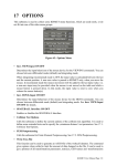
Figure 35: The CAT-Panel
13.2.1
The Monitor/Master-Mode Buttons
• Activate Mechanism:
Selection of the active mechanism which can be a robot or any other kinematic structure.
The selected mechanism is displayed in the active-field.
• Monitor Mode ON/OFF:
Toggle function for activation/deactivation of the joint-position sensor interface between
KISMET and the real robot controller for the active robot.
This function switches to the monitoring-mode. In monitoring mode, KISMET is using the
joint-position sensor data as provided by the real robot controller for synthetic image generation. The workcell display will show the real robots position in the simulated workcell
environment. In this mode, the KISMET display provides the visual interface for man-inthe-loop control of telemanipulation operations, or for surveillance of of automatic (preprogrammed) task sequences. The default state is "OFF".
• Master Mode ON/OFF
In this functional mode, KISMET can be used as a master device (position controller, open
loop) for a real robot controller (graphical master concept). When active, a set of positional
KISMET User Manual Page 70
CAT
data is sent to the controller of the active robot via UNIX-message communications, after
each rendering cycle . An interface program (user generated) is necessary to pick up the
position data from the message queue and to perform the data-distribution to the robot control-hardware. The default state is "OFF".
13.2.2
Camera Simulation & Control
This subpanel is used for control of simulated CAMERA-views and for ONLINE-Control of
"real" workcell cameras during teleoperation.
• Select
This function is used to select the active CAMERA from the CAMERA-menu, which is
automatically generated during model startup. It includes the logical names of all CAMERAs in the application model-database. The active CAMERA has the input focus for all
other commands in the "Camera Simulation & Control" submenu.
• Pointing
Can be used to specify a new 3D-lookpoint (in "top + side view" display mode) for the
"active camera". A single CAMERA motion is carried out.
• View PYRAMID ON/OFF
Enable/disable the overlay of the CAMERA viewing pyramid. The tip of the pyramid is
located at the CAMERA view-location. The base of the pyramid shows the current focal
plane of the CAMERA. The default state is "OFF".
• Tracking ON/OFF
Enable/disable CAMERA-Tracking mode for the active CAMERA (use the "Select
CAMERA"-function to activate a camera). KISMET allows automatic tracking for simulated cameras. The CAMERA must be part of a ROBOT to let this functionality work. It is,
not the CAMERA is moved, but the ROBOT, i.e. the CAMERA motion mechanism. FRAMEs are used as a tracking target. The FRAME to be tracked is PICKed after selection of
this function. Additionally, KISMET calculates the distance (Dist) to the tracking target.
The distance value can be used to implement a model-based autofocus feature (see the command "Send DATA"). The default state is "OFF".
This option can be enabled simultaneously for all CAMERAs in the simulation model. This
is, each camera can be put in TRACKING-mode independant from the other cameras.
• Send DATA ON/OFF
Enable/disable the CAMERA command interface to the camera controller. For monitoring
applications, KISMET can be used to provide high-level kinematic control for the camera
actuators in the real workcell.
A special UNIX-process (communications server) must exist on the workstation to handle
the communications between KISMET and the real controller(s). The default state is
"OFF".
• Dist+Fovy
This valuator function is used for the CAMERA-overlay view to change the two parameters
DIST (focal distance of the real camera) and FOVY (field-of-view angle). When the
CAMERA is in ONLINE-mode, the current parameters are sent to the camera controller.
KISMET User Manual Page 71
CAT
• LM Change DIST attribute
• MM Change FOVY attribute
• BM No function
• MAIN view
The main simulation display (large viewport) is connected with the current position of the
active camera. This function is particulary useful for the generation of animation sequences
(here the camera is defined as a robot and can be controlled by a robot program) or for simulation of camera views in training or monitoring applications. The ’byrdseye view’ parameter dataset will be modified automatically when this command is active.
13.2.3
Framegrabber Control
This subpanel is used for video-framegrabber control. This mode requires the realtime framegrabber ( Live Video Digitizer, Indy Camera, Galileo Board etc.) option in your graphics hardware and the videolab software subsystem installed on your workstation. The submenu allows
optionally the display of a video window or an overlay of a KISMET wireframe-model display
on top of the scanned video camera image. This latter functionality can be useful for model verification against the real workcell and to some extent geometry editing.
• Video Overlay ON/OFF
Enable/disable the realtime video-display. A realtime video channel is opened to the current
system video device (as selected in the SGI system program ’videopanel’). The video image
is rendered on top of the synthetetic workcell view. The video input signal is rendered once
per frame cycle, i.e. the framerate of the video overley is the same as the workcell rendering
framerate. The default state of this function is "OFF".
• GRAPHICS Overlay
Note: You have to define a CAMERA to use this command. The CAMERA-overlay viewport is used to display the FRAMEGRABBER images with the simulated CAMERA wireframe overlay. The active CAMERA view is used for the wireframe model overlay.
Toggles the overlay of the wireframe model drawing on top of the video image. The videoimage is displayed in the CAMERA-overlay viewport. The simulated, virtual CAMERA
view is drawn in wireframe mode as an overlay on the scanned video-image. This is, the
function is possible only if at least one CAMERA is defined in the workcell model. The
simulated wireframe and the real image correspond, if the view parameters of the simulated
CAMERA are similar to the view attributes of the real camera. These values have to be set
once for the simulated CAMERA, using the CAMERA submenu (to set the FOVY parameter) and the motion commands (to adjust the CAMERAs pitch/roll/yaw parameters). If the
virtual CAMERA is not actuated, i.e. the CAMERA itself is not actuated or its actuators are
not defined as a ROBOT in the KISMET-model, you can use the "Edit FRAME" commands
to adjust the viewing position and -direction of its reference FRAME.
• RESET
Resets the FRAMEGRABBER hardware to its default parameters.
• Param. SET
This command displays a form-window, which allows to set all hardware parameters of the
KISMET User Manual Page 72
CAT
video framegrabber during runtime. See the videopanel(1) manual page of your SGI workstation and the documentation of the Live Video Digitizer about further details about these
parameters.
KISMET User Manual Page 73
14 DETAIL
14.1. Introduction to the KISMET DETAIL-LEVEL Concept
This chapter describes the DETAIL submenu, visible for the user while executing KISMET in
the non-full-screen-mode. In full-screen-mode a different user interface using pop-up menus
will appear. The corresponding menu-names are surrounded by {}.
In KISMET a hierarchical, recursive, tree like data model is used. The operator can specify interactively and on-line the level of detail to be displayed. Components or model parts can be
activated or deactivated for display at any time. This allows to render higher levels of detail without loss of realtime performance. There is no logical limitation on the number of detail-levels
or model size.
Figure 36 shows the rendering of a flange assembly (from the CATROB model) in two different
detail levels.
Figure 36: Workcell dipslay using DETAIL-LEVELS
A bounding box which is used to mark a non-accesible area is rendered in the left picture, whereas the right image shows the detailed rendering of the flange assembly after switching the detail level.
To achieve the detail-leveling functionality in KISMET, we use a hierarchical, tree-like structure of ABSTRACT files. Each ABSTRACT file defines an arbitrary number of FRAME records. Now, every FRAME can reference another ABSTARCT-file, called the "son"-file. This
is, you can define any numbers of "sons" from one ’.mpc’ file. Figure 37shows the tree-like
structure of ABSTRACT files (’.mpc’), as used in KISMET.
KISMET User Manual Page 74
DETAIL
Figure 37: Hierarchical Structure of ABSTARCT-Files
14.2. DETAIL Submenu {Edit ABSTRACT}
The DETAIL submenu is used
• to load, activate and deactivate model-parts and details and
• to create an new (robot) model.
In KISMET, an ABSTRACT is a kind of special FRAME, which acts as a reference for an assembly, or to another, more detailed representation of the part. The physical representation of
the ABSTRACT is a file (’.mpc-file’) which defines a part with its FRAMES and file-references
to the GEO- element data (’.mpo-files’). An ABSTRACT-file is also used to define exactly one
KISMET User Manual Page 75
DETAIL
ROBOT.
Figure 38: The Detail Submenu
As a special feature in KISMET, each frame defined in an ABSTRACT file can store the file
reference to another ABSTRACT file. This feature is used to define multiple levels of detail in
KISMET. It is possible to control the simulation performance (frame rate) over a wide range in
KISMET, using this feature. To get the optimum performance, you should only activate those
parts and details of the application model which are necessary for operation in the current stage
of the simulation. The following section explains the different commands in the „DETAIL“
Submenu.
• Pick Frame {Pick ABS_Node}
This command is used to start a PICK operation to identify the ABSTRACT node for successive operations. An ABS-node is picked at the origin of its associated coordinate system
as drawn in the workcell display. When an ABSTRACT is picked, all GEO-parts connected
to this ABSTRACT are highlighted
• Pick GEO{Pick ABS_NODE via GEO}
This is another command to PICK an ABSTRACT. It is computationally more demanding
as the previous command. Here you can pick an ABSTARCT by picking any GEO-part connected to this ABSTRACT, i.e. to all FRAMES in the ABSTRACT file.
• Activate{Activate ABS-Branch}
A previously deactivated ABSTRACT is activated for display. All GEO-parts connected to
the reference FRAME of the ABSTRACT remain active for display (see ’Swap Level’ command).
• Deactivate{Deactivate ABS-Branch}
An active ABSTRACT branch is deactivated for display. This command is useful to
KISMET User Manual Page 76
DETAIL
increase drawing speed (frame rate) drastically in the simulation. You should deactivate all
model parts which are currently not essential for the operation. The ABSTRACT branch is
not removed from the runtime database (main memory). Therefore it can be reactivated
immediately for display by an ’Activate’ operation.
• Load{Load ABS-Branch}
Another ABSTRACT branch is loaded from the model database and activated for display.
The memory required for model storage is allocated from the operating system. The
function is used to load a model part or detail level which is marked in the database (’.mpcfile’) with the ’W’ attribute (wait), or to reload parts which were deleted previously in the
same simulation session.
• Swap LEVEL{Swap DETAIL Level}
This command loads/activates the next detail level (more detailed) for the picked ABSBranch. At the same time, all GEO-parts connected to the reference frame of the
ABSTRACT are deactivated for display. This is, the current GEOMETRY of the
ABSTRACT-frame is replaced by a more detailed alternative geometry, which is defined in
the loaded ABSTRACT-file (’.mpc file’).
• More GLOBAL{More Details}
This command is used to increase the detail level for the whole application model by one.
The command works similar like a set of ’Activate’ or ’Load’/’Swap LEVEL’ commands.
Only, it works with the whole model. It is mainly for „lazy“ operators. Using this function,
there is no fine control concerning which parts to load/activate/swap or not. You may find
for some models, that the performance is reduced drastically after using this command. This
can happen when to many parts (more than expected) are activated.
• Save as{Write ABS_FILE}
This function is used to save changes in the model to the file system. After picking an
ABSTRACT (and the corresponding ’.mpc file) using the ’Pick’ Frame’ or ’Pick GEO’
command, the identified ABSTRACT is written to the database. Since an ’mpc file’ can
have file references to other mpc-files and one ’.dof’-file, the user has different options:
Figure 39: The Save-as Panel
• Update dof-file:
The referenced dof file is checked and updated if necessary. KISMET checks, whether
each moveable frame in the picked mpc-file is referenced in the dof-file or not. If a
moveable frame is not referenced, the dof-file will be updated using the following
default values (for frame No. i):
<menu_text> ::= „name_of_frame“_DOF
<outp_text> ::= Z_i
<n_entries> ::= 1
<type> ::= 0
KISMET User Manual Page 77
DETAIL
n_const ::= 1
<const> ::= 0.1
(see User Data Specification).
• Update mpc-file
The referenced mpc-file will be updated.
• Update both
The referenced ’dof-’ and ’mpc’- file will be updated.
• Update none
Only the picked mpc-file will be updated, none of the referenced mpc- or dof-file will
be updated.
• Save ROOT{Write ABS-Root File}
The ABSTRACT-root, i.e. the uppermost ’.mpc’ file in the application model, is written to
the file system.
• Unload{Delete ABS-Branch}
Deletes an ABSTRACT-branch from the runtime database (main memory): The reference in
the current model is not changed or deleted. This is, the abstract can be reloaded later in the
simulation session. The function is useful to make space in the main model for other parts,
for example to avoid memory swapping. It is also used to increase drawing performance.
• Delete REFERENCE{Delete ABS-Reference}
Removes a REFERENCE to an ABSTRACT-file from the specified (picked) node. From
this moment, the ABSTRACT file (detail or assembly) cannot be loaded or activated in the
current simulation session. The abstract file in the database is not affected by this operation,
because it may be referred to in other application models or parts of the current model
(instancing).
• Print NODENAME{Print Nodename}
the fully qualified nodename of the ABSTRACT is printed in the KISMET-textport. The
nodename is a list of all FRAME-names from the model-root (ABS-ROOT) to the selected
ABSTRACT. The abstract names are separated by a ’.’ (dot). The full qualified nodename is
used in SCRIPT-files to uniquely identify a FRAME or ABSTRACT node. This naming
convention is necessary, because KISMET allows instancing of GEO-parts, FRAMEs and
ABSTRACT-files.
• Create Robot
A new model is created: Starting with the ’.sim-File’ and leading the user through the complete data structure a new model will be created. This command can be used for example to
give an existing modell a new name after changes have been made.If no ’dof-’file is available in the current model, a dof-file will be generated automatically.
KISMET User Manual Page 78
DETAIL
Usage:
Create robot opens the Enter sim file name panel:
Figure 40: The Enter-Sim-file Panel
The next step will lead you to the Enter mpc-base name Panel:
Figure 41: The Enter base_mpc file name panel
Finally the menu gives you the possibility to update and save all mpc-files of the current
model. The Save as Panel will appear (see Figure 39: The Save-as Panel).
KISMET User Manual Page 79
15 MODEL
15.1. Introduction to the MODEL-submenu
This menu contains submenus responsible for
•
•
•
•
editing and changing of geometric parts (Edit GEO)
creating and moving of frames (Edit FRAME)
editing colour tables (Edit COLOUR)
editing tables defining surface properties (Edit MATERIAL)
Figure 42: The Cell Modeling Panel
15.2. Edit GEO
The "Edit GEO" submenu is used for local creation, positioning and editing of geometry parts
(GEO-elements). Together with the "Edit FRAME" menu it provides the basic interface for model creation, or local model correction during on-line remote handling sessions. The basic concept behind KISMET is to import geometry parts from CAD-systems. Although, in some
situation the build-in geometry editor can be useful. Geometry placement operations (translate,
rotate) are performed with a local copy of the GEO-element. This is, you have to CONFIRM
the modification of the PLACEMENT when you are done with a GEO-part. The current GEOobject is highlighted after identification (PICK).
Figure 43: Edit GEO
• Pick
This command is used to start a PICK operation to identify the GEO-part to be edited. You
KISMET User Manual Page 80
MODEL
may PICK the part at its surface area. However, picking is faster if you use the pickingREGION, i.e. the little white square which is drawn approximately in the centre of the
GEO-part.
• CONFIRM
This command is used to confirm any changes during GEO-placement editing ("Rotate" and
"Translate"). These operations are carried out with local copies of the operand.
• Rotate
The GEO-part is rotated in 3 dimensions relative to its reference FRAME. A general 6 parameter transformation (dx , dy , dz , α, β , γ ) is used by KISMET for the transformation.
• LM Change αG , i.e. rotate GEO around X-axis
• MM Change βG , i.e. rotate GEO around Y‘-axis
• BM Change γG , i.e. rotate GEO around Z‘‘-axis
• Translate
The GEO-part is translated relative to its reference FRAME in 3 dimensions.
• LM Translate GEO about dx along FRAME-X-axis
• MM Translate GEO about dy along FRAME-Y-axis
• BM Translate GEO about dz along FRAME-Z-axis
• SCALE xyz
Scales the GEO-part along the
• X-Axis, if LM is used,
• Y-Axis, if MM is used
• Z-Axis, if BM is used.
• SCALE all
Scales the GEO-part along the X-, Y- and Z-axis.
• Morphing
Activates the interactive morphing funtion, i.e. a linear interpolation of a geometric part into
a similar part with different shape is performed.
• Edit Flex
Leads to the Edit Flex subpanel. See chapter 15.2.1 Edit Flex.
• READ
This command inserts a GEO-element into the model. KISMET requests you to pick the
reference FRAME for the new part. The new element is connected to this FRAME. To select a certain GEO the File selction panel will pop up to offer you a selection of ’mpo-files’.
• DUPLICATE
KISMET User Manual Page 81
MODEL
The function is used to copy the previously picked GEO-element. KISMET requests you to
pick the reference FRAME for the copied part. The instanced element is connected to this
FRAME. An identical copy (instance) of the part is used.
• CREATE
This command is used to create (model) a new 3D GEO-part, which is added to the model.
The selection of the GEO-primitive is carried out in an upcoming submenu. The parameters
are entered in a form window. A special form is available for each primitive. The dimension
for modelling is ‚mm‘. The new GEO-part is connected to a reference FRAME. KISMET
will ask you to PICK the FRAME, so make sure, that the FRAME is visible in the current
viewport when the CREATE command is used. Each GEO-part is stored as an ASCII-file in
the model database in the directory $kis_home/mpolib. The standard suffix for GEO-files is
‚.mpo‘.
The following list of basic primitives is available in the "Primitive"-submenu:
Figure 44: The Primitive Submenu
The 2D-geometry editor 2Ded is called for the interactive definition of the sweep contour
when the SWEEP-primitives are selected for modelling. The contour is defined from segments, using POLYLINE, ARC, and B-SPLINE 2D-modelling elements. The 3D-surface is
formed by a translation (linear sweep), or rotation (rotational sweep), respectively. See
chapter 21 The 2Ded-Editor for SWEEP Operations for details.
The newly created parts can be used with the BOOLEAN-operations to form more complicated GEO-parts. The results are saved as POLYHEDRON models.
• DELETE
The selected (picked) GEO is deleted from the datatree. The operation is carried out in the
runtime model. To delete a part from the file system, use the UNIX command ‘rm‘.
• Edit NURB
Leads to the "Edit Nurb" submenu. See chapter 15.2.2 Edit NURB.
• DRAWMODE
KISMET User Manual Page 82
MODEL
Determines the drawmode for the picked GEO-part.
Figure 45: GEO Drawmode
• Transparent
The picked GEO-part is drawn in TRANSPARENT-mode. All other parts keep the
previous drawing mode. This function sets an attribute in the model datastructure.
This attribute is reset when a "Drawmode" command is executed. Note: The transparent drawing mode in KISMET is using the α-bitplanes. On workstations with limited
graphics hardware, using this command can give unpredictable results.
• Wireframe
The picked GEO-part is drawn in WIREFRAME-mode. All other parts keep the previous drawing mode. This function sets an attribute in the model datastructure. This
attribute is reset when a "Drawmode" command is executed.
• Flat Shaded
See chapter 9.2. The Display Panel for further information.
• GOURAUD Shaded
See chapter 9.2. The Display Panel for further information.
• INVERT Faces
The orientation of all polygonal facets of the selected GEO-part is reversed.
• Interpolate Normals
Interpolates smooth normal vectors on the polygon edges of the selected GEO-part. KISMET will ask for the maximum angle between the adjecent facets to be used for smoothing.
• CSG Operation
This command is used for interactive execution of Boolean Modelling Operations. After the
command is selected, you have to PICK the two parts (OPERANDS) for the following boolean operation. The type of boolean operation (Union, Difference, Intersection) will be
requested by KISMET. The operands will not be effected by the calculation. The calculation
is carried out with local copies of the operand parts.
The computation is carried out on the basis of the KISMET-internal, facetted polyhedronmodel. The operation is not restricted to a subset of the available GEO-primitives. For successful computation the operands should have a closed surface shell (solid-parts). The operands should intersect eachother to achieve satisfying results.
• Write POLYHEDRON
The picked GEO-part is saved in the file ‚$kis_home/mpolib/<filename>‘ as a POLYHE-
KISMET User Manual Page 83
MODEL
DRON model. The parameter <filename> is entered by the user. Note: The default extension of GEO-partfiles is ‚.mpo‘. This extension is used by KISMET in the file selection
panel.
• Write EXT_POLYHEDRON
The picked GEO-part is saved in the file ‚$kis_home/mpolib/<filename>‘ as an
EXTENDED_POLYHEDRON model. The difference to an ordinary polyhedron is, that for
each surface vertex a surface normal is stored in the model. This form of storage should be
used for parts with smoothly curved surfaces, to allow for GOURAUD-shading when you
recall the model. The parameter <filename> is entered by the user. Note: The default extension of GEO-partfiles is ‚.mpo‘. This extension is used by KISMET in the file selection
panel.
• Save all GEOs
Saves every GEO in the current model.
15.2.1
Edit Flex
This submenu is used to manipulate geometric primitives of the id '90' (KISMET GeometrySpecification: ELADYN_NURBS) as well as id ’91’ (KISMET Geometry-Specification:
ELADYN_POLY). The elastodynamic behaviour can be controlled and influenced, parameters
can be adjusted. Some items in this submenu can also be used for manipulating other flexible
parts (sub-id '-10' in the KISMET Geometry-Specification).
The 'Edit FLEX' - Submenu is located under the main menu 'MODELS' - 'Edit GEO'. For some
operations, the specific geo part must be identified first ('PICK Geo', marked with (P_GEO) in
following description). The submenu consists of 11 buttons:
Figure 46: Edit FLEX
• Pick CP (P_GEO)
A specific mass knot of the ElaDyn-Object can be selected. After the identification of the
GEO, all mass knots are highlighted (white tetraeder). The desired mass knot can now be
picked with the mouse (left mouse-button). The coordinates of the knot are printed out in
the textport. For some operations, a specific knot must be identified first with this feature
(marked with (P_CP) in following descriptions).
• Move CP (P_GEO) (P_CP)
The selected mass point can be moved by the mouse.
A horizontal movement shifts the knot:
KISMET User Manual Page 84
MODEL
- in x-direction, if the left mouse button is pressed
- in y-direction, if the middle mouse button is pressed
- in z-direction, if both mouse buttons are pressed
The coordinates of the knot are printed in the lower left edge of the viewport.
• Fix CP (P_GEO) (P_CP)
The selected mass knot is fixed. All bounding conditions are activated, the knot can't move
any more until the knot is released.
• Release CP (P_GEO) (P_CP)
The selected mass knot is released. All bounding conditions are deactivated, the knot can
move in any direction.
• Freeze
All elastodynamical calculations are stopped. All flexible parts are 'freezed' until the button
is pressed again (Toggle-Button).
• Reinit Flex (P_GEO)
The elastodynamical properties of the geo are reinitialized. This feature is useful for interactive geometric changes. First, the geo is freezed, then the knots can be moved to change the
geometric shape. Last, the elastodynamic object is reinitialized.
• Add Force (P_GEO) (P_CP)
An external force can put on the selected mass knot.
A horizontal movement of the mouse changes the force in a specific direction:
- in x-direction, if the left mouse button is pressed
- in y-direction, if the middle mouse button is pressed
- in z-direction, if both mouse buttons are pressed
The current force-values in each direction (unit: Newton) are printed out in the lower left
edge of the viewport.
• No Forces (P_GEO)
All external forces of the selected object are set to zero.
• Calculation
Opens the calculation-window, where all the parameters of the elastodynamic calculation
KISMET User Manual Page 85
MODEL
can be set and changed:
Figure 47: The Calculation-Panel
• calc. repeat fact (number, unsigned)
number of repetitions of the elastodynamical calculation before new drawing
• time step (number, float)
Integration time for the elastodynamical calculation (only required if time step definition = Const.)
• time step def.(Bool, Auto/Const)
Switch Real Time/Constant Time
• Motion Calc.(Bool, Real/Slow)
Switch Real Time/Slowmotion (10*, used to prevent numerical instabilities)
• Dynamic Calc.(Bool, Real/Quasi)
Switch complete dynamic calculation/simplified dynamic calculation
• ElaDyn Type (Bool, I/II)
Switch elastodynamical options
• Object move (Bool, On/Off)
Switch global object move
• Gravity (Bool, On/Off)
Switch gravity. The direction of the gravity vector points along the negativ y-axis in
world coordinates (9,81 m/s2). Only geo-objects with the Kismet-id 90 are influenced
by the gravity.
• Ground (Bool, On/Off)
• Switch ground (y=0 plane)
• Draw Poly (Bool, Yes/No)
KISMET User Manual Page 86
MODEL
•
•
•
•
Switch drawmode: polygonal drawing
Draw NURBS (Bool, Yes/No)
Switch drawmode: NURBS drawing
Parameter (P_GEO)
Opens the parameter-window, where all the specific parameters of an elastodynamic
object can be set and changed (all parameters are floats):
Figure 48: P_GEO Parameter Panel
• geo-knot mass
mass of knots with geometrical link (outer knots), defined in [kg]
• object mass
mass of the whole elastodynamic object [kg] (mass of all inner knots)
• knot damp
damp factor of the elastodynamical mass knot, defined in [Ns/m]. The damp
force is proportional to the damp factor and the velocity of the refered knot.
• object damp
damp factor of the elastodynamical system, defined in [Ns/m]. Used for global
movements
• geo-springs stiff
spring constant of the springs which links the geometrical knots
Two kinds of spring characteristics are implemented:
sconst > 0 : spring force is proportional to the spring length [N/m]
sconst < 0 : spring force is proportional to the quadratic spring length [N/m2]
• basic-springs stiff
spring constant of the springs which force the knots to the original positons(retursprings), maintain the original shape of object
Two kinds of spring characteristics are implemented:
sconst > 0 : spring force is proportional to the spring length [N/m]
sconst < 0 : spring force is proportional to the quadratic spring length [N/m2]
KISMET User Manual Page 87
MODEL
• object-spring stiff
spring constant of the springs with global links (inner knots, connections)
Two kinds of spring characteristics are implemented:
sconst > 0 : spring force is proportional to the spring length [N/m]
sconst < 0 : spring force is proportional to the quadratic spring length [N/m2]
• torque-spring stiff.
spring constant of the torque-springs of inner knots, defined in [Nm]
(maintains the global orientation of the knot)
• Show Parts
The components of all elastodynamic objects are shown. Mass knots are drawn as coloured
tetraeders with their specific number (the colour is dependend from their interaction status),
springs are drawn as green lines. Additionally, the sum of the inner forces of each mass knot
are shown as red vectors, and the shift of the mass knots relative to there equilibrium positions ist displayed in orange. The direction of each inner knot is visualized as a blue arrow.
• Save ElaDyn (P_GEO)
The selected elastodynamic part is saved in a Kismet geo-file ('*.mpo'). The name of the file
must be specified in the textport.
• Quit
The submenu is been closed.
15.2.2
Edit NURB
This submenu is used to manipulate geometric primitives of the id '80' (KISMET GeometrySpecification: NURBS) as well as id ’90’ (KISMET Geometry-Specification:
ELADYN_NURBS). NURBS (Non-Uniform Rational B-Spline Surface) are free-form surface
represented by a matrix of characteristic points, the controlpoints. The shape of the geometry
can be influenced by shifting the positions of the controlpoints. The 'Edit NURBS' - Submenu
is located under the main menu 'MODELS' - 'Edit GEO'.
Figure 49: Edit NURB
For some operations, the specific geo part must be identified first ('PICK Geo', marked with
(P_GEO) in following description), other operations need a specified knot (’Pick CP’, marked
with (P_CP) ), too.
The submenu consists of 7 buttons:
KISMET User Manual Page 88
MODEL
• Pick CP (P_GEO)
A specific controlpoint of the NURBS-Object can be selected. After the identification of the
GEO, all controlpoints are highlighted (white tetraeder). The desired controlpoint can now
be picked with the mouse (left mouse-button). The coordinates of the point are printed out
in the textport.
• Move CP (P_GEO) (P_CP)
The selected controlpoint can be moved by the mouse.
A horizontal movement shifts the controlpoint:
- in x-direction, if the left mouse button is pressed
- in y-direction, if the middle mouse button is pressed
- in z-direction, if both mouse buttons are pressed
The coordinates of the point are printed in the lower left edge of the viewport.
• Move ROW (P_GEO) (P_CP)
The whole row of the selected controlpoint can be moved by the mouse.
A horizontal movement shifts the row:
- in x-direction, if the left mouse button is pressed
- in y-direction, if the middle mouse button is pressed
- in z-direction, if both mouse buttons are pressed .
• Move COL (P_GEO) (P_CP)
The whole column of the selected controlpoint can be moved by the mouse.
A horizontal movement shifts the column:
- in x-direction, if the left mouse button is pressed
- in y-direction, if the middle mouse button is pressed
- in z-direction, if both mouse buttons are pressed
• Save ElaDyn (P_GEO)
The selected NURBS object is saved in a Kismet geo-file ('*.mpo', KISMET-ID ’80’). The
name of the file must be specified in the textport.
• Drawmode (P_GEO)
The drawmode of the selected NURBS can be defined (Filled, Outline Poly, Outline Patch,
Isolines)
• Done
The submenu is been closed.
15.3. Edit FRAME
15.3.1
Introduction to "Edit Frame"
The kinematic structure in this part of KISMET is regarded as being composed of rigid links
connected by joints with contact along a surface, a curve or in a point. Robot kinematics deals
with the geometry of robot link motion with respect to a fixed-reference coordinate system as a
KISMET User Manual Page 89
MODEL
function of time without regard to the forces and moments that cause this motion. It deals with
the spatial configuration of mechanisms, in particular with the relations between the joint variables and the position and orientation of a robot end-effector. The kinematics problem consists
of the direct and the inverse kinematics subproblems.
Further parts of this document extend this basic schema with an extended model, to allow for
simulation of
• elastostatic effects, this is torsion and bending of flexible links
• robot arm dynamics
• control algorithms
For the purpose of clarification of the following sections, a list of definitions is given in this section. The definitions are given in alphabetical, not in logical or topological order.
ABSTRACT
represents all data associated with a FRAME. This is, it defines also the topological relations used for the purpose of detail
levels. It includes the definition of a FRAME itself, the references to the SHAPE (GEO-element) data together with the
relative PLACEMENT of the SHAPE elements with respect to
the ABSTRACT-FRAME.
AXIS_PLACEMENT
defines a fixed relative position and orientation of one coordinate system with respect to another coordinate system. For the
purpose of term simplification, this term is mostly called PLACEMENT.
BASE
represents a link, which is fixed to the WORLD system or
whose motion is prescribed by the motion of another ROBOT.
DOF
defines the relative motion between two FRAMEs of a JOINT
by locking some spatial degrees of freedom (DOF) and establishing parameters for the unconstrained degrees of freedom.
FRAME
is a specific kind of coordinate system attached to a kinematic
such as WORLD, BASE, JOINT or LINK. Different ways of
specifying the placement of a FRAME relative to another are
possible.
JOINT
connects two LINKS and constraints the relative motion of
one LINK to another via a DOF. A JOINT is kinematically
defined by a FRAME which defines the axis of motion, and
another moving FRAME which is connected to the LINK.
LINK
rigid body whose motion is constrained by one or more
JOINTs.
WORLD
defines the reference coordinate FRAME of the workcell
simulation. All relative motions of FRAMEs can be expressed
by a chain of PLACEMENT transformations in WORLD
coordinates.
KISMET User Manual Page 90
MODEL
15.3.2
The "Edit Frame" Panel
The "Edit FRAME" submenu is used for local creation, positioning, and editing of sub-assembly references (FRAMEs) and actuated JOINTS. It provides the basic functions for kinematic
modelling.
In KISMET, a FRAME can be a robot BASE, JOINT or LINK reference coordinate system, or
simply a reference system for part assemblies. The FRAMEs are grouped in a hierarchical model tree, which builds the kinematical sceleton of the workcell. All other objects and primitives,
such as GEO-elements (shape geometry), robot TCP and ZP, CAMERAs, sensors, workframes
(WFRM: the equivalent to the robot TCP on passive workcell parts) etc., are kinematically connected to the FRAMEs. In the first place, a FRAME is the property of a 3D coordinate system.
Additionally, each FRAME has a name (identifier), a reference to other FRAMEs for the definition of kinematics and assembly-level topology, and other parameters, depending on the nature of the FRAME.
Figure 50: The Edit Parts (FRAME) Panel
• Pick FRAME
This command is used to start a PICK operation to identify the FRAME to be edited. A
FRAME is picked at the origin of its coordinate system as drawn in the workcell display.
When a FRAME is picked, this is activated for editing, all GEO-parts connected to this
FRAME are highlighted.
• Pick GEO
This is another command to PICK a FRAME. It is computationally more demanding as the
previous command. Here you can pick a FRAME by picking any GEO-part connected to
this FRAME.
• Rotate
The FRAME is rotated relative to its kinematic predecessor FRAME. For modelling FRAMES (type>= 50) with a general 6 parameter transformation (dx , dy , dz , α , β , γ ) , you
may rotate the FRAME in 3 dimensions, whereas for JOINT-FRAMES (type <= 3) the
Denavit-Hartenberg (DH) notation ( ai , αi , θi , di ) is used. This is, you can rotate the
JOINT-FRAME in 2 dimensions ( ai , θi) only.
For modelling-FRAMES (type >= 50):
• LM Change ai , i.e. rotate FRAME around X-axis
KISMET User Manual Page 91
MODEL
• MM Change bi , i.e. rotate FRAME around Y‘-axis
• BM Change gi , i.e. rotate FRAME around Z‘‘-axis
For JOINT-FRAMES (type <= 3):
• LM Change θi..This is the joint angle from the xi-1 axis to the xi axis about the zi-1
axis.
• MM Change αi. This is the offset angle from the zi-1 axis to the zi axis about the xi
axis.
• BM No function
• Translate FRAME
The FRAME is translated relative to its kinematic predecessor FRAME. For modelling
FRAMES (type >= 50) with a general 6 parameter transformation (dx , dy , dz , α , β , γ ) ,
you may translate the FRAME in 3 dimensions, whereas for JOINT-FRAMES (type <= 3)
the Denavit-Hartenberg (DH) notation ( ai , αi , qi , di ) is used. This is, you may shift the
JOINT-FRAME in 2 dimensions only.
For modelling-FRAMES (type >=50):
• LM Change dx, i.e. translate FRAME along X-axis
• MM Change dy, i.e. translate FRAME along Y-axis
• BM Change dz, i.e. translate FRAME along Z-axis
For JOINT-FRAMES (type <= 3):
• LM Change di. This is the distance from the origin of the "S"i coordinate frame to
the intersection of the zi-1 axis with the xi axis along the zi-1 axis.
• MM Change ai. This is the shortest distance between the zi-1 system (i.e. the rotation
axis) and zi axis.
• BM No function
• Show FRAMEs
This function is used to activate the display of all frames in the current workcell. The FRAMES are displayed as a coordinate frame and with the logical name.
• Drawmode:
Determins the drawmode of the GEO-parts belonging to the picked FRAME.
Figure 51: FRAME Drawmode
• Transparent
All GEO-parts of the picked FRAME are rendered in TRANSPARENT-mode. All
KISMET User Manual Page 92
MODEL
other parts keep the previous drawing mode. This function sets an attribute in the
model datastructure of the GEO-parts. The attribute is reset when the next global
"Drawmode" command is executed. Note: The transparent drawing mode in KISMET
is using the α-bitplanes. On workstations with limited graphics hardware, using this
command can give unpredictable results.
• Wireframe
All GEO-parts of the picked FRAME are rendered in WIREFRAME-mode. All other
parts keep the previous drawing mode. This function sets an attribute in the model
datastructure of the GEO-parts. This attribute is reset when the next global "Drawmode" command is executed.
• FLAT Shaded
All GEO-parts of the picked FRAME are rendered in FLAT- shaded mode.
• GOURAUD Shaded
All GEO-parts of the picked FRAME are rendered in GOURAUD- shaded mode.
• Create FRAME
A new FRAME is added to the workcell. All necessary parameters are requested by KISMET in an interactive dialogue. You have to PICK two FRAMEs after the command is executed. The first FRAME defines the ABSTRACT-file, i.e. the branch in the model tree
where the new tree will be stored when you save the workcell. The second FRAME to be
picked defines the kinematic predecessor. The new FRAME will move together with its predecessor.
For all FRAMEs (JOINTS and modelling), you have to specify a name. This is a textstring,
which is used for identification by some textual commands (SCRIPT-commands). For JOINTs
(FRAME types: 0,1,2,3), you have to enter additionally the basic kinematic parameters min-,
max joint angle (motion limits), max. velocity and max. accelleration.
• Connect
The kinematic predecessor of a FRAME is set to a new frame. From this moment the reconnected FRAME and all its kinematic successors are kinematically connected the the new
location. This is, the command is used to change the kinematic topology. The placement of
the reconnected frame in absolute workcell coordinates (world) is not modified through this
function.
For example, it is used when a tool-exchange is to be performed. Move the robot to the toolbox and the location of the tool. Then reconnect the reference FRAME of the tool with the
toolbox reference system. The tool will stay in the toolbox when you move the robot. Next
move the robot hand to the new tool at its location in the toolbox. Reconnect the tool reference FRAME with the robot hand FRAME. When the robot is moving, the new tool will be
connected with the robot hand.
• connect GEO
A GEO-element is reconnected to a new reference FRAME. The placement of the reconnected GEO in absolute workcell coordinates (world) is not modified through this function.
• to WFRM
This command is used to reconnect a FRAME with all its associated parts and objects to a
KISMET User Manual Page 93
MODEL
new reference system. The target location is defined in this case by a workframe (WFRM).
See also the "Reconnect FRAME" command.
You can use this function to perform a tool exchange without moving to the exact locations
of the new reference positions of the FRAME-assembly. The reconnected FRAME will
"jump" to the new reference location. You have to define a WFRM at the target positions.
• Successor
A new kinematic successor FRAME is assigned to the picked FRAME. This command is
useful for joint types 2 and 3. These types are used within closed kinematic loops.
• Add ABSTRACT
A reference to another ABSTRACT-file (i.e. a subassembly, a ROBOT- or DEVICE-mechanism, or another DETAIL-level) is added to the FRAME node. In any case, the ABSTRACT
reference is in fact an ‚.mpc‘ file. The ABSTRACT-file must already exist in the model
database, i.e. in ‚$kis_home/mpclib‘. The file is identified by picking in the file panel.
The user must specify the initial read-status of the new ABSTRACT-reference. There are
two choices, either initial "READ" or "WAIT". This is:
• READ the file is opened immediately, all substructes are loaded and activated for display.
• WAIT only the reference to the file (name) is added to the model-tree. The new file
will be loaded on user request. For this, refer to the commands:
•"Activate"
•"Load"
•"Swap LEVEL"
•"More GLOBAL"
in the "DETAIL" submenu. Similar commands are available in the SCRIPT interface.
• Print Nodename
The fully qualified nodename of the FRAME is printed in the KISMET-textport. The nodename is a list of all FRAME-names from the model-root (ROOT-FRAME) to the selected
FRAME. The frame names are separated by a ‚.‘ (dot). The full qualified nodename is used
in SCRIPT-files to uniquely identify a FRAME or ABSTRACT node. This naming convention is necessary, because KISMET allows instancing of GEO-parts, FRAMEs and
ABSTRACT-files.
15.4. Edit COLOUR
KISMET is using two tables for lighting and/or shading. An RGB colour table which is used for
wireframe drawing (no lighting), the background and everything around the workcell display.
Another table is used for MATERIAL definitions. A MATERIAL defines the basic colour and
the reflection parameters of GEO-surfaces. The two tables are, with some limitations, user defineable. They are set in the colour (extension ‚.col‘) and material (extension ‚.mat‘) files, re-
KISMET User Manual Page 94
MODEL
spectively. See also chapter 15.5. Edit Material.
Figure 52: The Colour Editing Panel
Set PANEL
The setings of the current colour are used for the panel background (i.e. for the user interface).
Set Background
The selected colour is used as background colour for all views.
Pick GEO
Selects the GEO part, the colour of which should be changed.
Set Wire COL
Sets the wireframe colour of a selected GEO-part.
RGB/HLS
Allows the modification of the
• colour parameters R,G and B (Red, Green and Blue- according to the RGB-colour model)
• or the colour parameters H, L and S (Hue, Lightness, Saturation - according to the HLScolor model).
The current MATERIAL-index (see "Set MATERIAL Index" command) is used.
Index
Shows the index of the currently selected colour for editing. This number corresponds to the index in the KISMET colour file (.col)
DONE
The colour editing window will be closed
APPLY
The whole colour table as edited is transferred to the scene (until now all colour modifications
are local to the colour editing window).
KISMET User Manual Page 95
MODEL
SAVE
The whole colour table as edited prviously is transferred to the scene (until now all colour modifications are local to the colour editing window). Additionally a colour file (.col) is saved to
the harddisk, i.e. this function is used for permanent changes to the models colour table.
15.5. Edit Material
Figure 53: MATERIAL Editing
• Index
The index corresponds to the material definition in the ‚.mat‘ file.
• Pick MATERIAL
Selects the MATERIAL index to be edited from the scene window. You have to pick a
GEO-part from the scene window. The MATERIAL parameters associated with this GEOpart (and possibly some other parts) will be subsequently modified using the sliders.
• PICK GEO
This command is used to identify a GEO-part in the main scene window. The MATERIAL
index as selected in the MATERIAL will be attached to the GEO-part as picked, when the
Set MATERIAL button will be pressed subsequently..
• Set MATERIAL
The currently selected MATERIAL is attached to the selected GEO-part. Use the PICK
GEO button to select the part
• Kp, Ks, Kd
Allows modification of the MATERIAL parameters Kd, Ks and Kp. (coefficients for Diffuse Reflection, Specular Reflection, Specular Power).
• S, L, H
Allows modification of the MATERIAL parameters S, H and L. (coefficients for Saturation,
KISMET User Manual Page 96
MODEL
Hue and Lightness) according to the HLS colour model..
• DONE
This button is used to terminate MATERIAL editing mode. The MATERIAL window will
be closed. No changes will take effect in the scene window unless you have pressed the
APPLY button before.
• APPLY
The whole MATERIAL table as edited is transferred to the scene (until now all modifications are local to the editing window).
• SAVE
The whole MATERIAL and COLOUR tables as edited are transferred to the KISMET
scene (until now all modifications are local to the colour editing window). Additionally the
MATERIAL and COLOUR files (.mat and .col) are saved to the harddisk, i.e. this function
is used for permanent changes to the models MATERIAL table.
KISMET User Manual Page 97
16 DYNAMICS
16.1. Introduction to "Elastomechanics"
16.1.1
Elastomechanics Basics
KISMET provides the posibility to calculate the static deflections of a robot in real time. Therefore it is required to expand the robot model, i.e. to provide the necessary data-sets. In order
to extend the model, there are 3 frametypes, which have to be integrated into the kinematical
model and enable KISMET to fulfill the task.
Figure 54: Rigid and non-rigid kinematical chains
Figure 54 shows two links of a kinematical chain, connected by a revolute joint in the rigid and
non rigid case. The matrices A i are the relative transformation matrices between two joints in
the stiff case, while the Ei denote the relative transformation matrix between a joint in the "flexible" case and the same joint in the rigid case.
To enable KISMET to show both cases alternatively, the rigid model of a robot or a kinematical
chain has to be extended as shown in figrue 54. Two main steps have to be done by the user:
1. A frame c̃ i must be created and connected with the frame ci. Frame ci indicates the position
and orientation of joint i in the rigid case, while c̃ i is responsible for the nonrigid case.
2. The order of succession of the frames has to be changed for the nonrigid case. While frame
ci is the predecessor of frame ci+1in the rigid case, frame c̃ i is the predecessor in the nonrigid case. KISMET provides two data sets, to calculate and show the robot in the rigid and
non rigid case simultaniously.
In the next chapter the necessary steps for extending an existing robot model is shown in detail.
For further information about the kinematics of flexible links and joints see [39],[40],[41], or
[42].
16.1.2
Modeling
3 frame types to handle the modeling of a flexible robot have been implemented in KISMET:
• "Deflected Joint Frame": Showing the new, deflected position and orientation with respect
to the undeflected position and orientation. This frame must be created using the "EDIT
FRAME","CREATE FRAME" submenu, using the joint frame as kinematical predecessor,
KISMET User Manual Page 98
DYNAMICS
located at the same position as the joint frame. In the example shown in the previous chapter, ci denotes the joint frame and c̃ i denotes the "Deflected Joint Frame".
• "Centre of Mass Frame": Located at the centre of mass of a link, using a frame of frame
type 10 as predecessor, this frame type is used to define certain material datas, e.g. stiffness
matrix, modulus of elasticity, mass, etc.
Note: the orientation of this frame has to be the same as that of the predecessor frame.
• "Elastic Joint Frame": Located at the position of the joint frames, using a frame of type 10
as predecessor, this frame is used to define the elasticity of the joints.
Note: the orientation of this frame has to be the same as that of the predecessor frame.
The main steps of modeling are:
1.Create a "Deflected Joint Frame" (frametype 10) and connect it with the first jointframe to simulate deflections arising from joint elasticities. Use the next joint frame as
successor frame.
2. Repeat step 1 for all joints.
3. Create a "Centre of Mass Frame" (frametype 60) and connect it at the "Deflected Joint
Frame" created in step 1.
4. Move "Centre of Mass Frame" to the center of gravity of the first link. Take care that
the orientation of the frame is the same as that of the predecessor "Deflected Joint
Frame".
5. Create a "Elastic Joint Frame" (frametype 61) and connect it to the "Deflected Joint
Frame" created at step 2. Take care that there is no difference between the orientation
of this frame and the predecessor frame.
6. Repeat step 4-6 for all joints.
7. Define the external forces acting on the tip of the robot.
8. Switch into the "Deflection Mode".
Step 1-3 can be done under the "Edit Frame/Create Frame" Submenu.
Notice: If you create two "Deflected Joints" for one joint, both demanding a predecessor and
successor, the second one is of course the successor of the first one. You can solve the problem
of connecting the first one with a successor, which is not yet existing (the second frame) by
using an arbitrary joint as successor and changing that after the creation of the second frame by
using the "Set Frame Successor" submenu in the "Edit Frame" menu.
The creation of the frames in step 4 and step 5 can also be done in the "Edit Frame"/"Create
Frame" submenu. For the input of the material data sets there are two possibilities. KISMET
needs two data set files for each joint, which will be saved in the directory "mpdlib". On the one
hand a file with the suffix ".stf" containing the stiffness matrix of the link, on the other hand a
file with the suffix ".def", containing additional material data. If the links of the robot can be
modeled as bars, the input of the data set for the ".def" file is sufficient. The stiffness matrix for
the ".stf" file will be generated automatically. In any other case the stiffness matrix has to be
defined by the user. Both cases will be handled in the "Create Frame" submenu.
Notice that for the modeling of the flexibility of the joints a file with the suffix ".stf" will be
generated as well. Due to the modeling of joints as springs, this matrix has a diagonal form with
the spring constants for the x,y,z- directions as elements.
The geneated files will be saved if you use the "Edit Abstract"/ "Write ABS.FILE" submenu in
the directory "mpdlib". The filenames consist of the name of the links of type 60 or 61 with the
KISMET User Manual Page 99
DYNAMICS
suffixes ".stf" and ".def"
The units used in the present version are: [N ], [mm] , [kg] , [rad] . For the output on the screen
[grad] is used.
For step 8, the starting of the real time calculating of the deflections press the "L" key. Returning
to the "stiff" case is enabled by pressing the "L" key again.
16.2. "Dynamics" and "Control"Basics
Kismet simulates the so called „Inverse-“ or „Indirect-Dynamic“ behaviour of a kinematic
structure as well as the so called „Direct Dynamics“. Inverse Dynamics means to calculate the
necessary torques at the joints in order to get the desired behaviour of the joint variables . Direct
Dynamics means to calculate the behaviour of the joint variables due to given torques . The Inverse Dynamics feature enables the user to calculate and display the torques and force at joint
level during execution of a robot teachfile or robot program. Pendulums are simple examples
for the Direct Dynamics feature of KISMET. If you want to simulate the „direct dynamic“ behaviour of robots, use the „Control“ menu, which is responsible for the simulation of the dynamic behaviour of a mechanism combined with control algorithms enabling the user to specify .
Direct Dynamics
Inverse Dynamics
Kinematic structures with no
active elements (e.g. pendulums)
Dynamics Sub-menu
Dynamics Sub-menu
Kinematic structures with active
elements (e.g. robots)
Control Sub-menu
Dynamics Sub-menu
Table 9: Sub-menu selection
16.3. Dynamics Main Menu
The following sub-menus are provided by the MBS-Dynamics panel:
Figure 55: Dynamics Main Menu
Explanation:
• Elastomechanics
Leads to the Elastomechanics Sub-menu. This menu is used to enter required properties
(gravity, forces) for the simulation of elastomechanic effects like torsion and bending of
robot links. An elastomechanic approach is used in KISMET to allow realtime calculation
of deflections. The stiffness data required for this option (reduced stiffness matrices) are
provided by FEM-programms. The FastKey "L" is used to toggle the elastomechanics
option. The default value is "OFF". See chapter 16.3.1 The Elastomechanics Panel.
KISMET User Manual Page 100
DYNAMICS
• Dynamics
Calls the DYNAMICS submenu for realtime simulation of the dynamic behaviour of
mechanisms. Direct Dynamics as well as Invers Dynamics will be calculated in real time.
See chapter 16.3.2 Dynamics Sub-menu.
• Control
Leads to the Control Sub-menu for realtime simulation of the dynamic behaviour of robots
resulting from the dynamic properties of the robot itself and its control system. See chapter
16.3.4 The Control Panel.
16.3.1
The Elastomechanics Panel
The following menus and functions are provided by the Elastomechanics panel:
Figure 56: Elastomechanics Panel
• Edit Gravity:
Input of gravity direction and acceleration with reference to the base frame. Default values:
Gx = 0 m/s2, Gy = 9.810621 m/s2, Gz = 0 m/s2
Enter Gravity (Base_frame) :
Gx =
Gy =
Gz =
• Edit external Forces:
KISMET User Manual Page 101
DYNAMICS
Input of external forces and torques acting on the last created „Deflected Joint Frame“.
Enter external Forces (Base
Frame):
fx =
fy =
fz =
mx =
my =
mz =
• Scale Deflections:
Input of the deflection scaling factor. Enables the magnifying of the deflections.
Rotational Scale:
Old Value: 1.0 New Value:
Translational Scale:
Old Value: 1.0 New Value:
• Enter Deflection Values:
Input of Deflection Values
Change at Joint 1 (y/n) ?
Actual Value: 0.4567
New Value:
• Enter Stiffness
Creation of a new stiffness matrix file by either typing in the values or by modification of an
existing ".stf"-file.
Do you want to use an existing
data set (y/n)?
comment:
type:
area:
.
.
.
• Enter JOINT Data:
KISMET User Manual Page 102
DYNAMICS
Input of the spring constants describing the flexible behaviour of the joints.
Enter Joint Data:
Kx =
Ky =
Kz =
• Set Limits:
Determination of the greatest absolute value of a stiffness matrix file. Can be useful to
determine a scaling factor.
• Show Deflections:
The elastostatic behaviour of a mechanism will be calculated and visualised on the screen.
Fastkey: „L“
• Diagnostic FILE:
Saves a diagnostic file containing all stiffness Matrices, forces and torques of the current
model. Filename: „defl_diag_out“.
16.3.2
Dynamics Sub-menu
The following functions and menus are provided by the Dynamics sub-menu:
Figure 57: The Dynamics Panel
• Options:
Leads to the Options sub-menu (see Chapter 16.3.3 Dynamics-Options sub-menu).
• Direct Dynamics [On/Off]:
Start (or Stop) of the real-time simulation of the dynamic behaviour of all mechanisms in
the current model that have been enabled for this purpose. Default parameters such as simulation time, step size, etc. are defined in the „.kismetrc“-file and can be changed using the
Options sub-menu „Initial Conditions“ (see Chapter 16.3.3 Dynamics-Options sub-menu).
• Inverse Dynamics [On/Off]:
Starts the Inverse Dynamics feature. According to the options defined in the Options submenu torques and/or forces will be displayed. There are basically 3 main applications for
KISMET User Manual Page 103
DYNAMICS
this menu:
1. Using Inverse Dynamics together with one of the „Motion“ sub-menu: according to
the configuration of the kinematic structure the static forces and torques will be displayed.
2. Using Inverse Dynamics together with the „Direct Dynamics On“ sub-menu: the
forces and torques in the non-static dynamic case will be displayed.
3. Using Inverse Dynamics together with the „Run teachfile“ sub-menu: during the execution of a robot teachfile the forces and torques necessary to perform the demanded
motion will be displayed. Usage: 1.) „Inverse Dynamics Start“ 2.) „Run teachfile“
• TCP Ext. Force:
Visualisation of the forces resulting from the contact of a mechanism with an elastodynamic
object. Furthermore the resulting forces and torques in all joints of the colliding mechanism
will be calculated and visualised if demanded.
16.3.3
Dynamics-Options sub-menu
The following commands and sub-menus are provided :
Figure 58: Dynamics Options
• Initial Conditions:
Figure 59: Initial Conditions
• step size:
Definition of integration step size
• redraw step size:
influences the relationship of CPU-time provided for drawing routines and CPU-time
spent for calculation of the dynamic behaviour.
KISMET User Manual Page 104
DYNAMICS
• simulation time:
self explainable, isn‘t it?
• time scale:
Defines a „slow motion“ factor. time_scale = 10 means thatfor a simulation time of 6
sec the simulation will be 10 times slower than real-time and therefor will last 60
seconds.
• joint sum error:
Normally the moment of inertia matrix will be calculated and inverted each time step,
which is very cpu-time consuming. For slow moving objects it might not be necessary
to calculate this matrix every time step. For a joint_sum_error > 0 the calculation of
the inertia matrix will take place if:
∑i = 0 ( ji, new – ji, old ) > joint_sum_error
n
with: j i, new = current joint value of joint i
and: j i, old = value of joint i during at matrix update
• Change velocity ?:
The default velocity of all joints is set to 0 at the beginning of the dynamic simulation.
Use Change_Velocity to change the initial velocity of all joints.
• Initialise Deflection?
If your dynamic model contains flexible joints you can change the initial deflection of
the joint and it‘s corresponding link. The default value is set to 0.
• Change friction:
Changes the friction parameters.
• Integration Method:
Defines the integration method: Runge-Kutta, Polygon, Heun, Craig or Adams-Bashford.
Default: Polygon
• Zero Position:
If your model contains flexible joints you can change the initial deflection of the joint and
it‘s corresponding link by defining a new zero position of your joint.
• Set Force Display:
Figure 60: Set Force Display
Visualisation of torques and forces as arrows. You can display all components of the force/
torque vectors or just the x-, z, or z- component. „Show Only Motor Force/Torque“ is very
KISMET User Manual Page 105
DYNAMICS
useful in combination with the „TCP Ext. Force“ feature of the Dynamics-Sub-menu (see
Chapter 16.3.2 Dynamics Sub-menu). Only the components that correspond to the motor
torques/forces are displayed (z-component of the torque for rotational DOF, z-component of
the force for tranlational DOF). This is for example very useful for force feedback applications where these torque components can be used to control motors. The default values can
be found in the „.kismetrc“-file in the current kis_home directory.
• Diagnostics:
Only for development purpose.
• FILE Output:
Output of different user definable values into a file during a dynamic simulation. This
function contains 2 defined configurations with default values specially chosen for Directand Inverse- Dynamics and one function enabling the user to define his own configuration
with variables of interest.
Figure 61: File Output Panel
• Status [On/Off]:
Defines whether the chosen variables will be written out into a file during the dynamic
simulation or not.
• Dir. Dyn.:
s(t) will be saved in a file.
• Ind. Dyn.:
s(t), v(t), a(t) and t(t) will be saved in a file.
• User Def.:
A user defined set of variables will be saved in a file. The user can select a set of variables created and saved earlier or create a new file („.diag“-file).
Usage:
After selecting "User Def" a file selection menu displaying already existing „.diag“.
files will be shown. The user can
a) select a file and leave the selection menu with "Accept" or
b) the user can leave the selection menu with" Cancel" in order to create a new
KISMET User Manual Page 106
DYNAMICS
„.diag“- file. The following variable select menu will appear:
Figure 62: Variable select menu
After leaving the variable select menu the file select menu will appear again.
KISMET User Manual Page 107
DYNAMICS
16.3.4
The Control Panel
Figure 63: The Control Panel
• POSITION Control, VELOCITY Control, USER defined Control:
Selection of the desired typ of control system. Position- and Velocity Control uses a default
PID- control system which can be configured as P-, PI, or of course PID- control system by
using the Controllers submenu. See chapter 16.3.4.1 The Controller Panel for details.
• User Defined Control:
Uses the control system defined by the „.csf“ files. See the KISEMT Data Specification for
details.
• Single DOF/Attach DOF, Constant POS/VEL:
Input of nominal values. The user can either specify a constant nominal value by using Constant POS/VEL or non-constant values .
Non constant nominal values can be changed by using the Single DOF/Attach DOF command. The user can associate a specific joint to one of the mouse buttons (left- or middlemouse-button). The velocity- or position- nominal-value of the specified joint will be changed by moving the mouse. Both, the nominal values and the current joint values will be displayed on the screen in the upper right corner. To selcect this feature press Single DOF first
followed by Attach DOF. Use the right mouse button to get a list of all available joints.
• Controllers:
Leads to the Controllers sub-menu. See chapter 16.3.4.1 The Controller Panel for details.
• Initial Conditions:
Leads to the Initial Conditions sub-menu. See chapter 16.3.3 Dynamics-Options sub-menu,
for details.
• Integration method:
Selection of the integration method. See chapter 16.3.3 Dynamics-Options sub-menu, for
KISMET User Manual Page 108
DYNAMICS
details.
• Run Control:
Starts the simulation of the dynamic behaviour of the mechanism and its control system.
• Diagnostics:
• Velocity Limits:
• Control Limits:
16.3.4.1 The Controller Panel
The "Position Control/Velocity Control"- option uses a default PID-control system. With this
sub- menu the user can
• select a P-, PI- or PID-control system and
• change the default control parameters.
Figure 64: The Controller Panel
After selection of either "Position Control" or "Velocity Contro"l the default values are loaded
by reading the „.con“ files from the directory „kis_home/mpdlib“. The filenames consist of the
name of the Centre-of Gravity frame (type 60) and the suffix „.con“. If no files are available the
user has to define them via textport.
• P-Control:
Automatical loading of the P-Control Parameter Kr or input via textport for each Joint:
Joint(Example_1) Actual Value Kr = 1 New Value:
• PI-Control:
Automatic loading of the PI-Control parameters Kr and Ti for each joint or input via textport:
Joint(Example_1)Actual Value Kr = 1 New Value:
Joint(Example_1)Actual Value Ti = 1New Value:
KISMET User Manual Page 109
DYNAMICS
• PID-Control:
Automatic loading of the PI-Control parameters , , and for each joint or input via textport:
Joint(Example_1)Actual Value Kr = 1 New Value:
Joint(Example_1)Actual Value Ti = 1 New Value:
Joint(Example_1)Actual Value Td = 1 New Value:
Joint(Example_1)Actual Value Tv = 1 New Value:
• Change:
Select the type of controller you want to change and enter the parameters as described
above.
• Save:
Saves the control parameters for your selected typ of controller. Reset: Resets the parameters of the selected type of controller to default values (if available).
• Reset:
Resets the parameters of the selected type of controller to default values (if available).
KISMET User Manual Page 110