1
Oracle® Agile Engineering Data
Management
MCAD Connector for Unigraphics NX Version 3.9.3.0
User Manual
Part No. E14026-01
November 2008
MCAD Connector for Unigraphics NX Version 3.9.3.0 - User Manual
Copyright and Trademarks
Copyright © 1992, 2008, Oracle and/or its affiliates. All rights reserved.
This software and related documentation are provided under a license agreement containing
restrictions on use and disclosure and are protected by intellectual property laws. Except as
expressly permitted in your license agreement or allowed by law, you may not use, copy,
reproduce, translate, broadcast, modify, license, transmit, distribute, exhibit, perform, publish or
display any part, in any form, or by any means. Reverse engineering, disassembly, or decompilation
of this software, unless required by law for interoperability, is prohibited.
The information contained herein is subject to change without notice and is not warranted to be
error-free. If you find any errors, please report them to us in writing.
If this software or related documentation is delivered to the U.S. Government or anyone licensing it
on behalf of the U.S. Government, the following notice is applicable:
U.S. GOVERNMENT RIGHTS
Programs, software, databases, and related documentation and technical data delivered to U.S.
Government customers are "commercial computer software" or "commercial technical data"
pursuant to the applicable Federal Acquisition Regulation and agency-specific supplemental
regulations. As such, the use, duplication, disclosure, modification, and adaptation shall be subject
to the restrictions and license terms set forth in the applicable Government contract, and, to the
extent applicable by the terms of the Government contract, the additional rights set forth in FAR
52.227-19, Commercial Computer Software License (December 2007). Oracle USA, Inc., 500
Oracle Parkway, Redwood City, CA 94065.
This software is developed for general use in a variety of information management applications. It is
not developed or intended for use in any inherently dangerous applications, including applications
which may create a risk of personal injury. If you use this software in dangerous applications, then
you shall be responsible to take all appropriate fail-safe, backup, redundancy and other measures
to ensure the safe use of this software. Oracle Corporation and its affiliates disclaim any liability for
any damages caused by use of this software in dangerous applications.
Oracle is a registered trademark of Oracle Corporation and/or its affiliates. Other names may be
trademarks of their respective owners.
This software and documentation may provide access to or information on content, products and
services from third parties. Oracle Corporation and its affiliates are not responsible for and
expressly disclaim all warranties of any kind with respect to third party content, products and
services. Oracle Corporation and its affiliates will not be responsible for any loss, costs, or damages
incurred due to your access to or use of third party content, products or services.
ii
Oracle® Agile Engineering Data Management
MCAD Connector for Unigraphics NX Version 3.9.3.0 - User Manual
CONTENTS
Copyright and Trademarks................................................................................................................... ii
Preface .................................................................................................................................................v
Introduction ...................................................................................................................... 1
Documentation .....................................................................................................................................1
Constraints ...........................................................................................................................................1
Agile Unigraphics Integration ...............................................................................................................1
Overview of the Basic Processes.........................................................................................................2
Save and Load CAD Files ..................................................................................................................................................2
Create a BOM ....................................................................................................................................................................2
Key Features ..................................................................................................................... 3
General Remarks .................................................................................................................................3
Menu.....................................................................................................................................................4
Load ...................................................................................................................................................................................6
Load/Reload Components..................................................................................................................................................6
Save ...................................................................................................................................................................................7
Management of Drawings (Master-Slave Design)..............................................................................................................7
Create.................................................................................................................................................................................7
Update................................................................................................................................................................................8
Part (Part Mode).................................................................................................................................................................8
Settings ..............................................................................................................................................................................9
Family Table.....................................................................................................................................................................10
Assembly (Assembly Mode).............................................................................................................................................10
Drawing (Drawing Mode)..................................................................................................................................................11
Item (Item Mode) ..............................................................................................................................................................12
Tools and Service Functions ............................................................................................................................................12
Data Model ...................................................................................................................... 15
MASTER-SLAVE Design ...................................................................................................................15
MASTER MODEL Design ..................................................................................................................16
ASSEMBLY-COMPONENT Relationship ..........................................................................................17
Basic Functions ............................................................................................................... 19
General Information............................................................................................................................19
Generate Influenced Parts List...........................................................................................................19
Usage of Standard Objects ................................................................................................................19
Create New Part .................................................................................................................................19
Oracle® Agile Engineering Data Management
iii
Open Part ...........................................................................................................................................21
Save Part............................................................................................................................................22
Add Component..................................................................................................................................24
Assign an Object to an Existing Agile Document ...............................................................................24
Appendix ......................................................................................................................... 25
Part Family .........................................................................................................................................25
Create a Part Family Template.........................................................................................................................................25
Create Part Family Members............................................................................................................................................25
Add and Edit Part Family Members..................................................................................................................................27
Load Part Family Members ..............................................................................................................................................29
iv
Oracle® Agile Engineering Data Management
Preface
The Oracle documentation set includes Adobe® Acrobat™ PDF files. The Oracle Technology
Network (OTN) Web site ( http://www.oracle.com/technology/documentation/agile.html ) contains
the latest versions of the Oracle Agile EDM PDF files. You can view or download these manuals
from the Web site, or you can ask your Agile administrator if there is an Oracle Documentation
folder available on your network from which you can access the documentation (PDF) files.
U
U
Note
H
H
To read the PDF files, you must use the free Adobe Acrobat Reader™ version 7.0 or later.
This program can be downloaded from the Adobe Web site ( http://www.adobe.com ).
U
Note
U
H
H
Before calling Agile Support about a problem with an Oracle Agile EDM manual, please
have the full part number, which is located on the title page.
TTY Access to Oracle Support Services
Oracle provides dedicated Text Telephone (TTY) access to Oracle Support Services within the
United States of America 24 hours a day, 7 days a week. For TTY support, call 800.446.2398.
Outside the United States, call +1.407.458.2479.
Readme
Any last-minute information about Oracle Agile EDM can be found in the Release Notes file on the
Oracle Technology Network (OTN) Web site
U
U
( http://www.oracle.com/technology/documentation/agile_eseries.html )
HU
UH
Agile Training Aids
Go to the Oracle University Web page
( http://www.oracle.com/education/chooser/selectcountry_new.html ) for more information on Agile
Training offerings.
U
U
H
H
Accessibility of Code Examples in Documentation
Screen readers may not always correctly read the code examples in this document. The
conventions for writing code require that closing braces should appear on an otherwise empty line;
however, some screen readers may not always read a line of text that consists solely of a bracket or
brace.
Accessibility of Links to External Web Sites in Documentation
This documentation may contain links to Web sites of other companies or organizations that Oracle
does not own or control. Oracle neither evaluates nor makes any representations regarding the
accessibility of these Web sites.
v
Chapter 1
Introduction
Documentation
This documentation is intended to be sufficient to use the integration. It does not give in-depth
information on the concepts and usage of Agile e6 or the CAD system.
For more information on that refer to the respective documentation.
Note
The information in this document is based on a standard installation.
Constraints
à
Modification of the CAD structure and objects (e.g. create, move, delete, copy, etc.) is done in
the CAD system. It represents the "Engineering Master".
à
Agile e6 is the "Organizational Master" for managing CAD objects/structures with independent
objects in the construction and release process of a company (e.g. single parts, drawings, 3D
models) but not for individual CAD base elements (e.g. lines, surfaces, bodies, etc.).
Agile Unigraphics Integration
This integration facilitates the management of Unigraphics parts, components and drawings and
metadata information in Agile e6. Files created in Unigraphics will be checked into Agile e6 file vault
and managed with additional meta information.
The main features of the integration are:
à
Save – Saves native CAD data from the current session into Agile
à
Load – Loads native CAD data from Agile into the current CAD session
à
Reserving objects – Reserves CAD objects
à
Create item – Creates an item of a Unigraphics model
à
Creating BOM – Creates a BOM structure of an assembly
Oracle® Agile Engineering Data Management
Chapter 1 - 1
MCAD Connector for Unigraphics NX Version 3.9.3.0 - User Manual
Overview of the Basic Processes
Save and Load CAD Files
CAD designs (i.e. 3D objects and 2D drawings for as well parts as assemblies) are created within
the CAD system environment, with files in a working directory (which may be local or network
attached). The designer saves into Agile e6, which creates a design structure that mimics the
structure of the CAD assembly. The native CAD files are attached to this design structure, which is
used as the basis for loading and re-saving the CAD designs. Since Agile e6 manage a centralized
repository (or alternatively Distributed File Management), all CAD designers in the enterprise have
access to these files, subjected to the control of Agile e6 roles and privileges. Individual designers
can set checkout reservations in Agile e6 when they load files into their CAD session. Additional
files such as viewables (PDF, TIFF, etc.) can be attached to the Agile e6 document.
Create a BOM
Provided there exist the data for the particular involved items the designer may use the Create BOM
command to create or update the Agile e6 BOM, representing the Product Structure either for all
substructures or flat (i.e. only at the first level).
To avoid tedious manual entries of the BOM it is possible to merge items of Standard parts and
items of Auxilliary parts as well.
This function is used when an item representing the Design Structure already exists.
Usually creating and updating of the BOM is running in the background. The BOM can also be
updated with interaction. This enables to modify the appropriate information in Agile e6.
Chapter 1 - 2
Oracle® Agile Engineering Data Management
MCAD Connector for Unigraphics NX Version 3.9.3.0 - User Manual
Chapter 2
Key Features
General Remarks
The Agile e6 Unigraphics integration (ECU) represents an enhancement of Unigraphics and is
integrated in part by the definition of the Unigraphics userexits:
Un ig raph ic s U se rex it
Un ig raph ic s Stan da rd Me nu Ent ry
U s age
USER_CREATE
New Part
(New Part)
USER_RETRIEVE
Open Part
(Open part)
USER_FILE
Save Part
(Save ...)
USER_SAVEAS
Save Part As
(Save As ...)
USER_RCOMP
Add Component
(Retrieve Component)
The basic menus of the integration use the Unigraphics userexits, i.e. the original Unigraphics
functions are replaced by integration functions.
At least two options are possible when selecting one of the menus
à
USER = Represents an original Unigraphics standard function.
à
PLM = Offers a similar function for the Agile e6 user.
The same menu entries and additional entries are called up from the Agile menu. This menu is
automatically integrated into the standard main menu of Unigraphics.
Chapter 2- 3
MCAD Connector for Unigraphics NX Version 3.9.3.0 - User Manual
Menu
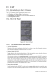
A main menu has been added for PLM to the standard Unigraphics menu. This allows accessing
the features of the integration. It is available within all modules of Unigraphics.
The standard menu structure of the integration is shown in the following diagram.
Chapter 2 - 4
Oracle® Agile Engineering Data Management
MCAD Connector for Unigraphics NX Version 3.9.3.0 - User Manual
Standard Menu Structure
Chapter 2- 5
MCAD Connector for Unigraphics NX Version 3.9.3.0 - User Manual
Load
Model
Load a model of CAX-type "PRT" and CAX-subtype "" (i.e. blank)
Drawings
Load a model of CAX-type "PRT" and CAX-subtype "DP"
Scenarios
Load a model of CAX-type "PRT" and CAX-subtype "SP"
Partfamily Template
Opens the template model of that part family to which the actual work part belongs
provided that the actual work part is an instance of the part family
Reload
Enable reloading of CAD-objects from the PLM vault.
In order to choose the correct object a message window will be displayed before.
For details see below
Load/Reload Components
Provides the following information in a message window about the selected part within an
assembly:
Part name in UG and configurable additional part attributes (s. a. Document-ID, Document name).
Loaded from: Modify flag and identifier if the object is known in the database
Chapter 2 - 6
Oracle® Agile Engineering Data Management
MCAD Connector for Unigraphics NX Version 3.9.3.0 - User Manual
Lists the parts which have been changed in database since they where loaded.
Lists the parts which have been modified in the UG session.
Starts the check for later versions and revisions of loaded parts. Results are displayed in field 3.
If an assembly is selected for reload and this option is activated, all subparts of the assembly are loaded from
the database.
OK = Starts the load or reload procedure for the selected parts.
Cancel = Closes the dialog without loading any part.
Save
Model
Saves a model of CAX-type "PRT". A message window is displayed to check the correct
preconditions and to enable setting of several options.
Workpart only
Saves only the current WorkPart. (Like the comparable CAD - function.)
Drawing
It is possible to save drawings separately to support the master-slave design.
There are 3 modi for saving – "<interactive", "Batch", "Quick".
When a drawing contains parts or assemblies which are unknown to the database, the
user is asked whever he wants to save them in Agile e6 too.
Partfamily Member
Save a model of CAX-type "PRT" and CAX-subtype "SP"
Management of Drawings (Master-Slave Design)
The common saving functions never include an additional query about drawings if contained in the
part file. Drawings must be explicitly saved using the menu Agile > Drawing > Save.
Interactive
A menu is opened showing all drawings belonging to the part. In Quick mode only those
drawings are updated that are already known to Agile e6.
Batch
A menu is opened showing all drawings belonging to the part. In Quick mode only those
drawings are updated that are already known to Agile e6.
Quick
When the modify flag of the part file is set, it is automatically saved in "Quick" mode.
Create
New
A window is opened and a new UG-object (see also "Standard Functions - New Part")
can be created.
New Component
The PLM system is opened and displays a form in edit mode. It is filled with the meta data
of the object.
Chapter 2- 7
MCAD Connector for Unigraphics NX Version 3.9.3.0 - User Manual
Update
Properties
A window is opened to enable selecting the search depth (Part, First Level, All Levels).
(This is obsolete for a part.)
After the property update is done, it is possible to show the result by selecting File >
Properties. Open the Attributes tab. It contains the updated values.
Titleblock
Updates the titleblock of a UG-object of CAX-type "PRT" and CAX-subtype "DP"
Part (Part Mode)
Switch to Local
Sets the saving mode to "local".
Switch to Vault
Sets the saving mode to "vault" (now it is possible to use the file server ).
Remove PLM Info
Removes the database information from the part object. All supplementary information
contained in the file is deleted. The file no longer differs from a normal Unigraphics file.
Reserve
Reserves the part object for the current user.
Remove Reservation
Removes the reservation of the part object.
Set
Enables to modify the CAX-subtype field (T_DOC_DAT.CAX_SUBTYPE) of the actual
UG-object.
Display Metadata
A window is opened to display the Agile e6 metadata of the active object. It is possible
to edit and save the content as a simple text file.
The following information is displayed:
Document ID
Sheet number
Access rights
Owner
Group
Local flag
Part subtype
Assign Document
A Unigraphics model is assigned to an existing Agile e6 document.
In this existing Agile e6 document the field T_DOC_DAT.DOCUMENT_ID, and the field
CAX-type (T_DOC_DAT.CAX_TYPE) has to be filled with the appropriate type of the
CAD-object. The field T_DOC_DAT.CAX_FIL_NAME stays blank.
Chapter 2 - 8
Oracle® Agile Engineering Data Management
MCAD Connector for Unigraphics NX Version 3.9.3.0 - User Manual
Settings
Modifies the CAX-subtype field (T_DOC_DAT.CAX_SUBTYPE) of the current UG-object.
Note
It is a temporary modification until the object or at least its metadata is checked-in.
Part
Removes the content of the CAX-subtype field.
Drawing
Sets the content of the CAX-subtype field to DP if the UG-object is a drawing.
Drawing parts are handled as 2D drawings.
Manufacturing
Sets the content of the CAX-subtype field to MP if the UG-object is intended for CAM.
Scenario
Sets the content of the CAX-subtype field to SP if the UG-object is intended for
simulation.
Auxiliary Part HT
Sets the content of the CAX-subtype field to HT. No item can be created for these
objects.
Auxiliary parts are required for the construction in the CAD system but are not used in the
final manufactured part
This will be done if the UG-object is an auxiliary part if the appropriate item is excluded
when generating a BOM, but its subcomponents are listed in the BOM.
Auxiliary Part LT
Sets the content of the CAX-subtype field to LT. No item can be created for these items.
This will be done if the UG-object is an auxiliary part if the appropriate item is excluded
when generating a BOM. Its subcomponents are NOT listed in the BOM.
Standard Part
Sets the content of the CAX-subtype field to NT. These objects are managed in separate
directories.
Here is an example:
Chapter 2- 9
MCAD Connector for Unigraphics NX Version 3.9.3.0 - User Manual
Family Table
Save > Partfamily Members
Generates / configures a part which is a real instance of a part family, e. g.
Normparts. In Unigraphics this is called a family member.
Load > Partfamily Template
Opens the tabular template of that part family to which the work part belongs.
(i.e., an instance of the part family).
Assembly (Assembly Mode)
Switch to Local
Sets the saving mode to "local"
Switch to Vault
Sets the saving mode to "vault" (now it is possible to use the file server )
Remove PLM Info
Removes the database information from the part object. All supplementary information
contained in the file is deleted. The file no longer differs from a normal Unigraphics
file.
If the removed information is needed again, it can only be loaded from PLM again.
It is recommended to use the Save_As function instead.
Reserve
Reserves the part object(s) for the current user. A window is opened to select the
objects to be reserved.
Remove Reservation
Removes the reservation of the part object. A window is opened to select the objects
to remove the reservation.
Chapter 2 - 10
Oracle® Agile Engineering Data Management
MCAD Connector for Unigraphics NX Version 3.9.3.0 - User Manual
Display Metadata
A window is opened to enter the document-ID of the desired component object. The
name of the part can be registered manually or by clicking the desired part. If the entry
is not clear, an additional window is opened to choose the respective part.
After clicking OK, another window is opened, displaying the following information:
Document ID
identifier in Agile e6
Sheet number
Access rights
Access rights based on
Agile e6 conventions
<d>:delete = full access
<w>: write = write access
<r>:read = read access
Owner
Name of the object
owner
Group
Group membership of the
owner
Local flag
If set then the object is
saved only locally
Part subtype
It is possible to edit and save the content as a simple text file.
Drawing (Drawing Mode)
Update Titleblock
Updates the titleblock of a UG-object of CAX-type "PRT" and CAX-subtype "DP".
Delete Frame
Removes a drawing frame from the display.
Change Frame
Changes the drawing frame. You can choose between a standard frame or an alternate
format if it is installed.
Change Size
Changes the size of the drawing frame. A list of the available formats is displayed.
Add History
Inserts a history entry into the database (e.g. an editorial note). When reloading the
drawing frames an annotation is automatically placed in the assigned fields.
When choosing one of these options, the program tries to adapt the content.
Chapter 2- 11
MCAD Connector for Unigraphics NX Version 3.9.3.0 - User Manual
Partlist
Special Functions for Partlist on Drawing
Refresh Attributes and Callouts => Updates Callouts and Component Attributes with
PLM-BOM-Values
Refresh Attributes only => Updates Component Attributes with PLM-BOM-Values
Rebuild completely from BOM => Delete all Attributes and create new values
Link Callouts to BOM Pos => Link existing Callouts with PLM-Pos.Number
Item (Item Mode)
Create / Update
Generates an item for the selected object or updates the existing item metadata set.
The Agile e6 item form is opened in which the information about the item can be
specified.
Assign
Enables to assign a UG object which is already known in Agile e6 (i.e. it is described
by a document) to an existing item metadata set.
BOM
Item forms are brought up at first for items that are yet unknown to Agile e6. Once it
has been made known to Agile e6 by filling out and saving the form, a parts list can be
generated. This is organized as an item structure table.
Interactive = generates parts list entries through a dialog
Batch = generates parts list entries in the background
Tools and Service Functions
Start PLM
Starts the Agile e6 client from Unigraphics.
Stop PLM
Stops the Agile e6 client from Unigraphics.
Chapter 2 - 12
Oracle® Agile Engineering Data Management
MCAD Connector for Unigraphics NX Version 3.9.3.0 - User Manual
Debug
Starts the testing mode.
A trace file is created in the path displayed in the message window. It allows a detailed
tracking of errors. The file content can be displayed in a text editor.
Batch = Switches on in the background
Interactive = Switches on in dialog mode. From this moment all functions of the integration
are switched to the interactive mode.
Close = Switches off
Info List
Shows the Agile e6 status list in the information window. Displays a table listing the
following information:
Lv:
Number of levels in the assembly tree
Partname:
Object name
State:
Independent user object (USER) or registered in Agile e6
Res:
Reserved by. (user ID, 000 = not reserved)
Owner:
Object owner
Group:
User group
Acc:
Access rights for user according to those assigned in Agile e6:
<d>: delete = full access
<w>: write = write access
<r>: read = read access
Con
Object in concurrent conflict:
no
yes
Modif:
Object modified. Syntax: no/0 or yes/1 in Agile e6 / in UG
0=no
1=yes
Loc:
Object saved without file server:
no
yes
Display Buffer
Shows the content of the message buffer in a separate information window.
Only the recent 100 lines are displayed. The display is in reverse order, thus the first line is
the most recent message.
Clear Buffer
Deletes the content of the message buffer.
Chapter 2- 13
MCAD Connector for Unigraphics NX Version 3.9.3.0 - User Manual
Initial Load Parts
Enables to perform an initial load process in order to fill the vault according to the customerspecific selection of the files in the local "Load" directory. Settings in the file EcuMigrate.ini
control this. The adaptation of the ini-file results from detailed specifications made by the
customer.
Call TCL
Call the TCL script EcuTclMenu.tcl. It defines custom features (e.g. for data initialization).
Chapter 2 - 14
Oracle® Agile Engineering Data Management
MCAD Connector for Unigraphics NX Version 3.9.3.0 - User Manual
Chapter 3
Data Model
The integration depicts the two Unigraphics object types (Part and Drawing) in the Agile e6 data
model, including their relationship to another. The following illustrations depicts the principle forms
of a part-drawing relationship in various designs ( MASTER-SLAVE; MASTER-MODEL ) in
combination with Agile e6.
MASTER-SLAVE Design
à
Drawing is contained in the part document.
à
No separate access rights for the model and its drawing.
à
Drawing is revisioned with the model.
à
A slave (drawing) does not have its own test sequence.
à
Status changes in the model automatically result in status changes in the drawing.
Chapter 3- 15
MCAD Connector for Unigraphics NX Version 3.9.3.0 - User Manual
MASTER MODEL Design
à
Drawing is not in the part document.
à
Model is revisioned independently from the drawing.
à
Separate access rights for the model and its drawing.
Chapter 3 - 16
Oracle® Agile Engineering Data Management
MCAD Connector for Unigraphics NX Version 3.9.3.0 - User Manual
ASSEMBLY-COMPONENT Relationship
The following illustration represents an assembly-component relationship in interaction with
Agile e6:
An internal object list is maintained in every Unigraphics session. The coherence between a
Unigraphics "Part" type object and a corresponding Agile e6 attribute list is ensured by an object
pointer.
A generic data record in the Unigraphics part file is always written before this attribute list is saved.
When such a part is loaded from Agile e6, the generic data record is nonrelevant. When it is loaded
from the user area, however, the generic data is used to determine if the part name or the
corresponding Agile e6 document set has changed. When no irregularity is determined, an entry is
made in the internal object list, otherwise the generic data record is deleted.
"PRT" type objects can be divided into three classes with an entry in the field "cax_subtype":
NT
Object is a norm part. It is maintained in a separate directory and does not change its file name. The
parameter for the use of the file server is not evaluated.
Chapter 3- 17
MCAD Connector for Unigraphics NX Version 3.9.3.0 - User Manual
HT
Object is a help part. No item can be created for this object through the integration. It is not considered
in the parts list. When the object contains components, in the generation of the parts list they are
assigned directly to the first subordinate "non"-help part (see illustration below).
(i.e. "empty") Object is a common part.
Chapter 3 - 18
Oracle® Agile Engineering Data Management
MCAD Connector for Unigraphics NX Version 3.9.3.0 - User Manual
Chapter 4
Basic Functions
General Information
The integration offers the possibility to create generic data records in Agile e6 for part files from
Unigraphics models. This allocation is maintained even when the part files are saved locally and
loaded again from their local directory. This ensures full support for 3D standard part libraries. It
also enables the use of the Unigraphics Navigation Tool for temporary opening and closing of parts
and assemblies.
The added parameter transfer feature enables saving of parts in batch mode even when the part
data is unknown in Agile e6. The Save..., Quick..., or Batch options attempt to create the object
using the values defined in the parameter files. If this is impossible, a second attempt in interactive
mode is offered automatically.
Generate Influenced Parts List
Unigraphics objects can be declared as help parts by an entry in the field "CAX_SUBTYPE". In this
case no item will be created for these parts through the integration. When such objects are
integrated in an assembly, they are ignored while the part list will be generated. It is possible to
influence the generation of a part list using the component name ("ComponentNames"). Only
components with the same name can be assembled under a common parts list.
Usage of Standard Objects
A predefined part file can be used when activating the "New.. " option. This can contain customized
settings. The names of the standard objects are defined in the file ecu_ini.com by the environment
variables:
ECU_blank_part
Blank part metric
ECU_blank_drw
Blank drawing metric
ECU_blank_part_in
Blank part inch
ECU_blank_drw_in
Blank drawing inch
This has the advantage of providing a uniform basis in a construction environment which is the most
important prerequisite for enforcing construction guidelines.
Create New Part
1.
To create a new part click the "New" button.
The Create window is opened.
Chapter 4- 19
MCAD Connector for Unigraphics NX Version 3.9.3.0 - User Manual
y
y
y
y
Note
Part = Generates a part with Agile e6.
Drawing = Generates a drawing with Agile e6 using the master model.
Manufacturing = Generates a manufacturing object with Agile e6 using the master model.
USER = Generates a part in the user directory. This is the original UG function.
The Option “Relate to a Workpart” works for Drawings and creates a Master Model
Drawing (with CAD Structure)
2.
The first three options open an Agile e6 form.
3.
Enter document number and name of the object.
4.
Save the form.
Note
The default base unit is mm. The default seed part is blank.prt.
Note
The CAD manager can change or add this default settings.
Chapter 4 - 20
Oracle® Agile Engineering Data Management
MCAD Connector for Unigraphics NX Version 3.9.3.0 - User Manual
Open Part
Note
1.
If you want to load an existing part, you can either do it directly from Unigraphics or reload
parts and assemblies from database.
Click the Open button in Unigraphics.
The Open mask is opened.
Toggles the load command between ‘Database’ and ‘Directory’.
Directory = Enables the default load userexit of UG by selecting a part file in a directory. Whenever this
option is used the options from 2 to 6 are disabled.
Quickload reduces load time from the database. If this option fails, some errors can occur in the
database or in single datasets. In this case, disable this option and load again.
When active, the DFM database Quickload Functions and Stored Procedure have to be configured.
When active, the UG load option is modified and no component, but only the top assembly is opened.
When the checkbox 4 is activated the subparts nethertheless are checked out from vault to a local disc.
But they are not loaded into Unigraphics in order to consume fewer memory.
When the checkbox 4 is not activated no subpart will be checked out from vault.
When active, the selected assembly and all of its subparts will be copied from vault to local disc. From
here they can be loaded into the UG session.
Checks the local timestamps. Only the files that have not been stored in the database are copied from
the vault to the local disc. This reduces network traffic and increases load speed.
When Quickload is not selected, this option is active. It updates the attributes configured in the file
…\tcl\ecu.ini in the session [EcuGetDocumentInfo] as values to be returned. This allows to modify the
UG part file during a work session.
2.
To start the load procedure click OK.
Chapter 4- 21
MCAD Connector for Unigraphics NX Version 3.9.3.0 - User Manual
3.
To close the mask without loading click Cancel.
Note
Additional settings can be customized using the "LOAD OPTIONS" like described in the
Unigraphics documentation.
Note
Alternatively, the load option can also be started from the menu Agile > Load.
Save Part
1.
Select File > Save as in the Cad system,
The Save in PDM window is opened.
Chapter 4 - 22
Oracle® Agile Engineering Data Management
MCAD Connector for Unigraphics NX Version 3.9.3.0 - User Manual
Name of the part in Unigraphics. (USR) describes a new part file not currently known inside the database.
(EDB) marks database known partfiles. Additional marks have the following meanings:
m = Part is modified in Unigraphics session
L = Part is recognized to be modified on disk, or was in an earlier UG-session since the last Save or Load
command.
M = Part is a member part In UG this is in read-only.
r = Part is in database in read-only and may not be modified from the current user.
C = Part has been modified in database since it was loaded into the current UG session.
RES = Part is reserved in database, the user name, who has reserved is, and the reservation date are
displayed.
Checks the access and reservation information in the database for all parts marked as modified. The result is
listed in a frame using the marks described under 1. This ensures the right access to the required database
objects.
See description for 2. It also includes not modified parts.
Removes the reservation in database of the selected parts.
Sets the reservation in database for the selected parts.
Displays bigger assemblies and assembly cloning in a tree-like structure for a better work when performing
Save As”. It disables checkbox 9 and is the default for “Save As”.
Displays in a unified list. This disables checkbox 8 and is the default for “Save”.
Defines the tree expansion for the depth (one or all levels) of the current top assembly.
Filters the modified parts in a list when selected; shows all parts when not selected.
Selects all parts and subparts of the top assembly for “Save” or “Save As”.
Selects modified parts and subparts of the top assembly for “Save” or “Save As”, where the user has write
access in the database.
Saves all selected parts in interactive mode. Each part file prompts for input using a database mask.
Saves all selected parts in background without showing any prompts.
Saves all selected parts to disk (users work area) only. The parts will be marked as modified for later save
into database.
Chapter 4- 23
MCAD Connector for Unigraphics NX Version 3.9.3.0 - User Manual
Recommended only for save of minor changes. This updates only the part file and the structure in database.
No document attributes are changed. Should only be used when all parts within the assembly are created
and saved with the same unique UG-version and all are already known in the database. Not active in
standard delivery!
Enables or disables saving of external part references into the database structure, such as WAVE-links or
interpart expressions. This may cause circle references if sub parts reference to upper parts.
It is possible that database, workflow, and release management may not support the storage of the
references.!
Removes the reservation after the check-in of the part file. To work properly the appropriate customization of
the concrete situation has to be done in EcuPostCheckin.tcl by a customizer.
OK = Starts the save or save_as procedure for the selected parts.
Cancel = Closes the mask without saving any part.
Add Component
1.
Select Assemblies > Components > Add existing.
A window is opened where you can select
à
User = Adds a part to the assembly structure from the user area or from the current session
(the original Unigraphics function ).
à
PLM = Adds a part to the assembly structure with Agile e6
2.
Select "PLM" and click OK.
The document mask in the PLM system is opened.
Assign an Object to an Existing Agile Document
1.
To assign a Unigraphics model to an existing Agile e6 document select Agile > Part > Assign
Document.
2.
In the Agile e6 document the document number (T_DOC_DAT.DOCUMENT_ID) field has to be
already filled.
3.
The CAX type (T_DOC_DAT.CAX_TYPE) field is filled with the respective type of the CADobject.
4.
The CAX name (T_DOC_DAT.CAX_FIL_NAME) field remains blank.
Chapter 4 - 24
Oracle® Agile Engineering Data Management
MCAD Connector for Unigraphics NX Version 3.9.3.0 - User Manual
Chapter 5
Appendix
Part Family
Only minimal extensions should be added when using the ECU integration. Therefore, the usage of
Part Family is quite similar to UG itself. For more details (e.g. how to define parameters) please
refer the appropriate UG documentation.
Note
Only the necessary special extensions regarding the ECU integration are described here.
Create a Part Family Template
1.
File > New > PLM-part (mm).
Complete the mandatory fields in the new PLM document and save it. A new UG part object is
opened with the document-ID as name.
2.
Tools > Part Families…
Creates the UG model as template of the new part family. The Part Families window is
displayed.
3.
Add the names of the needed parameter columns and create an Excel spreadsheet by clicking
the "Create" button.
4.
Fill in the displayed Excel spreadsheet.
Note
5.
The content of the fields "DB_PART_NO“ and "OS_PART_NAME“ have to be identical for
each family member. The content of "OS_PART_NAME" for the template has to be
unique.
Click Part Family > Save Family to close the spreadsheet.
The spreadsheet is embedded into the UG object file of the template. It can be edited later.
6.
To close the Part Families window click OK.
7.
To save the UG file select File > Save in PLM vault.
Create Part Family Members
1.
Click Agile > Save > PartFamily Members.
The Select Parts window is opened displaying the members that were defined in the Excel
spreadsheet.
2.
Select the member(s) to be saved and click OK.
A message is displayed.
Chapter 5- 25
MCAD Connector for Unigraphics NX Version 3.9.3.0 - User Manual
3.
Click OK.
The Aglile e6 client is opened displaying 3D Model form in edit mode. The Name field contains
the content of the Excel spreadsheet field „OS_PART_NAME“ for this object. The document
number is filled out deriving from the configuration made in the appropriate .par file. These
entries can be edited.
4.
To finish the edit mode click the save button.
Note
The next 3D Model form is opened in edit-mode for the next member. Perform the same
steps as described before.
Note
When this is performed for all selected members, the respective UG object files are
checked-in and the structure between the template and its members is created in PLM.
Chapter 5 - 26
Oracle® Agile Engineering Data Management
MCAD Connector for Unigraphics NX Version 3.9.3.0 - User Manual
Add and Edit Part Family Members
1.
To load the family table templates from Agile e6 select Agile > Load > Model.
2.
Select Tools > Part Families.
The Part Families window is opened.
Chapter 5- 27
MCAD Connector for Unigraphics NX Version 3.9.3.0 - User Manual
3.
To open the Excel spreadsheet click Edit.
4.
Edit the value(s) for an existing, or add to the displayed Excel spreadsheet the lines with the
values for family members.
5.
To close the displayed spreadsheet select PartFamily > Save Family.
6.
Select Agile > Save > Part Family Members.
An information window is opened displaying all known member. Select the new member(s) to
be saved.
Note
7.
Members which are marked with "(EDB)" are already found in Agile e6. If there
is an edited member, mark it too.
Click OK.
A message is displayed.
8.
Click OK.
The Aglile e6 client is opened displaying 3D Model form in edit mode. The Name field contains
Chapter 5 - 28
Oracle® Agile Engineering Data Management
MCAD Connector for Unigraphics NX Version 3.9.3.0 - User Manual
the content of the Excel spreadsheet field „OS_PART_NAME“ for this object. The document
number is filled out deriving from the configuration made in the appropriate .par file. These
entries can be edited.
9.
To finish the edit mode click the save button.
A warning is displayed.
10. Click OK.
Note
The next 3D Model form is opened in edit-mode for the next member. Perform
the same steps as described before.
Note
When this is performed for all selected members, the respective UG object files
are checked-in and the structure between the template and its members is
created in PLM.
11. The updated members are available now. Close the UG template object.
Load Part Family Members
1.
Select Agile > Load > Model.
2.
To load the Familytable Member from Agile e6 select the document number or name.
Note
The checked out UG object file is read-only.
Chapter 5- 29
MCAD Connector for Unigraphics NX Version 3.9.3.0 - User Manual
Chapter 5 - 30
Oracle® Agile Engineering Data Management