1
PCAN-ExpressCard
CAN Interface for the
ExpressCard Slot
User Manual
Document version 2.3.0 (2015-06-15)
PCAN-ExpressCard – User Manual
Products taken into account
Product Name
Model
Part Number
PCAN-ExpressCard Single
Channel
One CAN channel
IPEH-003000
PCAN-ExpressCard Dual
Channel
Two CAN channels
IPEH-003001
PCAN-ExpressCard Single
One CAN channel, galvanic
Channel galvanically decoupled isolation for CAN connection
IPEH-003002
PCAN-ExpressCard Dual
Two CAN channels, galvanic
IPEH-003003
Channel galvanically decoupled isolation for CAN connections
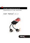
The cover picture shows the product PCAN-ExpressCard Dual Channel. Other product
models have an identical form factor but vary in the number of CAN connectors
according to the model.
CANopen® and CiA® are registered community trade marks of CAN in Automation
e.V.
All other product names mentioned in this document may be the trademarks or
registered trademarks of their respective companies. They are not explicitly marked
by “™” and “®”.
Copyright © 2015 PEAK-System Technik GmbH
Duplication (copying, printing, or other forms) and the electronic distribution of this
document is only allowed with explicit permission of PEAK-System Technik GmbH.
PEAK-System Technik GmbH reserves the right to change technical data without
prior announcement. The general business conditions and the regulations of the
license agreement apply. All rights are reserved.
PEAK-System Technik GmbH
Otto-Roehm-Strasse 69
64293 Darmstadt
Germany
Phone: +49 (0)6151 8173-20
Fax:
+49 (0)6151 8173-29
www.peak-system.com
[email protected]
Document version 2.3.0 (2015-06-15)
2
PCAN-ExpressCard – User Manual
Contents
1
1.1
1.2
1.3
Introduction
5
Properties at a Glance
Prerequisites for Operation
Scope of Supply
5
6
6
2
Installing the Software and the Card
7
3
Connecting the CAN Bus
9
3.1
3.2
D-Sub Connector
Supplying External Devices via the CAN
Connector
3.3 Cabling
3.3.1
Termination
3.3.2
Example of a Connection
3.3.3
Maximum Bus Length
9
10
10
10
11
4
12
4.1
4.2
5
Operation
Status LED
Removing the Adapter
9
12
12
Software and API
13
5.1 Monitor Software PCAN-View
5.1.1
Receive/Transmit Tab
5.1.2
Trace Tab
5.1.3
PCAN-ExpressCard Tab
5.1.4
Status Bar
5.2 Linking Own Programs with PCAN-Basic
5.2.1
Features of PCAN-Basic
5.2.2
Principle Description of the API
5.2.3
Notes about the License
3
13
16
18
19
20
21
22
23
24
PCAN-ExpressCard – User Manual
6
Technical Specifications
25
Appendix A
CE Certificate
27
Appendix B
Dimension Drawing
28
Appendix C
Quick Reference
29
4
PCAN-ExpressCard – User Manual
1
Introduction
The PCAN-ExpressCard provides a connection between a CAN bus
and a laptop or desktop PC with an ExpressCard slot. The card is
available in single and dual-channel versions. There are also galvanically separated versions which guarantee galvanic separation
up to a maximum of 300 Volts between the PC and CAN sides.
Device drivers and programming interfaces exist for different operating systems, so programs can easily access a connected CAN bus.
Tip: At the end of this manual (Appendix C) you can find a
Quick Reference with brief information about the installation
and operation of the PCAN-ExpressCard.
1.1
Properties at a Glance
Card for ExpressCard slot
Form factor ExpressCard/54
1 or 2 High-speed CAN channels (ISO 11898-2)
Compliant with CAN specifications 2.0A (11-bit ID)
and 2.0B (29-bit ID)
Bit rates from 5 kbit/s up to 1 Mbit/s
CAN bus connection via D-Sub, 9-pin (in accordance to
CiA® 102)
NXP SJA1000 CAN controller, 16 MHz clock frequency
NXP PCA82C251 CAN transceiver
Galvanic isolation on the CAN connection up to 300 V (only
galvanically decoupled models), separate for each CAN channel
5
PCAN-ExpressCard – User Manual
Software option to switch a 5-Volt supply to the CAN
connection, e.g. for external bus converter
Operating temperature range from 0 to 70 °C (32 to 158 °F)
Note: This manual describes the use of the PCAN-ExpressCard
with Windows. You can find device drivers for Linux and the
corresponding application information on the provided DVD in
the directory branch Develop and on our website under
www.peak-system.com/linux.
1.2
Prerequisites for Operation
ExpressCard slot in the computer, type ExpressCard/54
Operating system Windows 8.1, 7, Vista (32/64-bit)
or Linux (32/64-bit)
1.3
Scope of Supply
PCAN-ExpressCard CAN interface
Device drivers for Windows 8.1, 7, Vista (32/64-bit)
and Linux (32/64-bit)
PCAN-View CAN monitor for Windows 8.1, 7, Vista (32/64-bit)
PCAN-Basic programming interface consisting of an interface
DLL, examples, and header files for all common programming
languages
Manual in PDF format
6
PCAN-ExpressCard – User Manual
2
Installing the Software and
the Card
This chapter covers the software setup for the PCAN-ExpressCard
under Windows and the installation in the computer.
Setup the driver before connecting the PCAN-ExpressCard for the
first time.
Do the following to install the driver:
1.
Insert the supplied DVD into the appropriate drive of the
computer. Usually a navigation program appears a few
moments later. If not, start the file Intro.exe from the root
directory of the DVD.
2.
In the main menu, select Drivers, and then click on
Install now.
3.
Confirm the message of the User Account Control regarding
the "Installer Database of PEAK Drivers".
The setup program for the driver is started.
4.
Follow the instructions of the program.
7
PCAN-ExpressCard – User Manual
Do the following to connect the PCAN-ExpressCard to the
computer and complete the initialization:
1.
Insert the PCAN-ExpressCard into an ExpressCard slot of
your computer. The computer can remain powered on.
Windows notifies that new hardware has been detected. The
drivers are found and installed by Windows automatically.
After the initialization process for the driver for the CAN interface is
finished successfully an LED is on for each CAN connection of the
PCAN-ExpressCard. Furthermore, you can find the entry “PCANExpressCard” in the branch “CAN-Hardware” of the Windows
Device Manager.
8
PCAN-ExpressCard – User Manual
3
3.1
Connecting the CAN Bus
D-Sub Connector
A High-speed CAN bus (ISO 11898-2) is connected to the 9-pin DSub connector. The pin assignment corresponds to the specification
CiA® 102.
Figure 1: Pin assignment High-speed CAN
3.2
Supplying External Devices via the CAN
Connector
Optionally a 5-Volt supply can be switched with the provided
Windows software PCAN-View onto pin 1 of a D-Sub CAN
connector (for the Dual Channel model simultaneously for both
CAN connectors). Thus devices with low power consumption (e.g.
bus converters) can be directly supplied via the CAN connector.
When using this option the 5-Volt supply is directly connected to the
power supply of the computer and is not fused separately. The
galvanically decoupled models of the card have an interconnected
DC/DC converter. Therefore the current output is limited to 50 mA.
You find further information about the use of this option in PCANView in section 5.1.3 on page 19.
9
PCAN-ExpressCard – User Manual
Attention! Risk of short circuit! If the option described in this
section is activated, you may only connect or disconnect CAN
cables or peripheral systems (e.g. bus converters) to or from
the PCAN-ExpressCard while it is de-energized (the card is not
connected to the computer). Consider that some computers still
supply the ExpressCard slot with power even when they are
turned off (standby operation).
3.3
3.3.1
Cabling
Termination
A High-speed CAN bus (ISO 11898-2) must be terminated on both
ends with 120 Ohms. Otherwise, there are interfering signal
reflections and the transceivers of the connected CAN nodes (CAN
interface, control device) will not work.
The PCAN-ExpressCard does not have an internal termination. Use
the adapter on a terminated CAN bus.
3.3.2
Example of a Connection
Figure 2: Simple CAN connection
In this example, the PCAN-ExpressCard is connected with a control
unit by a cable that is terminated at both ends.
10
PCAN-ExpressCard – User Manual
3.3.3
Maximum Bus Length
High-Speed-CAN networks may have bit rates of up to 1 Mbit/s. The
maximum bus length depends primarily on the bit rate.
The following table shows the maximum possible CAN bus length
at different bit rates:
Bit rate
Bus length
1 Mbit/s
40 m
500 kbit/s
110 m
250 kbit/s
240 m
125 kbit/s
500 m
50 kbit/s
1.3 km
20 kbit/s
3.3 km
10 kbit/s
6.6 km
5 kbit/s
13.0 km
The listed values have been calculated on the basis of an idealized
system and can differ from reality.
11
PCAN-ExpressCard – User Manual
4
4.1
Operation
Status LED
The PCAN-ExpressCard has a status LED for each existing CAN
channel which may be in one of the following conditions:
Status LED
Meaning
On
There's a connection to a driver of the operating
system.
Slow blinking
A software application is connected to the CAN
channel.
Quick blinking
Data is transmitted via the connected CAN bus.
4.2
Removing the Adapter
Under Windows the icon for removing hardware safely is not used
with the PCAN-ExpressCard. You may remove the card from the
computer without any preparation under Windows.
12
PCAN-ExpressCard – User Manual
5
Software and API
This chapter covers the provided software PCAN-View and the
programming interface PCAN-Basic.
5.1
Monitor Software PCAN-View
PCAN-View is simple Windows software for viewing, transmitting,
and logging CAN- and CAN FD messages.
Note: This chapter describes the use of PCAN-View with a CAN
adapter.
Figure 3: PCAN-View for Windows
13
PCAN-ExpressCard – User Manual
Do the following to start and initialize PCAN-View:
1.
Open the Windows Start menu or the Windows Start page
and select PCAN-View.
The dialog box for selecting the hardware and for setting
the parameters appears.
Figure 4: Selection of the specific hardware and parameters
2.
From the list Available PCAN hardware, select the desired
interface to be used.
3.
Select the bit rate that is used by all nodes on the CAN bus
from the drop-down list Bit rate. Use the button to the right
of the drop-down list to create User-defined bit rates.
4.
Under Filter settings you can limit the range of CAN IDs to
be received, either for standard frames (11-bit IDs) or for
extended frames (29-bit IDs).
14
PCAN-ExpressCard – User Manual
5.
Activate the Listen-only mode if you do not actively
participate in the CAN traffic and just want to observe. This
also avoids an unintended disruption of an unknown CAN
environment (e.g. due to different bit rates).
6.
Finally, confirm the settings in the dialog box with OK. The
main window of PCAN-View appears (see Figure 5).
15
PCAN-ExpressCard – User Manual
5.1.1
Receive/Transmit Tab
Figure 5: Receive/Transmit tab
The Receive/Transmit tab is the main element of PCAN-View. It
contains two lists, one for received messages and one for the
transmit messages. Representation of CAN data is in hexadecimal
format.
Do the following to transmit a CAN message with PCAN-View:
1.
Select the menu command Transmit > New Message
(alternatively
or Ins).
The dialog box New Transmit Message is shown.
16
PCAN-ExpressCard – User Manual
Figure 6: Dialog box new transmit message
2.
Enter the ID and the data for the new CAN message.
3.
The field Cycle Time indicates if the message shall be
transmitted manually or periodically. If you want to transmit
the message periodically, you must enter a value greater
than 0. For a manual-only transmission enter 0.
4.
Confirm the entries with OK.
The created transmit message appears on the
Receive/Transmit tab.
5.
You trigger selected transmit messages manually with the
menu command Transmit > Send (alternatively Space bar).
The manual transmission for CAN messages being
transmitted periodically is carried out additionally.
Tip: Using the menu command File > Save the current transmit
messages can be saved to a list and loaded for reuse later on.
17
PCAN-ExpressCard – User Manual
5.1.2
Trace Tab
Figure 7: Trace tab
On the Trace tab the data tracer of PCAN-View is used for logging
the communication on a CAN bus. During this process the CAN
messages are cached in the working memory of the PC. Afterwards
they can be saved to a file.
The tracer can be configured to run in linear or in ring buffer mode.
In linear buffer mode the logging is stopped as soon as the buffer is
filled completely. In ring buffer mode the oldest messages are
overwritten by incoming ones.
18
PCAN-ExpressCard – User Manual
5.1.3
PCAN-ExpressCard Tab
Figure 8: PCAN-ExpressCard tab
On the PCAN-ExpressCard tab the 5-Volts supply on pin 1 of the
D-Sub CAN connector is enabled or disabled. For the Dual Channel
model the setting is valid for both CAN connectors simultaneously.
You find information about technical details in section 3.2
on page 9.
To toggle the setting press the button Enable / Disable.
Attention! Risk of short circuit! If the option described in this
section is activated, you may only connect or disconnect CAN
cables or peripheral systems (e.g. bus converters) to or from
the PCAN-ExpressCard while it is de-energized (the card is not
connected to the computer). Consider that some computers still
supply the ExpressCard slot with power even when they are
turned off (standby operation).
19
PCAN-ExpressCard – User Manual
5.1.4
Status Bar
Figure 9: Example of the status bar
The status bar shows information about the current CAN
connection, about error counters (Overruns, QXmtFull), and shows
error messages.
You can find further information about the use of PCAN-View in the
help which you can invoke in the program via the Help menu or
with the F1 key.
20
PCAN-ExpressCard – User Manual
5.2
Linking Own Programs with PCAN-Basic
Figure 10: PCAN-Basic
On the provided DVD you can find files of the programming
interface PCAN-Basic in the directory branch Develop. This API
provides basic functions for linking own programs to CAN- and CAN
FD interfaces by PEAK-System and can be used for the following
operating systems:
Windows 8.1, 7, Vista (32/64-bit)
Windows CE 6.x (x86/ARMv4)
Linux (32/64-bit)
The API is designed for cross-platform use. Therefore software
projects can easily ported between platforms with low efforts. For
all common programming languages examples are available.
Beginning with version 4, PCAN-Basic supports the new CAN FD
standard (CAN with Flexible Data Rate) which is primarily
characterized by higher bandwidth for data transfer.
21
PCAN-ExpressCard – User Manual
5.2.1
Features of PCAN-Basic
API for developing applications with CAN and CAN FD
connection
Access to the CAN channels of a PCAN-Gateway via the new
PCAN-LAN device type
Supports the operating systems Windows 8.1, 7, Vista (32/64bit), Windows CE 6.x, and Linux (32/64-bit)
Multiple PEAK-System applications and your own can be
operated on a physical channel at the same time
Use of a single DLL for all supported hardware types
Use of up to 16 channels for each hardware unit (depending on
the PEAK CAN interface used)
Simple switching between channels of a PEAK CAN interface
Driver-internal buffer for 32,768 messages per CAN channel
Precision of time stamps on received messages up to 1 μs
(depending on the PEAK CAN interface used)
Supports PEAK-System‘s trace formats version 1.1 and 2.0 (for
CAN FD applications)
Access to specific hardware parameters, such as listen-only
mode
Notification of the application through Windows events when a
message is received
Extended system for debugging operations
Multilingual debugging output
Output language depends on operating system
Debugging information can be defined individually
22
PCAN-ExpressCard – User Manual
An overview of the API functions is located in the header files. You
can find detailed information about the PCAN-Basic API on the
provided DVD in the text and help files (file name extensions .txt
and .chm).
5.2.2
Principle Description of the API
The PCAN-Basic API is the interface between the user application
and device driver. In Windows operating systems this is a DLL
(Dynamic Link Library).
The sequence of accessing the CAN interface is divided into three
phases:
1. Initialization
2. Interaction
3. Completion
Initialization
A channel must be initialized before using it. This is done by the
simple call of the function CAN_Initialize for CAN and
CAN_InitializeFD for CAN-FD. Depending on the type of the CAN
hardware, up to 16 CAN channels can be opened at the same time.
After a successful initialization the CAN channel is ready for
communication with the CAN hardware and the CAN bus. No
further configuration steps are required.
Interaction
For receiving and transmitting messages the functions CAN_Read and
CAN_Write as well as CAN_ReadFD and CAN_WriteFD are available.
Additional settings can be made, e.g. setting up message filters to
confine to specific CAN IDs or setting the CAN controller to listenonly mode.
23
PCAN-ExpressCard – User Manual
When receiving CAN messages, events are used for an automatic
notification of an application (client). This offers the following
advantages:
The application no longer needs to check for received messages
periodically (no polling).
The response time at reception is reduced.
Completion
To end the communication the function CAN_Uninitialize is called in
order to release the reserved resources for the CAN channel, among
others. In addition the CAN channel is marked as "Free" and is
available to other applications.
5.2.3
Notes about the License
Device drivers, the interface DLL, and further files needed for linking
are property of the PEAK-System Technik GmbH and may be used
only in connection with a hardware component purchased from
PEAK-System or one of its partners. If a CAN hardware component
of third-party suppliers should be compatible to one of PEAKSystem, then you are not allowed to use or to pass on the driver
software of PEAK-System.
If a third-party supplier develops software based on the PCAN-Basic
and problems occur during the use of this software, consult the
software provider.
24
PCAN-ExpressCard – User Manual
6
Technical Specifications
Connectors
Computer
ExpressCard slot, type ExpressCard/54
CAN
D-Sub (m), 9 pins
Pin assignment according to specification CiA® 102
CAN
Specification
ISO 11898-2, High-speed CAN
2.0A (standard format) and 2.0B (extended format)
Bit rates
5 kbit/s - 1 Mbit/s
Controller
NXP SJA1000
Transceiver
NXP PCA82C251
Galvanic isolation
PCAN-ExpressCard: none
PCAN-ExpressCard opto: Galvanic isolation up to
300 V (separate for each CAN channel)
Supplying external
devices
PCAN-ExpressCard: D-Sub pin 1; 5 V, max. 100 mA
PCAN-ExpressCard opto: D-Sub pin 1; 5 V, max. 50 mA
Switched off at delivery
Termination
none
Power supply
Current consumption
(max.)
Product model
Single Channel:
Dual Channel:
Single Channel opto:
Dual Channel opto:
25
on 1.5-V pin
on 3.3-V pin
142 mA
142 mA
142 mA
142 mA
245 mA
296 mA
273 mA
335 mA
PCAN-ExpressCard – User Manual
Measures
Size (without cables)
130 x 54 x 10 mm (L x W x D)
See also dimension drawing in Appendix B on page 28
Weight
Product model
Single Channel:
Dual Channel:
Single Channel opto:
Dual Channel opto:
60 g
80 g
60 g
80 g
Environment
Operating temperature
0 - 70 °C (32 - 158 °F)
Temperature for storage
and transport
-30 - 100 °C (-22 - 212 °F)
Relative humidity
15 - 90 %, not condensing
EMC
EN 55024:2011-09
EN 55022:2011-12
EC directive 2004/108/EG
Ingress protection
(IEC 60529)
IP30
26
PCAN-ExpressCard – User Manual
Appendix A
CE Certificate
27
PCAN-ExpressCard – User Manual
Appendix B
Dimension Drawing
Figure 11: Side view and top view of the PCAN-ExpressCard
The figure does not show the actual size of the product.
28
PCAN-ExpressCard – User Manual
Appendix C
Quick Reference
Software/Hardware Installation under Windows
Before connecting the PCAN-ExpressCard to the computer set up
the corresponding software package from the supplied DVD (with
administrator privileges). Afterwards insert the card into a
ExpressCard slot of the computer. The card is recognized by
Windows and the driver is initialized. After the installation process
is finished successfully, an LED is on for each CAN channel of the
card.
Getting Started under Windows
Run the CAN monitor PCAN-View from the Windows Start menu as
a sample application for accessing the PCAN-ExpressCard. For
initialization of the card select the CAN connection and the CAN bit
rate.
Status LED
Meaning
On
There's a connection to a driver of the operating system.
Slow blinking
A software application is connected to the CAN channel.
Quick blinking
Data is transmitted via the connected CAN bus.
High-speed CAN connector (D-Sub, 9 pins)
29