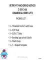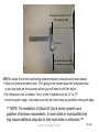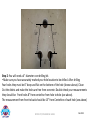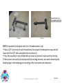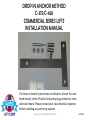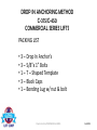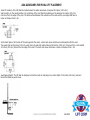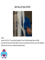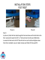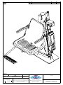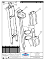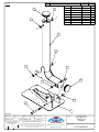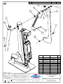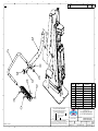
1
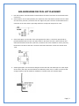
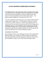
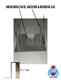
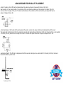
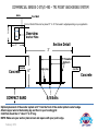
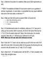
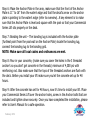
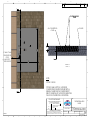
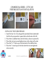
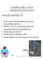
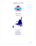
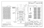
GLOBAL LIFT CORP Owner’s Manual Commercial Series C-375 Commercial Series C-450 684 N Port Crescent Rd Suite C Bad Axe, MI 48413 Toll Free: 866-712-0606 Fax: 989-269-5902 www.globalliftcorp.com Page | 1 COMMERCIAL SERIES POOL LIFTS C-375 C-450 TABLE OF CONTENTS INTRODUCTION PAGE – 3 ADA GUIDELINES FOR PLACEMENT PAGE – 4 24 VOLT BATTERY SYSTEM/WITH CONTROLS PAGE – 5 COMMERCIAL SERIES OPERATING INSTRUCTIONS PAGE – 6 UNIT MAINTENANCE AND CARE PAGE – 7 TROUBLESHOOTING PAGE – 8 WARRANTY INFORMATION PAGE – 9/10 WARRANTY REGISTRATION PAGE - 11 TRI POINT ANCHOR SYSTEM TRI POINT PAVER INSTRUCTION ANCHOR METHOD TRI POINT RETRO FIT ANCHOR SYSTEM TRI POINT DROP IN ANCHOR SYSTEM PORTABLE KIT INSTALLATION SEAT INSTALLATION Page | 2 INTRODUCTION Your Number One Choice for Commercial Pool Access Equipment Global Lift Corp. is located in Mid-Michigan, Global Lift Corp. prides itself in manufacturing top of line quality aquatic access equipment. Global Lift Corp's key staff has a century of combined industry experience and we take pride in each and every product that we build. Our Company is ISO Certified and our products are manufactured in the United States. Global Lift Corp. uses only the finest materials and processes to provide our customers with the highest quality products while still maintaining a price competitive edge. Page | 3 ADA GUIDELINES FOR POOL LIFT PLACEMENT 1. Pool Lift Location. Pool lifts shall be located where the water level does not exceed 48 inches (1220 mm). 2. Seat Location. In the raised position, the centerline of the seat shall be located over the deck and 16 inches (405 mm) minimum from the edge of the pool. The deck surface between the centerline of the seat and the pool edge shall have a slope not steeper than 1:48. 3. Clear Deck Space. On the side of the seat opposite the water, a clear deck space shall be provided parallel with the seat. The space shall be 36 inches (915 mm) wide minimum and shall extend forward 48 inches (1220 mm) minimum from a line located 12 inches (305 mm) behind the rear edge of the seat. The clear deck space shall have a slope not steeper than 1:48. 4. Submerged Depth. The lift shall be designed so that the seat will submerge to a water depth of 18 inches (455 mm) minimum below the stationary water level. To make sure the lift has enough clearance the lift should be installed at a location with 48” of Water depth Page | 4 24 VOLT BATTERY SYSTEMS WITH CONTROLS All of Global Lift Corp’s Commercial Series Lifts are equipped with a sealed 24 volt battery that is rechargeable. Along with a charging unit, hand held controller and control compartment. The 24 volt battery mounts right above the control compartment and the battery simply snaps in. The battery should be charged for 5-8 hours prior to the 1st use. The unit is operated by the 2 button easy to use controls. Staff will use the provided key to unlock the lift. The lock feature is located on the hand controls or front of the control box. Insert the key provided and turn to unlock the unit for use. (Avoid turning the key farther than 45 degrees as it will damage the key) Once unlocked, the arrow pointing down will lower the lift when depressed, the arrow that points up will raise the unit when depressed. If you hear the low battery indicator tone “Do Not Use the Lift” remove the battery from the unit and recharge the battery. RECHARGING THE BATTERY: Remove battery from the unit by unclipping from the control compartment. Place the battery in the charging unit. When the battery is charging the light will be illuminated, once fully charged the charge light will go off and then the battery is ready for use in your Commercial series pool lift. Page | 5 COMMERCIAL SERIES POOL LIFT OPERATING INSTRUCTIONS Prior to using the Commercial Series Pool Lift perform a test run of the lift empty. Once that is completed and the lift is back to original position, make sure that the arm lifts are in the up position and the seatbelt is unbuckled, once acknowledged you are ready! Once you are in the seat, buckle the seatbelt (make sure it is snug) and lower the arm rails. Before you attempt to operate the lift, make sure the pathway is clear from any obstacles. Once you have the 2 button easy controls in your hand, press the arrow that specifies down, keep in mind you don’t have to go to the bottom of the cycle, you can stop the lift whenever you deem comfortable to exit the lift. However when exiting the pool while on the lift, you should complete the cycle back to the top to have a completely safe exit from the pool. Once submerged into the pool, unbuckle the seatbelt and raise the armrest and slide off of the seat. Once you are done with your pool activity, make sure the seat is lowered sufficiently to allow you too easily slide back into the chair. Once you are seated, buckle the seatbelt and make sure that it is snug, lower the armrest. Next, to raise the lift chair out of the pool, make sure you press the button/arrow that represents up on the control. Apply continuous pressure until the lift comes to a complete stop at the end of the complete up cycle on the deck. You now can unbuckle the seatbelt and raise the arm rest and exit the unit. In the unlikely event that the lift does not return from the water using the hand control, have an attendant press the emergency return button on the front of the control box or on the underside of the control box and the lift will return to pool side. Page | 6 Maintenance Regular servicing will help prolong the life of your lift. Routine maintenance and cleaning is very important. The following is a routine maintenance you should follow. Daily o o o o o Check and charge battery if needed Test for normal operations Inspect your lift Clean and dry the lift and seat with clean water Cover lift after use Weekly o Overview Daily Checklist o Wipe away any surface rust with household spray cleaner o Clean tough stains with Scotchbrite pad and wipe clean Monthly o o o Inspects all connections, frame, seat etc., Clean battery connections Clean metallic surfaces with a wax cleaner Page | 7 The maintenance provision of the ADA states that “a public accommodation shall maintain in operable working condition those features of facilities and equipment that are required to be readily accessible to and usable by persons with disabilities" TROUBLESHOOTING GUIDE Before any troubleshooting commences make sure the battery has a full charge! (1) Does the lift raise or lower NO (a) Check the battery connection and reconnect (b) Check hand controls, make sure they are connected properly (c) Check for any lose wires on the control compartment (d) Check the connection cable for damage (e) Check to see that the lock on the hand control or front control box is in the unlocked position. (2) Did the lift stop moving over water and is stuck? Yes (a) Have a person or attendant push the emergency return button (b) The button is located on the front of the main control box or on the underside of the control box. The emergency button overrides the hand controls in case they have failed. Page | 8 (c) If the above does not work then recheck the battery, battery connection or the controls are not connected properly. Global Lift Corp Warranty Information The Commercial, Proformance, and Rotational series lifts have a Lifetime Limited Warranty on the metal components of the frame, not including the powder coating process. The Superior series lift has a 5 year structural limited warranty. Global Lift Corp warrants to the original retail end user only products manufactured by Global Lift Corp, when properly installed in accordance to the assembly and installation instructions, and when the equipment is properly used and maintained, be free from material defects and workmanship as stated below: Warranty starts from date of original purchase Metal structure (not including powder coat) – Lifetime Limited (Commercial/Proformance/Rotational Series) Metal structure (not including powder coat) 5 year limited structural warranty (Superior Series) Actuator and controls – 2 years from date of purchase then 2 years prorated Actuator and controls – 3 years 50% coverage (Customer is responsible for 50% of replacement cost Actuator and controls – 4 years 30% coverage (Customer is responsible for 70% of replacement cost Battery – 1 year from date of purchase This warranty does not cover damages to ANY of our lifts due to accident, abuse, negligence, misuse, damage by improper use of chemicals, fading, ice damage, fire, rust beyond structural damage( does not cover cosmetic rust), exceeding the weight capacity for model purchased, failure to install or to assemble the product in accordance with the installation and assembly instructions, normal wear and tear from day to day use, not maintained properly, if unit is altered or repaired without written approval of Global Lift Corp – All Warranties are Void. Page | 9 To commence the warranty claim process of a Global Lift Corp product, in writing provide place of purchase along with the product name and description, date of installation and a detailed description of the defect, along with a photo of the entire product and claimed defect. Prior to a 30 day period after receiving the written warranty claim by Global Lift Corp and barring any unforeseen delays the claimant will be notified of Global Lift Corp’s decision regarding the claim. If the request made by Global Lift Corp for the product to be returned to its factory or distributor of choice for inspection and/or repair, purchaser will be liable for “Freight Prepaid”. Global Lift Corp at its option will replace or repair the defective item and deliver the repaired product or replacement to the buyer of the product, freight prepaid by the purchaser to the destination on file in regards to the original order. Parts and Products returned for replacement to Global Lift Corp shall remain the property of Global Lift Corp under this limited warranty. A new warranty period shall not be established for any repaired or replaced products. Replaced or repaired products will remain under warranty only for the remainder of the original warranty period for the original product purchased. No person or organization is authorized to make any other specific or implied warranties on behalf of Global Lift Corp. THE WARRANTIES ARE IN LIEU OF ALL OTHER WARRANTIES, EXPRESSED OR IMPLIED, WHICH ARE HEREBY DISCLAIMED AND EXCLUDED, INCLUDING WITHOUT LIMITATION ANY WARRANTY OF MERCHANTABILITY OR FITNESS FOR A PARTICULAR PURPOSE OR USE. IN NO EVENT SHALL GLOBAL LIFT CORP BE LIABLE FOR ANY INCIDENTAL, CONSEQUENCIAL, INDIRECT, SPECIAL EXEMPLARY OR PUNITIVE DAMAGES OR LOST PROFITS FROM ANY BREACH OF THIS LIMITED WARRANTY.THE SOLE AND EXCLUSIVE REMEDY OF THIS WARRANTY IN REGARDS TO GLOBAL LIFT CORP’S PRODUCT SHALL BE LIMITED TO REPLACEMENT OR REPAIR AT A GLOBAL LIFT CORP’S FACILITY OR A DULY APPOINTED DISTRIBUTOR’S LOCATION OR AT A GLOBAL LIFT CORP’S DESIGNATED LOCATION. IN NO EVENT SHALL GLOBAL LIFT CORP LIABILITY EXCEED THE ENTIRE AMOUNT PAID TO GLOBAL LIFT CORP BY THE ORIGINAL PURCHASER IN REGARDS TO THE DEFECTIVE OR FAILED PRODUCT. NO REPRESENTATIVE OF GLOBAL LIFT CORP SUCH AS AGENTS, DISTRIBUTORS AND DEALERS HAS THE AUTHORITY TO ALTER IN ANY FASHION THE TERMS OF THIS WARRANTY AND GLOBAL LIFT CORP IS “NOT” RESPONSIBLE FOR REPRESENTATION, UNDERTAKING OR WARRANTY MADE BY ANY OTHER PERSON BEYOND THE WARRANTIES EXPRESSED SET FORTH IN THIS WARRANTY. Page | 10 Warranty Procedure Warranty Claims shall be submitted to Global Lift Corporation by the distributor which originated the sale with Global Lift Corporation or directly to Global Lift Corporation. All RGA (Return Goods Authorization) documents shall be requested by and issued only to the distributor which originated the sale or directly to Global Lift Corporation. Global Lift Corporation shall determine warranty coverage validation and replacement parts or repair, which were directed to the distributor which originated the sale or that are initiated directly with Global Lift Corporation. Warranty claims received from end users by Global Lift Corporation shall be re-directed to the distributor which originated the sale with Global Lift Corporation or processed directly by Global Lift Corporation. Page | 11 GLOBAL LIFT CORP WARRANTY REGISTRATION PURCHASED BY: Company Name:__________________________________Contact:____________________ City: ______________________________ State: ___________ Zip: ___________ Phone: (_____) ______________________________ DEALER: Name: ____________________________Phone Number___________________ City: __________________________ State: _______________ Zip: ___________ Phone: (_____) ______________________________ Model: __________________________ Serial Number: ____________________ Color: _______________ Purchase Price: $ _______ Date Purchased: ___________ I have read and I accept the warranty terms. Signature: ______________________________________ Date: ______________ This card must be completed and returned to Global Lift Corp within 30 days of purchase date to assure coverage. Please mail to: Global Lift Corp, 684 N Port Crescent Suite C, Bad Axe, MI 48413 Page | 12 COMMERCIAL SERIES LIFTS TABLE OF CONTENTS 1. 2. 3. 4. 5. 6. February 2012 TRI-Point Anchor System TRI-Point Paver Instruction Anchor Method TRI-Point Retro-Fit Anchor System TRI-Point Drop In Anchor System Commercial Series Portable Kit Seat Installation COMMERCIAL SERIES LIFTS C-375/C-450 TRI-POINT ANCHORING SYSTEM New Construction or Saw Cut INSTALLATION MANUAL Patent Pending February 2012 COMMERCIAL SERIES C-375/C-450 TRI-POINT ANCHORING SYSTEM INSTALLATION Patent Pending PARTS LIST 1 3 3 3 February 2012 – Anchor Plate with bonding Lug & bolt 5/8” x 1” Stainless Steel Bolts 6” Anchoring Rods Plastic Caps ANCHORING PLATE, ANCHORS & BONDING LUG 5/8” x 1” Bolts February 2012 ADA GUIDELINES FOR POOL LIFT PLACEMENT •Pool Lift Location. Pool lifts shall be located where the water level does not exceed 48 inches (1220 mm). Seat Location. In the raised position, the centerline of the seat shall be located over the deck and 16 inches (405 mm) minimum from the edge of the pool. The deck surface between the centerline of the seat and the pool edge shall have a slope not steeper than 1:48. •Clear Deck Space. On the side of the seat opposite the water, a clear deck space shall be provided parallel with the seat. The space shall be 36 inches (915 mm) wide minimum and shall extend forward 48 inches (1220 mm) minimum from a line located 12 inches (305 mm) behind the rear edge of the seat. The clear deck space shall have a slope not steeper than 1:48. •Submerged Depth. The lift shall be designed so that the seat will submerge to a water depth of 18 inches (455 mm) minimum below the stationary water level. February 2012 COMMERCIAL SERIES C-375/C-450 – TRI POINT ANCHORING SYSTEM Water Pool Wall Front of Anchor Plate can be placed 11” to 16” from water’s edge depending on you application Overview 3’ Anchor Plate Section Detail 3’ 3’ 6” Threaded Anchor’s Cold Pin Concrete COMPACT SAND 6” Bonding Lug Cold Pin Concrete 5/8 Bolts Optimal placement of the anchor system is 13” from the front of the anchor plate to water’s edge. Attach copper wire to the bonding lug and then to your bonding grid Cold Pin’s should be ½” rebar 6” to 8” long NOTE: Make sure your anchor plate is level and square with your pool’s edge. February 2012 Step 1: Determine the location for installation (Make sure all ADA requirements are met). ***NOTE: The installation of Global Lift Corp’s anchor system’s are a guideline of minimum requirements. In some states or municipalities they may require additional steps due to their local codes or ordinances.*** Step 2: Make sure that all the parts are present (Refer to the parts list) 1 - Anchor Plate with Bonding Lug & bolt 3 - 5/8” x 1” Stainless Steel Bolts 3 - 6” Anchors Step 3: At the determined location for installation, chalk out a 3’ X 3’ area prior to cutting out the concrete. (Refer to overview, the front of the Anchor Plate must be 11” to 16” from the water’s edge and 6” deep). New Construction, the concrete must be 6” deep with a ½” reinforcing rod, minimum of an 18” grid. NOTE: Make sure all local codes and ordinances are met. Step 4: Once the 3’ X 3’ area is cut out, make sure you drill in the inner wall of all 4 sides of the area (refer to the section detail) for the purpose of cold pinning the new concrete to the old concrete. Use 1/2” rebar, 6” to 8” in length. Step 5: Attach the 3 – 6” threaded anchor’s with the 5/8” x 1” bolts (included) to the Anchor Plate and tighten down. February 2012 Step 6: Place the Anchor Plate in the area, make sure that the front of the Anchor Plate is 11” to 16” from the water’s edge and that the decal’s arrow on the anchor plate is pointing to the water’s edge (refer to overview). A key element is to make sure that the Anchor Plate is level and square with the pool so that your Commercial Series Lift sits properly on the deck. Step 7: Bonding the unit – The bonding lug is included with the Anchor plate (furthest point from the pool wall on the Anchor Plate) locate the bonding lug, connect the bonding lug to the bonding grid. NOTE: Make sure all local codes and ordinances are met. Step 8: Pour in your concrete, (make sure you cover the holes in the 3 threaded anchor’s so you don’t get concrete in the threads) minimum of 4,000 psi with reinforcing rod. Also make sure that the tops of the threaded anchors are flush with the deck. Before you install your lift make sure you let the concrete set up for 48 hours. Step 9: After the concrete has set for 48 hours, now it’s time to install your lift. Place your Commercial Series Lift over the anchor holes, screw in the Anchor bolts that are included and tighten down securely. Once you have completed the installation, please refer to User’s Manual for a safe operation. February 2012 8 5 6 7 4 2 3 REV. 1 DESCRIPTION DATE APVD. G TRI-POINT ANCHOR SYSTEM D 4' X 4' CONCRETE PAD 6" THICK D 4" PAVERS C C 4" 4' 12" MIN & 17" MAX FROM THE FRONT OF THE ANCHOR TO THE POOL EDGE 6" 4' SECTION G-G SCALE 1 : 12 B B NOTES OPTION 1: SHOWN OPTION 2: SAME AS OPTION 1, JUST RECESS CONCRETE PAD DOWN PER THE PAVER DEPTH & REINSTALL PAVERS OVER THE CONCRETE EXCEPT DIRECTLY UNDER THE LIFT. THAT SECTION NEEDS TO BE THE 6" SOLID CONCRETE FOR LOAD PURPOSES. G TITLE: DO NOT SCALE DRAWING A X. = .125 XX. = .094 XXX. = .062 FRACTIONAL DIMENSIONS .125 FILLET RADII .000 THRU +.094 HOLES .000 THRU .015 ANGLES 1 PROPRIETARY AND CONFIDENTIAL THE INFORMATION CONTAINED IN THIS DRAWING IS THE SOLE PROPERTY OF Global Lift Corporation. ANY REPRODUCTION IN PART OR AS A WHOLE WITHOUT THE PERMISSION OF Global Lift Corp. IS PROHIBITED. MATERIAL: 8 7 6 5 4 3 A TRI-POINT INSTALLATION PAVERS UNLESS OTHERWISE SPECIFIED DIMENSIONS ARE IN INCHES TOLERANCES ARE: 684 N. Port Crescent, Suite C DWG. NO. Bad Axe, MI 48413 PAVER INSTALLATION SCALE: 1:12 DATE: 8/13/2012 DWR: B.E. APVD. BY: S.S. 2 1 REV 100 COMMERCIAL SERIES LIFTS C-375/C-450 RETRO-FIT ANCHORING METHOD INSTALLATION MANUAL RETRO-FIT/COMMERCIAL SERIES Feb 2012 RETRO-FIT ANCHORING METHOD C-375/C-450 COMMERCIAL SERIES LIFTS PACKING LIST • 3 – Threaded Anchor’s with base • 3 – 5/8” Nuts • 3 – 5/8”x 1” Bolts • 3 – Bonding lugs w/nut & bolts • 3 – Plastic Caps • 1 – T – Shaped Template RETRO-FIT/COMMERCIAL SERIES Feb 2012 ADA GUIDELINES FOR POOL LIFT PLACEMENT •Pool Lift Location. Pool lifts shall be located where the water level does not exceed 48 inches (1220 mm). Seat Location. In the raised position, the centerline of the seat shall be located over the deck and 16 inches (405 mm) minimum from the edge of the pool. The deck surface between the centerline of the seat and the pool edge shall have a slope not steeper than 1:48. •Clear Deck Space. On the side of the seat opposite the water, a clear deck space shall be provided parallel with the seat. The space shall be 36 inches (915 mm) wide minimum and shall extend forward 48 inches (1220 mm) minimum from a line located 12 inches (305 mm) behind the rear edge of the seat. The clear deck space shall have a slope not steeper than 1:48. •Submerged Depth. The lift shall be designed so that the seat will submerge to a water depth of 18 inches (455 mm) minimum below the stationary water level. RETRO-FIT/COMMERCIAL SERIES Feb 2012 Distance must be 12” to 17” From water’s edge Front Holes Hole’s parallel with pool’s edge STEP 1: Locate the retro-fit anchoring system template (included and shown above) • Once you determine where your lift is going to be located place the template down so you can mark on the concrete where you will need to drill the holes. • The dimensions are as follows: Front of the Template must be 12” to 17” from the water’s edge, also make sure that the front holes are parallel to the pools edge. ***NOTE: The installation of Global Lift Corp’s anchor system’s are a guideline of minimum requirements. In some states or municipalities they may require additional steps due to their local codes or ordinances.*** RETRO-FIT/COMMERCIAL SERIES Feb 2012 15” 15” 8” Step 2: You will need a 4” diameter core drilling bit. • Make sure you have accurately marked your hole location to be drilled. After drilling Your holes they must be 6” deep and flat on the bottom of the hole (shown above). Clean Out the debris and make the holes are free from concrete. Double check your measurements they should be: Front holes 8” from centerline from hole to hole (see above). The measurement from front to back should be 15” from Centerline of each hole (see above) RETRO-FIT/COMMERCIAL SERIES Feb 2012 Note: Anchor must be Electrically bonded. Please See the NEC requirements. Picture B Picture A STEP 3: Assemble the template with the 3 threaded anchor rods. • Place a 5/8” nut on top of each threaded rod, then place the template on top and bolt Down with the 5/8” bolts provided (refer to picture A). • Place the assembly in your drilled holes as shown in picture B. make sure that the top Of the anchor rods are flush and level with the existing concrete, also with connecting the Bonding lugs to the bonding grid according to the local codes and ordinances RETRO-FIT/COMMERCIAL SERIES Feb 2012 Picture B Picture A STEP 4: Cementing the anchor in the concrete. • You will need 20lbs of Quick dry Anchoring Cement (Commercial Grade Quikrete Exterior Use Anchoring Cement) to complete the installation. You can purchase at any hardware store in your area. Read the label and follow manufacturer’s instructions. • Start pouring into the 3 holes evenly until you fill them up, make sure not to overfill the Holes so that it does not create more work to scrap excess concrete off. • Let the concrete set for 24hrs, Remove the template then sand the area with a sand stone to smooth the finish. Make sure the anchor’s are flush with the concrete (picture B) • You are now ready to install your Commercial Series lift. RETRO-FIT/COMMERCIAL SERIES Feb 2012 DROP IN ANCHOR METHOD C-375/C-450 COMMERCIAL SERIES LIFTS INSTALLATION MANUAL The Drop In Anchor System does not allow for a bond. You can Bond directly to the lift with the bonding lug provided or some alternate means. Please contact your local electrical inspector Before installing any anchoring systems Drop In Anchor/COMMERCIAL SERIES Feb 2012 DROP IN ANCHORING METHOD C-375/C-450 COMMERCIAL SERIES LIFTS PACKING LIST • 3 – Drop In Anchor’s • 3 – 5/8”x 1” Bolts • 1 – T – Shaped Template • 3 – Black Caps • 1 – Bonding Lug w/ nut & bolt Drop In Anchor/COMMERCIAL SERIES Feb 2012 ADA GUIDELINES FOR POOL LIFT PLACEMENT •Pool Lift Location. Pool lifts shall be located where the water level does not exceed 48 inches (1220 mm). Seat Location. In the raised position, the centerline of the seat shall be located over the deck and 16 inches (405 mm) minimum from the edge of the pool. The deck surface between the centerline of the seat and the pool edge shall have a slope not steeper than 1:48. •Clear Deck Space. On the side of the seat opposite the water, a clear deck space shall be provided parallel with the seat. The space shall be 36 inches (915 mm) wide minimum and shall extend forward 48 inches (1220 mm) minimum from a line located 12 inches (305 mm) behind the rear edge of the seat. The clear deck space shall have a slope not steeper than 1:48. •Submerged Depth. The lift shall be designed so that the seat will submerge to a water depth of 18 inches (455 mm) minimum below the stationary water level. Drop In Anchor/COMMERCIAL SERIES Feb 2012 Distance must be 12 to 17”” From water’s edge Front Holes Hole’s parallel with water’s edge STEP 1: Locate the Drop In anchoring system template (included and shown above) • Once you determine where your lift is going to be located place the template down So you can mark on the concrete where you will need to drill the holes. • The dimensions are as follows: Front of Template must be 12” to 17” From the water’s edge. Also make sure that the front holes are parallel to the pools edge. ***NOTE: The installation of Global Lift Corp’s anchor system’s are a guideline of minimum requirements. In some states or municipalities they may require additional steps due to their local codes or ordinances.*** Drop In Anchor/COMMERCIAL SERIES Feb 2012 15.00 8.00 15.00 Step 2: You will need a 7/8” rock carbide drilling bit. • Make sure you have accurately marked your hole location to be drilled. After drilling Your holes they must be 2 1/2” deep. Double check your measurements they should be: Front holes 8” from centerline from hole to hole (see above). The measurement from front to back should be 15” from Centerline of each hole (see above). Clean hole with pressurized Air or a vacuum. Drop In Anchor/COMMERCIAL SERIES Feb 2012 Picture A Picture B STEP 3: • Administer Epoxy into the hole prior to inserting the drop in anchor. • Drive the anchor flush with the surface of concrete (shown in picture A) • Expand the anchor with the setting tool (provided). Anchor is properly expanded when shoulder of the setting tool is flush with the top of the anchor (shown in picture B). • Global Lift has provided a bonding lug that you will need to drill & attach to the lift, due to there is no means to bond to the drop in anchor’s. Please check local & state codes. • Now you are ready to install your Commercial Series Lift. Drop In Anchor/COMMERCIAL SERIES Feb 2012 GLOBAL LIFT CORP C-375/C-450 COMMERCIAL SERIES PORTABLE KIT Portable Kit - www.globalliftcorp.com Feb 2012 COMMERCIAL SERIES C-375/C-450 PORTABLE KIT PARTS LIST • 4 – 1/4 x 3/4” Carriage Bolts w/ lock nuts • 2 – 5/16 x ¾” Bolts w/ lock nuts • 6 – Lock Nuts • 2 – Stabilizer Bars • 1 – Lifting Unit • 1 – Screw w/ washer • 4 – 1” round caps • 2 – 2”x 3” caps • 2 – 1” x 1” square caps Portable Kit - www.globalliftcorp.com Feb 2012 COMMERCIAL SERIES – C375/C-450 PORTABLE KIT EASY INSTALLATION • INSTALLING THE STABILIZER BARS 1. Insert the four 1/4 x 3/4 carriage bolts (provided) from underneath the lift in the pre-punched square holes on both ends of the lift. 2. Place the two stabilizer bars onto the bolts (as shown in picture B). 3. Place the Lock nuts on and tighten down with a deep well socket. 4. Place the 2”x 3” black cap on the backside of the stabilizer bars. 5. Place the 1” round caps in the holes after the nuts are tightened down securely. Feb 2012 Portable Kit - www.globalliftcorp.com COMMERCIAL SERIES – C375/C450 PORTABLE KIT EASY INSTALLATION • INSTALLING THE LIFTING UNIT 1. On the “opposite” side of the stabilizer bars locate the 2. 3. 4. 5. four pre-punched square holes. Place the 2 – 5/16 x 3/4” carriage bolts (provided) in the pre-punched square holes from underneath the lift. Place the lifting unit on the bolts Place the lock nuts on and tighten securely. Place the lifting unit’s cover on and secure with screws provided. Lifting Unit Feb 2012 Portable Kit - www.globalliftcorp.com COMMERCIAL SERIES – C375/C450 PORTABLE KIT EASY OPERATION • OPERATING THE COMMERCIAL SERIES PORTABLE KIT Once you make sure all the components are securely fastened, Locate the operating handle on The portable kit. When your lift is in use, the portable kit should be in the up Position and the lift is secured to the deck with the 3 anchor Bolts. Once you are ready to store your lift, remove the 3 Anchor bolts, push down on the Lifting Unit’s handle, the lift will raise and then you are able to roll with ease to your storage location. Portable Kit - www.globalliftcorp.com Feb 2012 GLOBAL LIFT CORP CUSTOM SEAT INSTALLATION MANUAL C, P & S Series Lifts GLOBAL LIFT CORP CUSTOM SEAT INSTALLATION MANUAL PARTS LIST 1 - Custom Seat 1 - Foot Rest 2 – Arm Rests 1 - Seat Belt & Buckle 1 – ½” x 2 3/4” Securing Bolt 3 – 5/16 x 3” Attaching Pin with lock nut 1 – 5/16 x 2” Foot Rest attaching bolt w/ nut 1 – 2” Round cap 1 – 1” Round cap INSTALLATION STEPS Picture A Step 1: Unpack your custom seat (picture A). Loose Items will consist of: • • • Foot Rest and Tube ½” x 3” Bolt w/ lock nut 5/16” x 2 ¾” Bolt with Lock nut INSTALLATION STEPS Picture A Picture B Step 2: Align your custom seat (Picture A), slide the lower seat tube into the upper Seat tube. Step 3: Once you have the seat in place, take your ½” x 3” bolt and slide it through the pre-drilled Holes (Picture B). Once you have inserted the bolt all the way through, apply the locking nut (supplied) and tighten down. INSTALLATION STEPS Step 4: Locate the 5/16 x 3” securing bolt (supplied), insert the bolt through the pre-drilled Seat and tube holes (As shown Above). Once you have the bolt inserted, secure the installation With the lock nut that is provided and tighten down. INSTALLATION STEPS FOOT REST Picture A Picture B Step 5: In picture A, slide the foot tube through the foot rest sleeve and line the hole to the Slot. In picture B, locate the 5/16” x 2” bolt and insert into the pre-drilled holes to secure the foot rest to the lift. Place the lock nut on the bolt and tighten down. Once that is complete, you are ready to enjoy your Global Lift Corp pool lift. REV. NOTES: DESCRIPTION DATE APVD. MATERIAL: SCALE: 1:6 REV: 100 WEIGHT: LBS MACH WEIGHT: LBS DO NOT SCALE DRAWING UNLESS OTHERWISE SPECIFIED DIMENSIONS ARE IN INCHES TOLERANCES ARE: X. = .125 FRACTIONAL DIMESIONS XX. = .062 FILLET RADII .000 THRU + .094 XXX. = .031 HOLES .000 THRU .015 ANGLES 1 DEGREE DATE: 12/12/2012 .125 DWR: B.E. TITLE: C-375 APVD BY: J.I. PROPRIETARY AND CONFIDENTIAL THE INFORMATION CONTAINED IN THIS DRAWING IS THE SOLE PROPERTY OF Global Lift Corporation. ANY REPRODUCTION IN PART OR AS A WHOLE WITHOUT THE WRITTEN PERMISSION OF Global Lift Corp. IS PROHIBITED. 684 N. Port Crescent, Suite C Bad Axe, MI 48413 DWG. NO. ASSEMBLY MANUAL NOTES: REV. 6 6 DESCRIPTION DATE APVD. 6 1 2 3 6 4 5 ITEM NO. PART # DESCRIPTION QTY. 1 CGLCAS-0 BRACKET 1 2 ACT23CS-1 SKF ACTUATOR 1 3 ACT23CS-2 SKF BATTERY PACK 1 4 H-CLAMP Resizable Band Clamp 2 5 ACT23CS-5 SKF CONTROL BOX 1 6 BOLT-M6-25 BOLT 4 DATE: 12/12/2012 DWR: B.E. SCALE: 1:4 REV: 100 WEIGHT: LBS MACH WEIGHT: LBS DO NOT SCALE DRAWING UNLESS OTHERWISE SPECIFIED DIMENSIONS ARE IN INCHES TOLERANCES ARE: X. = .125 FRACTIONAL DIMESIONS XX. = .062 FILLET RADII .000 THRU + .094 XXX. = .031 HOLES .000 THRU .015 ANGLES 1 DEGREE .125 4 C-375 SKF ACTUATOR & BATTERY INSTALLATION TITLE: APVD BY: J.I. PROPRIETARY AND CONFIDENTIAL THE INFORMATION CONTAINED IN THIS DRAWING IS THE SOLE PROPERTY OF Global Lift Corporation. ANY REPRODUCTION IN PART OR AS A WHOLE WITHOUT THE WRITTEN PERMISSION OF Global Lift Corp. IS PROHIBITED. 684 N. Port Crescent, Suite C Bad Axe, MI 48413 DWG. NO. SKFACTBATASM REV. NOTES: DESCRIPTION DATE ITEM NO. 6 4 4 PART # QTY. 1 CGLCBP-0 BASE PLATE 1 2 PGLCMB-0 MAIN BEAM 1 3 BUSH625-625 BUSHING 2 4 BUSH75-5 BUSHING 2 5 BUSH625-344 BUSHING 2 6 PLASCAP-4 PLASTIC CAP 2 7 BOLT625-11-6.5 BOLT 1 8 NUT625-11 NUT 1 2 5 5 3 6 3 8 7 1 MATERIAL: SCALE: 1:6 REV: 100 WEIGHT: LBS MACH WEIGHT: LBS DO NOT SCALE DRAWING UNLESS OTHERWISE SPECIFIED DIMENSIONS ARE IN INCHES TOLERANCES ARE: X. = .125 FRACTIONAL DIMESIONS XX. = .062 FILLET RADII .000 THRU + .094 XXX. = .031 HOLES .000 THRU .015 ANGLES 1 DEGREE DATE: 12/12/2012 .125 DWR: B.E. C-375, P-375 MAIN BEAM TO BASE PLATE ASSEMBLY TITLE: APVD BY: J.I. PROPRIETARY AND CONFIDENTIAL THE INFORMATION CONTAINED IN THIS DRAWING IS THE SOLE PROPERTY OF Global Lift Corporation. ANY REPRODUCTION IN PART OR AS A WHOLE WITHOUT THE WRITTEN PERMISSION OF Global Lift Corp. IS PROHIBITED. 684 N. Port Crescent, Suite C Bad Axe, MI 48413 APVD. DESCRIPTION DWG. NO. CGLCMBEXPLD REV. NOTES: DESCRIPTION DATE APVD. 5 6 4 3 7 8 2 9 1 6 10 11 8 12 MATERIAL: NOTED SCALE: 1:6 REV: 100 WEIGHT: LBS MACH WEIGHT: LBS DO NOT SCALE DRAWING UNLESS OTHERWISE SPECIFIED DIMENSIONS ARE IN INCHES TOLERANCES ARE: X. = .125 FRACTIONAL DIMESIONS XX. = .062 FILLET RADII .000 THRU + .094 XXX. = .031 HOLES .000 THRU .015 ANGLES 1 DEGREE DATE: 12/12/2012 .125 ITEM NO. PART # DESCRIPTION QTY. 1 GLCSEATB-TOP SEAT TUBE TOP 1 2 PLASCAP-2.25 PLASTIC CAP 1 3 BUSH75-375 BUSHING 1 4 PGLCSS-0 SEAT LEVELER 1 5 NUT75-10 NUT 1 6 NUT5-13 NUT 2 7 PGLCSS-10 HOCKEY STICK 1 8 BUSH5-375 BUSHING 2 9 WASHER-50 WASHER 1 10 BOLT25-20-3 BOLT 1 11 WASHER-25 WASHER 1 12 NUT25-20 NUT 1 DWR: B.E. TITLE: APVD BY: J.I. PROPRIETARY AND CONFIDENTIAL THE INFORMATION CONTAINED IN THIS DRAWING IS THE SOLE PROPERTY OF Global Lift Corporation. ANY REPRODUCTION IN PART OR AS A WHOLE WITHOUT THE WRITTEN PERMISSION OF Global Lift Corp. IS PROHIBITED. 684 N. Port Crescent, Suite C Bad Axe, MI 48413 C-375, P-375 SEAT TUBE, SEAT LVELER & HOCKEY STICK ASSEMBLY DWG. NO. MVMNTCMPNTS REV. NOTES: DESCRIPTION DATE APVD. 1 2 3 2 2 3 MATERIAL: SCALE: 1:8 REV: 100 WEIGHT: LBS MACH WEIGHT: LBS DO NOT SCALE DRAWING UNLESS OTHERWISE SPECIFIED DIMENSIONS ARE IN INCHES TOLERANCES ARE: X. = .125 FRACTIONAL DIMESIONS XX. = .062 FILLET RADII .000 THRU + .094 XXX. = .031 HOLES .000 THRU .015 ANGLES 1 DEGREE DATE: 12/12/2012 .125 3 ITEM NO. PART # DESCRIPTION QTY. 1 GLCSEATB-1 PLASTIC SEAT 1 2 NUT313-18 NUT 3 3 BOLT313-18-3 BOLT 3 DWR: B.E. TITLE: APVD BY: J.I. SEAT INSTALLATION PROPRIETARY AND CONFIDENTIAL THE INFORMATION CONTAINED IN THIS DRAWING IS THE SOLE PROPERTY OF Global Lift Corporation. ANY REPRODUCTION IN PART OR AS A WHOLE WITHOUT THE WRITTEN PERMISSION OF Global Lift Corp. IS PROHIBITED. 684 N. Port Crescent, Suite C Bad Axe, MI 48413 DWG. NO. STINSTL 8 5 6 7 4 2 3 REV. NOTES 1 DESCRIPTION DATE APVD. D D 3 2 C C 1 5 4 10 6 B 7 B 8 7 ITEM NO. PART # DESCRIPTION QTY. 1 2 3 4 5 6 7 8 9 10 GLCSEATB-7 GLCSEATB-BOTTOM NUT-M12 BOLT-M12-70 NUT375-16-2 PLASCAP-1 NUT313-18 BOLT375-16-1.75 BOLT313-18-1.75 PLASCAP-2 TITLE: FOOT REST TUBE SEAT SUPPORT BOTTOM NUT BOLT NUT PLASTIC CAP NUT BOLT BOLT PLASTIC CAP 1 1 2 1 1 1 2 1 2 1 9 9 DO NOT SCALE DRAWING A C-375, P-375 FOOT REST TUBE, SEAT TUBE & FOOT REST INSTALLATION UNLESS OTHERWISE SPECIFIED DIMENSIONS ARE IN INCHES TOLERANCES ARE: X. = .125 XX. = .094 XXX. = .062 FRACTIONAL DIMENSIONS .125 FILLET RADII .000 THRU +.094 HOLES .000 THRU .015 ANGLES 1 PROPRIETARY AND CONFIDENTIAL THE INFORMATION CONTAINED IN THIS DRAWING IS THE SOLE PROPERTY OF Global Lift Corporation. ANY REPRODUCTION IN PART OR AS A WHOLE WITHOUT THE PERMISSION OF Global Lift Corp. IS PROHIBITED. MATERIAL: NOTED 8 7 6 5 4 3 684 N. Port Crescent, Suite C DWG. NO. Bad Axe, MI 48413 SCALE: 1:5 WEIGHT: LBS STTBFTRSTINSTL DATE: 12/12/2012 DWR: B.E. MACH WEIGHT: LBS 2 APVD. BY: J.I. 1 REV 100 A