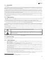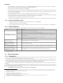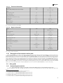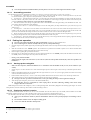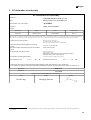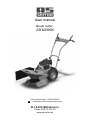
1
User manual Brush cutter AS 620KM From serial number:: 022209100001 EN – translation of the original instructions D-74424 Bühlertann Phone (07973) 9123-0 www.as-motor.de EN English Contens 1 User manual 2 Pictures 3 EC declaration of conformity 4 14 19 Basic information As part of the pre-sale servicing ask your dealer to unwrap the machine and give you a brief training on how to use it! AS 620KM Type Engine type HONDA GCV-190 Serial number1 Delivery date - date of sale Supplier (stamp) ● 1 You are advised to make a copy of this page with filled in information about the machine’s purchase in case the original manual is lost. Fill in the plate number from the name plate or stick the indentification label. 3 AS 620KM 1 User manual Contens 1 User manual 4 1.1 Introduction.....................................................................................5 1.1.1 Basic warning........................................................................5 1.2 Operation safety..............................................................................5 1.2.1 Safety regulations..................................................................5 1.2.2 Noise and vibration values....................................................6 1.2.3 Safety pictograms..................................................................6 1.3 Basic information............................................................................6 1.3.1 Intended use...........................................................................6 1.3.1.1 Technical information..................................................7 1.3.1.2 Engine information .....................................................7 1.3.2 Description of the machine and its parts...............................7 1.4 User guide........................................................................................7 1.4.1 Assembling the machine........................................................7 1.4.1.1 Assembling procedure.................................................8 1.4.2 Putting into operation............................................................8 1.4.2.1 Starting up the cutting disc..........................................8 1.4.2.2 Putting the machine in motion....................................8 1.4.2.3 Machine stopping........................................................9 1.4.2.4 Travel speed selection.................................................9 1.4.3 Work with the machine..........................................................9 1.4.3.1 Cutting width...............................................................9 1.4.3.2 Methods of stand cutting.............................................9 1.4.3.2.1 Cutting problems...............................................9 1.5 Maintenance, servicing and storage..............................................10 1.5.1 Travelling wheels................................................................10 1.5.1.1 Tyre pressure.............................................................10 1.5.2 Machine lubrication.............................................................10 1.5.2.1 Engine oil exchange..................................................10 1.5.2.2 Lubricating points.....................................................10 1.5.3 Work blades service and exchange......................................10 1.5.4 Belt transmission – automatic brake...................................11 1.5.4.1 Tightening pulleys adjustment...................................11 1.5.4.1.1 V-belt exchange...............................................11 1.5.4.2 Brake function control and adjustment.....................11 1.5.5 Service intervals..................................................................12 1.5.6 Problems and solutions........................................................12 1.5.7 Storage.................................................................................13 1.5.7.1 Machine washing and cleaning.................................13 1.5.8 Packaging and machine disposal after its service life termination.....................................................................................13 The manufacturer reserves the right for changes and innovations which do not influence the function and safety of the machine. These changes do not have to be reflected in this user manual. Misprints reserved. 4 EN English 1.1 Introduction Dear customer We congratulate you on your purchase decision. With the AS brush cutter you got a reliable and high-quality machine well-proven in practice for years. We continue to improve our machines. Everywhere you want to cut grass of any height, weeds and shrubbery, no matter if on meadows, in orchards, on horse lots or on municipal areas, you can count on the reliable help of your new AS brush cutter. It is a specialist for such tasks. It cuts large areas with dense and high grass stand in the shortest time, it copes with uneven areas as well as slopes and embankments. Familiarize yourself with the control of your brush cutter to be able to work with it safely. That’s why we prepared these instructions for you. It is necessary to read the safety instructions in the next chapter! They protect your health. In the following chapters you will learn everything important about your AS brush cutter, about its usage and care of it. Because even the AS brush cutter can provide you with the best performance and work for many years only if you treat it correctly and you follow the regulations about maintenance and care. Should you have any questions regarding your brush cutter, please contact your dealer or AS-Motor directly. We are pleased to help you and we are also grateful for improvement suggestions. And one more wish: take your neighbours into consideration and cut only in weekdays between 7.00 and 13.00 and between 15.00 and 19.00. According to a regulation for protection against noise from 1.8.1987, it is forbidden to cut on Sundays, on feast days and out of the above-mentioned periods of time. In addition, different regulations can be valid in different regions (noon rest). Now we wish you pleasant work with your AS brush cutter. The right, left, front and rear sides are defined from the view and place of the operator in this manual. The operator always stands in the travel direction behind the brush cutter handlebars. 1.1.1 Basic warning The user must be familiar with this user guide and follow all machine operation instructions, so that there are no risks to health and property of the user, as well as other persons. Safety instructions published in this guide do not describe all possibilities, conditions and situations that can occur in reality. Safety factors, such as common sense, carefulness and attention, are not included in this manual. However, every person handling or servicing the machine is presumed to have these. Only mentally and physically healthy persons can work with this machine. In case the machine is used for professional application, the owner of the machine must provide its attendants work safety training and carry out training about operating the machine. The owner must also keep records of these training sessions. If you find any of the information in this guide incomprehensible, contact your dealer2 or the machine manufacturer3. The user manuals with which this machine is equipped are an integral part of the machine. They have to be available at any time, safely deposited in an accessible place where there is no risk of their destruction. If the machine is sold to another person, the user guides must be given to the new owner. The manufacturer bares no responsibility for any risks, dangers, accidents and injuries that occur while the machine is operated, in case the conditions aforementioned are not followed. The manufacturer bears no responsibility for damages caused by unauthorised use, improper machine operation, and damages caused by any unauthorised modification of the machine. In order to prevent injury risks to yourself or other persons, or property damage, it is especially important to follow the safety instructions. These instructions are marked by the following safety warning symbol: If you see this symbol in the manual, read the following information carefully! This international safety symbol indicates important safety information. When you see this symbol, watch out for an injury possibility concerning yourself or other persons and read the following information carefully. Tab. 1: Symbols 1.2 Operation safety The machine is designed to protect its attendant from parts flying off the cut area. Do not remove any passive nor active safety elements. By doing so you expose yourself to risk of injury. 1.2.1 Safety regulations Machine attendants have to be aged 18 or over. The attendant must be familiar with the machine user manual and have knowledge of general work safety principles. Before each machine use check all its parts (especially the operating mechanism and its covers) to see if they aren't loose or damaged. Revealed defects parts must be rectified immediately. For repairs, use the original spare parts only. Do not start the engine in closed spaces! Pay special attention when handling the machine. The engine exhaust muffler remains hot after the engine is switched off. While adding the fuel, make sure it does not leak or spill over engine parts. If the fuel is spilled, dry the soiled parts or wait for the fuel to evaporate. Always switch off the engine and wait for the cutting disk to stop before starting any activity near the machine! Always switch the engine off before leaving the machine! Never leave the engine running at the maximum engine speed or running idle for a long time while the clutches of the cutting disk drive and wheel drive are turned off. The machine drive parts could be damaged (V-belt, belt pulley, clutch pulley, etc.)! Remove any solid parts form the stand before cutting (such as stones, wires, loose construction leftovers, etc.), as these could be thrown away or damage the machine. If these parts cannot be removed, avoid them. The machine is equipped with a rotating implement. Maximum circumferential speed is 64 m.s-1. It is therefore important to keep other persons at a safe distance while the machine is operating (there is a possibility of the cut stand or solid objects chipping off)! 2 3 Fill the dealer’s address into the table at the beginning of the manual (unless it is already filled in by the dealer). The machine manufacturer's address is given at the end of this manual. 5 AS 620KM When the machine is being operated, all other persons (especially children) and animals must stay out of the machine's workspace. The machine attendant can only continue working after taking these into a safe 4 distance. Keep a safe distance form the machine given by its handlebars. When operating the machine, use work aids approved by EN 166 or EN 1731 (tight clothes, firm shoes, work gloves and protective glasses). Protect your ears with appropriate safety devices according to EN 352-1 (shell-shaped ear protectors) or EN 352-2 (plug ear protectors). Ask your dealer for these safety devices. Safe climbing ability of the machine is 10º. Maximum engine tilt while working is 20º for long and 30º for short periods5 . Do not use the machine on wet grass. Always work on safe terrain. Walk - never run - when working. Be careful, especially when changing directions on slopes. Do not cut stands on steep slopes. If you fall, let the machine, go do not hold it. It is forbidden to remove any protective devices and covers from the machine. Any machine repairs, adjustments, greasing and cleaning is to be carried out when the machine is turned off and the spark plug is disconnected. 1.2.2 Noise and vibration values ➢ Declared emission level of the acoustic pressure A at attendance point6 LpAd = (83,5+1,3) dB ➢ Guaranteed sound power level A7 LWA,G = 97 dB ➢ Declared aggregate acceleration value of the vibrations transferred onto the hand-arm of the machine attendant 8 ahvd = = (6,0+2,4) m.s-2 1.2.3 Safety pictograms The user is required to keep the machine pictograms readable, and have them exchanged in case they are damaged. Locations: Number: Combined sticker, which is stuck to the rear plastic cover. (Pict.22) Description: (1) Study the user manual before operating the machine. (2) Spark plug cable must be disconnected during machine maintenance. (3) Do not reach with your arm nor step with your leg into the cutting blade work space – risk of cutting. (4) Risk of injury from chippings, cut-offs, flying objects, etc. Other persons and animals - keep safe distance from the machine. (5) Adhere to the machine’s maximum safety climbing ability when working. (6) Guaranteed sound power level of the machine. Separate sticker on the front plastic cover. (Pict.23) - Tool turning direction arrow – to the right (clockwise) Sticker (Pict.21) on the control lever (1) on the right handle (Pict.5). - Starting the cutting disc drive: „0“ = the cutting disc is not rotating, „1“ = pushing the safety lock button, „2“ = the cutting disc is rotating Sticker (Pict.20) on the control lever (2) on the left handle (Pict.5). - Turning on the machine wheel drive. „0“ = the machine is standing still, „1“ = the machine is moving Sticker (Pict.24) placed on the cutting disk cover on the left side in the direction of movement. - Area forbidden for other persons and animals. Minimum safe distance from the machine. Tab. 2: Safety pictograms 1.3 1.3.1 Basic information Intended use The brush cutter AS 620KM is designed and manufactured based on the latest knowledge in the field of small garden and agricultural machinery. It excels in easy control, quiet, powerful and fuel-saving HONDA engine and trouble free maintenance. This brush cutter is intended for mowing of high thin-stalk grass stands and woody underbrush 9 in a wood and on a meadow up to the maximum height of 80 cm on maintained10 areas.There must be no solid objects in the stands or extensive surface unevenness. The brush cutter is not designed for park grass stand care. The use of this machine for purposes other than those it was designed for is then considered as unauthorised use! The machine can work at all the tilted positions described by the engine manufacturer provided that the attendant is able to lead it safely for both him and his surroundings. Protective devices meet the requirements of EN 12733 standards. These standards focus primarily on the attending persons’ safety, as they cannot be hit by stones and other subjects flying from the machine rotary system. Therefore, the attending person must always be in normal operating position, i.e. behind the machine, holding the handlebars firmly with both hands. It is forbidden to remove any protective devices and covers from the machines. 4 5 6 7 8 EN 12733 norms govern the specifications of the outer safety area A around the work area B. It is also necessary to use appropriate ban signs to prevent entrance into this area. The distance between individual of A and B areas must not be smaller than 50m. As soon as a person or an animal enters the area, the machine attendant must immediately release the cutting disk drive lever and postpone working until the area is clear again. Short period = up to 1 minute. According to EN 12733, Appendix B and EN ISO 11 201 According to Directive 2000/14/EC, Appendix No. 3, Part B, Point 33 and ISO 3744 According to EN 12733, Appendix C and EN ISO 20643 9 10 The brush cutter is not intended for cutting woody underbrush thicker than 5 mm! If you don't follow this principle, you damage the machine. The stand on the area is cut and raked at least once a year! 6 EN English 1.3.1.1 Technical information AS 620KM Unit Value Length x Width (including the side screen) x Height mm 1730 x 823 x 1191 Weight 67 Maximum cutting width cm 62,2 Safe climbing ability ∠ 10° Cutting disk revolutions 11 min Maximum blade circumferential velocity -1 m.s-1 -1 1964 64 Travelling speed km.h Area capacity12 m2.h-1 1224 - 1680 2,0 - 2,7 Gearbox oil capacity l (litre) 0,025 Gearbox oil quality API / SAE GL-4 (GL-5) / 90 (80W-90) Unit Value Tab. 3: Technical information for AS 620KM 1.3.1.2 Engine information Engine Type Engine displacement Bore x stroke Max. power/at rpm (HP) 13 HONDA GCV 190 187 mm 69 x 50 -1 Max. torque/at rpm14 Maximum (set) engine rpm kW/min (HP) 3,6/3200 (4,9) N.m/min-1 11,3/2500 min Fuel consumption Maximum engine tilt (long period) 15 Maximum engine tilt (short period ) Fuel tank volume cm3 16 Fuel Engine oil filling Oil quality Ignition plug -1 3200 ± 100 l (litre) 1,3 at 3000 rpm ∠ 20° ∠ 30° l (litre) 0,91 (unleaded) petrol ON 91-95 l (litre) 0,55 SAE 15W-40 - NKG BPR6ES Tab. 4: Engine technical information 1.3.2 Description of the machine and its parts Brush cutter AS 620KM (Pict.5) is built on a steel frame, to which all important parts of the machine are attached. All controls (1,2,4 and 18) are placed on the handlebars. Handlebars are attached to the frame with a bolted connection (3) and their height is adjustable into 3 positions. Handles (12) secure a firm grip and machine handling during work. On the left side of the handlebars, there is the wheel drive clutch lever (2) which controls the movement of the machine in forward direction. On the right side, there is lever (1) of the disc drive clutch for turning the cutting disk drive on (off). Both control levers return to their original position when the handlebars are released in a critical situation and disconnect the engine power transfer. The cutting disk is equipped with an automatic brake17 which stops the disk. Engine speed is controlled with an accelerator lever (4). The wheel drive is controlled by worm-gear unit with a belt clutch which provides fluent power transfer onto the wheels (15) (the machine does not start with a jump). The gearbox and clutch are covered by a plastic gearbox cover (16). There is the cutting disk (7) with four steel blades (8) in the front part. The attendant is protected against flying parts of the cut stand by plastic cover (10) and cutting disc steel cover (9) which meet the EN 12 733 standard. A detachable side screen (6), which is attached with a bolted connection (5), controls the line spacing. 1.4 1.4.1 User guide Assembling the machine As part of the pre-sale servicing, ask your dealer to unwrap the machine and give you a brief training on how to use it! Places for holding the cutter while removing it from the box (see Pict.5): by the cutting disc in the front (4), by the machine frame tube in the back (1). 11 12 13 14 15 16 17 Actual rpm. of the disc when not cutting, including belt transmission losses. Area capacity of the machine depends on the type of the stand. Measured according to new Society of Automotive Engineers (SAE) J1349 standard Measured according to new Society of Automotive Engineers (SAE) J1349 standard Short period – up to 1 minute. Measured according to new Society of Automotive Engineers (SAE) J1349 standard The automatic break is an active protective feature that supports the machine’s safety. 7 AS 620KM 1.4.1.1 Never attempt to lift the assembled machine by its front plastic cover. The cover will not support the machine’s weight. Assembling procedure Use the following procedure for assembling the machine: (It is advised to assemble the machine with a second person’s assistance) 1) According Pict.1 - take the disc cover (3), bag (6), screen holder (7), both parts of the side screen (2), left and right disk cover (8) out of the box. Pick the machine up by its lift points in front (4) and back (1) and take it out of the box. 2) According Pict.5 - dismount the bolted connection (3) on both sides of the frame, take off the handlebars, turn them around and put them on the frame as shown in the picture (choose one of the 3 holes in the handlebars to set their height). Re-tighten the bolted connection firmly with your hand. Control lever cables must not be crossed - this shortens their lifetime! 3) Take the draw bands out of the bag and tighten brake cables to the handlebars where the upper bending of the handlebars tube ends. Two pieces of draw bands are sufficient for cable tightening. 4) According Pict.2 and Pict.3 – mount the left and right covers of the cutting disk by the help of M6x14 bolts (2 pcs), M6 nuts (4 pcs) and washers (4 pcs). 5) According Pict.4 – set the disc cover on the machine so that the holes fit in the screws in the frame, and the narrowed part of the cover is pushed in under the engine plate. Put the handle on the cover. Screw the handle to the disk cover in its upper part with two M6x16 bolts with square end, with washer and self-locking nuts M6. Put the washers and M5 nuts on the screws in the frame and tighten them. 6) Put the rear (shorter, with cut-out) screen part and the side (longer) screen part on the screen holder. Put the clamp bands (2 pcs, they are in the bag with parts) through the holes in the screen holder and draw both bands to fix both screen parts. 7) According Pict.5 - unscrew the fastening bolt (5) so that the side screen (2) can be easily pushed into the frame opening. Tighten the fastening bolt and check that the side screen does not fall out spontaneously. 1.4.2 Putting into operation 1. 2. 3. 4. The cutter may be delivered without the engine operating fluids (according to various national rules)! First read the engine user manual18 carefully! This way, you may avoid possible damage. Check the engine oil level; fill the engine with prescribed type and amount of oil if necessary. Fill the tank with prescribed amount and type of petrol. Shift the accelerator lever into ‘CHOKE’ position. The accelerator lever positions are described in picture Pict.6. All four described main positions are locked by a simple stamp-projection system in the lever body. Start the engine by pulling the rope of the recoil starter19. First let the new or cold engine run for about 30 sec with a choke (accelerator lever in ‘CHOKE’ position) and then shift the accelerator lever into ‘MAX’ position. Let the engine run in this position for about 30 sec. Do not go away from the machine! When starting the engine, both control levers (1 and 2 in Pict.5) must be in the position turned off (they must not be pushed to the handlebars)! 1.4.2.1 Starting up the cutting disc Make sure that all persons, animals and children are at a safe distance from the machine! If they are not, do not continue in your activity! 1. Start the engine20. Use the accelerator lever to set the maximum engine speed. In case the engine is cold, warm it up at maximum speed for about 1 minute. 2. Hold the left handlebars handle with your left hand. Move the right control lever (18 in. Pict.5) to the upper position until it slides in the stirrup with wires and with the safety lock (17 in Pict.5). 3. Push the button of the safety lock (17 in Pict.5) on the stirrup. Hold the button until the control lever starts to move with stirrup with the wires. 4. Then push the control lever on the right handle with a smooth slow movement of your right hand. 5. Slowly press the lever up to about two thirds throttle, to start up the cutting disc and prevent the engine form turning off. After starting up the cutting disc, press the lever to the handle and hold firmly. The cutting disc start-up is accompanied by V-belt creeping and its side effects (chattering, whistling). These effects usually disappear when the V-belt is run-in. Note: During the first starts of the cutting disc, a new or cold engine might stall. This tendency disappears after warming up the engine. In case the cutting disc drive cannot be runned up, check if there is a defect according to Table 7. 1.4.2.2 Putting the machine in motion To put the machine in motion use lever (2 in Pict.5) on the left handle. Press the lever all the way to the handle, and the machine moves ahead immediately. Adjust the speed of your walk to machine speed as soon as you press the lever and the machine moves. The wheel drive has a belt clutch; you can press the lever slowly and the machine starts off fluently, not with a jump. Always press the clutch lever all the way down to the handlebars. If the lever is not pressed properly, it causes damage to the Vbelt. 18 19 20 8 The wheel drive clutch lever does not adjust travelling speed! Never reverse with the wheel drive clutch pressed! Multilingual manual are part of the cutter. Engine starting instructions are described in detail in engine user manual. Engine starting instructions are described in detail in engine user manual. EN English 1.4.2.3 Machine stopping If you wish to stop the machine, release the left handlebar lever. The machine stops moving, but the cutting disk spins. The cutting disc drive is turned off by releasing the right handlebar lever. The cutting disc is stopped by an automatic brake. Shift the accelerator lever into 'MIN’ or ‘STOP’ position. Always switch off the engine and wait for the cutting disk to stop before starting any activity near the machine! Always switch the engine off before leaving the machine! Never leave the engine running at the maximum engine speed for a long time or running idle while the clutch of the cutting blade drive and wheel drive are turned off! The machine drive parts could be damaged (V-belt, belt pulley, clutch pulley, etc.)! 1.4.2.4 Travel speed selection The machine drive is equipped with two speeds. The slower one (turtle) for dense, wet or high stands, the faster one (hare) for sparse, dry or low stands. Always adjust the travel speed to the stand type! The speed change is made by moving the V-belt on the belt pulleys between the gearbox and the wheel axle (see Pict. 17 and 18). There is a sticker with a picture showing the positions of the V-belt in the belt pulleys on the gearbox and the axle on the upper gearbox cover (see Pict. 16). Always change the speeds when the engine is off and the accelerator lever is in the STOP position! 1. Dismount the plastic nut and the upper gearbox cover. Put the lower gearbox cover foot out of the bolt in the frame and leave it lying on a pad. 2. Put the V-belt completely out of the gearbox pulley to the right into the groove in the frame between the belt pulley and the machine frame tube. 3. Move the V-belt forward for approx. 1,5 cm and then move it into the V-belt groove in the belt pulley on the wheel axle, corresponding to the selected speed. Check with your sight and hand whether the V-belt is correctly seated in the groove of the selected belt pulley. 4. Put the V-belt into the gearbox pulley groove, corresponding to the selected speed. Check with your sight whether the V-belt is seated straight in correct belt pulleys corresponding to the selected speed (see Pict. 17 and 18). The V-belt can’t be crossed! 5. Mount both covers back. 1.4.3 Work with the machine 1.4.3.1 Cutting width Always adjust the cutting width to the stand density! It is not recommended to use the maximum cutting width (Table 3) given by the disc construction. In a terrain, the user cannot operate the cutter straight, and precisely enough to cut the stand in complete cutting width. We recommend to lead the cutter in the cut stand approximately 5-10 cm from the edge of the plastic front cover (as shown in Pict.7 from the user’s point of view). 1.4.3.2 Methods of stand cutting Remove any solid parts form the stand before cutting (such as stones, wires, loose construction leftovers, etc.), as these could be thrown away or damage the machine. If these cannot be removed, avoid them. It is necessary to keep the lower disc sliding across the land without bouncing off when cutting in uneven terrain. Disc bouncing causes low quality stand cutting and uneven stubble. Let the engine and cutting disc spin in their maximum rpm, and start moving against the stand you wish to cut. The cutting disc throws cut stand onto the right side, where it is windrowed by the side screen. ➢ Always keep the uncut stand on the left side form the machine when cutting (Pict.7). ➢ When cutting on slopes it is best to move along the slope contour line. Keep the safe climbing ability (Table 3)! In case the cut stand is too dense, inter grown, rotten, or flattened, it is necessary to reduce the machine cutting width, so that the cutting disc rpm would not be too low, and thus causing low cutting quality. 1.4.3.2.1 Cutting problems Be especially careful when lifting and reversing the machine! Always turn the engine off when cleaning the space under the top cover! Always tip the machine backwards on its handlebars only. Always be especially careful when moving in the space under a lifted machine. Secure the cutter from spontaneous movement! Always be especially careful when cleaning the space under the top cover. The cutting blades are sharp. Use work gloves, or other convenient objects, e.g. a piece of branch, for cleaning the machine. Before continuing any activity on the machine or its surroundings, always wait until the cutting disc stops. 1. The cutting disc and the engine rpm are both slowing down, but the engine does not stall. ➢ 2. Stop the machine travel immediately, reverse slightly while lifting the front of the machine a bit (by pressing the handlebars down). The space under the top cover partially cleans itself from extensive amounts of grass mass. Start moving against the stand again. Cutting disk stopped spinning, the engine staled. ➢ Release both handlebars levers and lift the cutter by pressing the handlebars. Move the cutter slightly backwards. Clean the space under the top cover, and spread the cut grass across the surface. Start the engine, turn the cutting disc drive on, and start moving against the stand again. 9 AS 620KM 1.5 Maintenance, servicing and storage The weight of the cutter requires two persons for carrying out its maintenance and adjustment. In order to be happy with our product in the long-term, it is necessary to give it adequate maintenance and servicing care. Regular maintenance reduces deterioration and ensures proper functioning. Follow all instructions concerning maintenance and adjustment schedule. It is recommended that you keep a record of the amount of its working time and conditions (for service needs). It is recommended to let one of our authorised service centres take care of the after-season maintenance, as well as regular maintenance if you are not sure about your technical skills. Check the nuts tightening the upper disc blades and nuts tightening the lower disc to the flange before each cutter use. 1.5.1 Travelling wheels Travelling wheels create an important part of the cutter. Wheels carry the whole weight of the cutter, transfer engine power, and push the cutter into mesh. Wheels have tyre tubes. 1.5.1.1 Tyre pressure Tyre pressure has to be controlled in order to secure proper functioning and long life of the wheels, especially the tyres. Check the pressure before you start using the cutter. Fill the pressure to MAX before putting the cutter out of service for a longer period of time. Keep equal pressure in right and left wheels - it helps the cutter to keep a straight track. Do not exceed the maximum tyre pressure – you risk a tyre explosion! ➢ MAXimum (recommended) tyre pressure: 23 PSI (160 kPa or 1,6 bar or 1,57 atm or 0,16 MPa) ➢ MINimum21 allowed tyre pressure: 18 PSI (124,1 kPa or 1,24 bar or 1,22 atm or 0,124 MPa) In case of permanent tyre pressure release, check and repair possible inner tube defect. 1.5.2 Seek authorised service in case you lack appropriate manual skills. Machine lubrication Follow basic hygienic rules and environmental laws when working with lubricants. Seek authorised service in case you lack appropriate manual skills. Smooth and easy movement of all mechanical parts requires adequate lubrication. Several drops of oil are usually sufficient (e.g. Bicycle oil). The gearbox is filled with sufficient amount of oil during manufacturing and it does not require filling during the whole machine life. 1.5.2.1 Engine oil exchange Follow the engine user manual instructions. If you use the cutter in a dusty environment, shorten the exchange period by half. When pouring the oil out of the engine tilt the cutter on its filler and oil dipstick side or dismantle the whole engine. 1.5.2.2 Seek authorised service in case you lack appropriate manual skills. Lubricating points There is no need to dismount any covers from the machine when lubricating the cables on the handlebars. You can reach other lubricating points after dismounting the plastic covers. You can use any kind of engine, transmission or spray oil. Any kind of lubricant grease for water pumps is fully sufficient. For its application, however, it is usually necessary to dismantle the appropriate sliding sealing. Note: When using graphite grease, the seasonal lubrication intervals can be extended up to 25 hours. Lubricating point – description Bowden cables and safety lock button Seasonal interval After the season Lubricant Picture Note min 2x (5 drops) yes oil Disc drive pulley casing every 10 hours (2 drops) yes oil/grease Pict.11 After nut and washer dismounting. Wheel drive clutch pulley every 10 hours (2 drops) yes oil/grease Pict.9 Cam every 10 hours (1 drop) yes oil Pict.10 - yes grease - Bolted connections Pict.12 Cable entrance into cable housing and pin Contact area with frame. Handlebars and side screen attachment Tab. 5: Lubricating intervals 1.5.3 Work blades service and exchange Seek authorised service in case you lack appropriate manual skills. If the work blades are deteriorated or damaged and causing cutter vibrations, it is necessary to renew or exchange the blades 22. Note: The manufacturer bears no responsibility for damages caused by/on the cutter in case of a botched-up blades repair or when original parts are not used. A sign identifying the manufacturer is imprinted in the blade and it is used as a proof of a genuine part. The cutter must be secured from unexpected spontaneous movement and stand on a safe pad to allow adequate access to the blade. Pay special attention when dismounting the blades. The cutting blades are sharp. Protect your hands with work gloves. The engine must be off and the end of the spark plug cable must be taken off! 21 22 10 Tyre pressure lower than minimum damages the tyre construction and shortens its life. The blades are double-sided; they can be turned around if necessary. The blades must never be damaged. EN English Proceedings (at the Pict.8): 1) Hold the upper disc (1) so that it does not spin and use tubular wrench n.16 to dismount the bolted connection (3,4,5,6) of the blade. First unscrew the nut (6), than the bolt (3). 2) Take the blade (2) and its parts out of the cutting disc. Align the blades and sharpen them. The blade slope should hold 30º angle with the bottom blade level. 3) Check all blade parts for visible marks of damage. In case of damage, exchange the part with a new one. 4) Tighten the blade seating back. Tighten the bolt (3) firmly23. Secure the bolt from loosening with a nut (6). If some of the blades are bended or deteriorated you must exchange all cutting disc blades! 1.5.4 Belt transmission – automatic brake The cutter is equipped with modern belts that do not require special care. It is only necessary to control them regularly and exchange them should you see cracks or breaks on their surface. It is necessary to check on the tightening pulleys setting after the first 5 hours of operation, as the belt is being run-in. It is necessary to check the tightening pulleys function during the running-up, in order to prevent belt damage caused by insufficient tension when the belt extends. It is also important to check the function of the automatic disc brake during the running-up. The correct belt transmission function is easy to check: a) Turn on the wheel drive and let the cutter deal with a 10 cm terrain obstacle – e.g. a kerb. b) The engine stalls when you press the wheel drive clutch quickly. The belt already starts to grip (the disc starts spinning) in just 1/3 step of the disc drive clutch lever. If you had problems with at least one of these, the tightening pulleys need adjustment. 1.5.4.1 Tightening pulleys adjustment Seek authorised service in case you lack appropriate manual skills. First: Dismantle the rear top plastic cover, so that you can see both belts (Pict.16) securing the forward movement of the machine. Try again to overcome terrain irregularities and visually check belt slipping. 1) If the belt on the right side of the cutter is slipping, tighten it by unscrewing the bolt (3) at the cable 24 terminal in the direction of the arrow (away from the frame) for approximately 1mm, and repeat the visual check as in a). Continue tightening until condition a) is met and at the same time the cutter does not start moving forward while wheel drive clutch lever is loose. If the bolt (3) cannot be unscrewed any further, screw it in completely against the direction of the arrow and hook the spring at the end of the cable into a further opening in the pulley arm. Repeat tightening the belt until condition a) is met. 2) If the belt between the engine and gearbox is slipping, tighten it with the tightening pulley (4). Loosen the pulley by loosening the nut placed below the pulley. Use an appropriate tool (e.g. steel hook) to tighten the pulley in the direction of the arrow and tighten the nut while the pulley is stretched. Then check the right function of the wheel drive. In case the tightening pulleys cannot be adjusted to prevent belt slipping, it is necessary to exchange the belt. Second: Dismount the front plastic cover so that you can see the belt and disc drive pulley (Pict.14). (Marking (1) a (2) in pictures 13 and 14 are the same and belong to the same cable.) 1) Tighten the belt by unscrewing the bolt25 (1) in Pict.13 for approximately 1 mm in the direction of the arrow (away from the frame) and repeat the check according to b). Continue tightening until condition 1.5.4 b) is met. When the disc drive clutch lever is loose, the belt must not vibrate or move. If the bolt (1) cannot be unscrewed any further, screw it in completely against the direction of the arrow and hook the spring at the end of the cable into a further opening in the pulley arm. Repeat tightening the belt until condition 1.5.4 b) is met. Check the automatic brake function after every adjustment! 1.5.4.1.1 V-belt exchange Exchange the V-belt with a new one26 every time you see cracks or breaks in its surface, or when it is so deteriorated that it cannot be tightened with the tightening pulleys. Exact instructions for belt exchange are not included here, as their contents exceed the limitations of this manual. When exchanging the belt, follow Pict.15. Follow belt track around all guide elements! 1.5.4.2 Seek authorised service in case you lack appropriate manual skills. Brake function control and adjustment Check the automatic brake function after every 10 hours of use. (Current control can be done during operation.) Every time you release the disk drive clutch lever, the automatic brake must stop the disc within 5 sec. Do not continue working with the cutter unless you remove the automatic brake defect. Seek authorised service in case you lack appropriate manual skills. In case the brake does not stop the cutting disc in the given time span, it is necessary to adjust the brake cable (2) Pict.13 a 14. . Adjusting screw, which tightens the brake cable (2) to the cutter frame Pict.13, needs to be screwed in against the direction of the arrow (towards the frame), so that the axial clearance of the brake cable in the adjusting screw is 1 mm. Check the automatic brake function. If complete tightening the screw (2) does not offer adequate brake effect, tighten the adjusting screw of the brake cable on the handlebars so that the axial clearance of the brake cable in the adjusting screw is 1 mm. Check the automatic brake function27. 23 24 25 26 27 Insufficient bolt tightening usually destroys the hardened washer around which the blades spin. You may also use the bolt attached to handlebar rail on the other side of the cable. In this case, screw the bolt in the direction away from the rail. You may also use the bolt attached to handlebar rail on the other side of the cable. In this case, screw the bolt in the direction away from the rail. Use V-belts recommended by the manufacturer only. Proper transmission function cannot be guaranteed when using other V-belts. You may follow opposit instructions. First tighten the screw of the brake cable (towards handebar rail) on the handlebars so that the axial clearance in the adjusting screw is 1 mm. 11 AS 620KM 1.5.5 If, after the adjustment28, the brake does not work properly, contact an authorised service center. Service intervals Activity Before cutting In season Before storage Engine oil level check yes following the engine user manual yes Cleaning the engine air filter check every 10 hours yes Washing - 2x yes Removal of dirt and cut stand remains - after each cutting yes Blades sharpening - according to need yes Check the blades and their placing yes immediate exchange if damaged yes Cutting disk tightening check yes - yes Bolted connections tightening check yes every 5 hours yes Lubrications condition check Tab. 5 Tab. 5 V-belts check - every 20 hours yes Tab. 6: Service intervals 1.5.6 Problems and solutions Problem Cause Solution Cutting disc is not spinning the engine is not running Start the engine disc drive clutch lever is not pressed Press the lever insufficient belt tightening Adjust the tightening pulley broken belt Exchange the belt with a new one fallen belt Mount the belt other defect Visit the service centre the engine is not running Start the engine wheel drive clutch lever is not pressed Press the lever insufficient belt tightening Adjust both tightening pulleys broken belt Exchange the belt with a new one fallen belt Mount the belt other defect Visit the service centre there is no petrol in the tank Refuel petrol feed is closed Open petrol feed other defect Visit the service centre there is no axial clearance in the brake cable, the cable is tight Adjust the brake cam is hard to move Lubricate brake lining has deteriorated – impossible to adjust the brake Visit the service centre wheel drive pulley spring is broken Exchange it with a new one tight cable wire; bended cable Lubricate or exchange cable The cutter does not move Engine does not start Brake does not work Impossible to stop the cutter tightening pulley does not come back Lubricate Impossible to stop the cutting tightening pulley does not come back disc Lubricate Control levers do not come back tight cable wire; bended cable Lubricate or exchange cable return spring is broken Exchange it with a new one other defect Visit the service centre Other defect Tab. 7: Problems and solutions 28 12 The condition of the axial clearance of the brake cable in the adjusting screw is met. Visit the service centre EN English 1.5.7 Storage Before any longer storage (e.g. at the end of the season) clean any dirt or plant remains from the cutter. Prevent all unauthorised persons from accessing the cutter. Protect the cutter from climatic influences but do not use airtight protection, which can cause higher corrosion. Check that the blades are intact and sharpen them (if damaged, exchange them). We strongly recommend: ➢ Mothball the blades on the cutting disc. ➢ Remove all dirt and plant remains. ➢ Repair damaged places on colour parts. ➢ Empty petrol tank and carburettor (for further instructions see engine user manual). ➢ Carry out seasonal lubrication of the cutter according to Table 5. ➢ Check tyre pressure and fill the tyres to MAX level. 1.5.7.1 Machine washing and cleaning Follow local laws protecting water courses and other water resources from chemical contamination when cleaning the cutter. Never wash the engine with a stream of water! The electrical equipment of the engine might be damaged on starting the engine. Do not use pressure washers for cleaning the cutter. 1.5.8 Packaging and machine disposal after its service life termination You are required to carry out the package disposal after unwrapping the cutter, following national waste laws and regulations. We recommend to follow these instructions when disposing of the machine after its service life termination: ➢ Dismount all machine parts that can still be used. ➢ Empty oil from gearbox and engine into an appropriate tank and hand it in at a collection point 29. ➢ Dismount plastic and coloured metals. ➢ You are required to carry out the disposal of the dismantled machine remainder and dismounted parts, following national waste laws and regulations 29 Collection point information is given by responsible local office. 13 AS 620KM 2 Pictures 3 5 1) Place for holding at the back (frame U-tube) 2) Side screen 3) Dismounted disc cover 4) Place for holding the machine at the front(cutting disc) 5) Tilted handlebars in the package (transport position) 6) Bag with manuals 7) Screen holder 8) Dismounted left and right disc covers 1 8 2 6 Pict. 1: Unwrapping the machine 7 4 Pict. 4: Mounting the cover and the handle Pict. 2: Mounting the right side cover Pict. 3: Mounting the left side cover 1) Disc drive clutch level 2) Wheel drive clutch lever 3) Handlebars fastening bolt 4) Accelerator lever (gas lever) 5) Side screen fastening bolt 6) Side screen 7) Cutting disc 8) Blades (4 pieces) 9) Disc cover according to the EN 12733 standard 11 14 13 5 12 10 10) Disc cover 11) Frame - tube 12) Handle 13) Engine 14) Fuel tank lid 15) Wheel 16) Gearbox cover 17) Safety lock button 18) Stirrup with wires 3 6 4 16 18 2 15 7 9 8 Pict. 5: Main parts of the machine 14 17 1 EN English Position STOP: Engine is not running (position ‘1’) ➢ Used for turning off the running engine. ➢ Putting the machine out of service. ➢ Refuelling ➢ Machine transport 1 3 2 4 Position MIN: Engine is running at idle. (position „2“ turtle) ➢ Short work break 4 3 Position CHOKE: Engine is running at choke (position „4“) ➢ Cold engine start Position MAX: Engine is running at maximum rpm. (position „3“ hare) ➢ Working position 2 1 Pict. 6: Positions of accelerator lever 1) Upper disc 2) Blade 3) Bolt 4) Washer 5) Ring 6) Nut 1 2 6 3 5 4 Pict. 7: Cutting width Pict. 8: Mounting of cutting blade on the upper disc Pict. 10: Lubricating point Pict. 9: Lubricating point Pict. 12: Lubricating point Pict. 11: Lubricating point 15 AS 620KM 4 1 4 2 2 Pict. 14: Disc drive clutch pulley – brake 1 3 Pict. 13: Adjustment of the wheel drive tightening pulleys 1 2 3 5 4 Pict. 15: V-belt tracks 1) V-belt of cutting disc drive 2) V-belt of gearbox drive 3) V-belt of wheel axle drive 4) Driving double-pulley (on the gearbox) 5) Driven double-pulley (on the wheel axle) 16 EN English 1) Upper gearbox cover 2) Lower gearbox cover 3) Plastic nut 1 3 2 Pict. 16: Disassembly of the gearbox covers Pict. 17: 1st speed - slow (turtle) Pict. 18: 2nd speed - fast (hare) Pict. 19: Information label - speed changing (on the gearbox cover) 17 AS 620KM Location on the machine Pict. 21: Safety pictogram Starting up the disc Pict. 20: Safety pictogram Machine wheel drive (1) (2) Location on the machine (3) (4) (5) (6) Pict. 22: Safety pictogram – Combined sticker Location on the machine Pict. 23: Arrow direction of turning Location on the machine Pict. 24: Safety pictograph - Dangerous area 18 Location on the machine EN English 3 EC declaration of conformity EC declaration of conformity Manufacturer:30 AS-MOTOR GERMANY GmbH & Co. KG Address: Ellwanger Straße 15; D-74424 Bühlertann AS 620KM Product (Machine) -Type – Order number: starting from 022209100001 Serial number: Description: Machine type Engine Power Working width Brush cutter HONDA GCV 190 3,6 kW/3200 min-1 62,2 cm This brush cutter is intended for mowing high thin grass stands and woody stands in a wood and on meadows up to the maximum height of 80 cm on maintained areas. There can not be any foreign objects and surface uneveness on the area, where it could be mowed. The mower is not intended for maintenance of parks and lawns. The product meets all relevant provisions: Machinery Directive 2006/42/EC Noise Emission Directive 2000/14/ EC Electromagnetic Compatibility Directive 2004/108/EC The harmonized technical standards applied to the conformity assessment: EN 12733 + A1, EN 55012:2007 Other technical standards and specifications used for the compliance assessment: EN ISO 12100-2, EN 1050 Bodies engaged in the conformity assessment: Authorized Body No. 255 Notified body No. 1016 Státní zkušebna zemědělských, lesnických a potravinářských strojů,a.s. Třanovského 622/11, 163 04 Praha 6 - Řepy, CZ To the conformity assessment applied procedure: Noise Emission Directive 2000/14/ EC, annex VI Measured sound power level: A LWA = 96 dB Guaranteed sound power level: A LWA,G = 97 dB We declare that the through above mentioned specifications defined equipment complies with requirements of above cited Directives. Note: All regulations were applied in wording of later amendments and modifications valid at the time of this declaration issue without any citation of them. Place of issue: Bühlertann Date of issue: 29.12.2009 Signed by the person entitled to deal in in the name of producer: Name: Grade: Ulrich Lange Managing Director Signature: 30 At the same time, the manufacturer compiles and archives all the technical documentation to all Directives relating to this EC Declaration of Conformity. 19 AS-MOTOR GERMANY GmbH & Co. KG Ellwanger Straße 15 D-74424 Bühlertann www.as-motor.de Professional technology for gardens and landscapes Allmäher® Manoeuvrable meadow mower for extensive green area care. The Allmäher reliably shreds high grass, scrub, and weeds also on steep slopes and in difficult terrain. The grass cuttings are left to fertilise the ground so there is no more raking grass. Ride-on-Allmäher® Ease of use and high area coverage all combined in a compact lawn mower. Low centre of gravity, optimum weight distribution, and broad wheel base provide you with the best performance on slopes and power reserves for shredding high plant growth. Also available in an all-wheel version providing the extra traction for demanding applications and for superior safety on slopes. Rear discharge mower Professional lawn mower with rear discharge. With wheel drive and infinite speed regulation for exceptional cutting and catching performance in any situation. Rotary mower The economic alternative to bar mower. Ideal for fodder production. The grass is not shredded and placed into a pile on the side. Flail mower The flail mover blades are supported movably and avoid rocks and other obstacles and chop the cuttings several times. The steel housing is 3 mm thick and offers very high security against foreign objects that were ejected and blown around and catches them safely. Side discharge mower This solid allrounder has a side discharge, wheel drive, and a housing of 3 mm thick with plastic-coated steel. Also available in an all-wheel drive version and infinite speed regulation (Variomatic). Weed-Hex Removes weeds carefully, quickly, and without the use of chemicals: on transport surfaces, walls, curbs, and between interlocking blocks. The patented pivoting brush system goes easy on surfaces and is environment-friendly regarding harmful herbicides. Text and pictures © 2010 VL-142-2010 Release Date: 19.4.2010