1
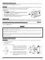
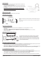
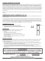
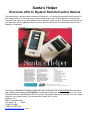
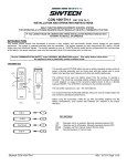
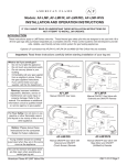
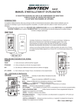
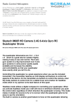
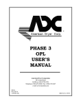
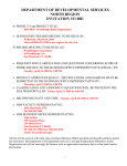
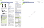
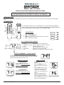
Model: 1001 T/LCD-A
INSTALLATION AND OPERATING INSTRUCTIONS
IF YOU CANNOT READ OR UNDERSTAND THESE INSTALLATION
INSTRUCTIONS DO NOT ATTEMPT TO INSTALL OR OPERATE
INTRODUCTION
This remote control system was developed to provide a safe, reliable and user-friendly remote control system for gas heating appliances.
TRANSMITTER
WALL CLIP
SLOT
ON
BUTTON
ROOM
The transmitter operates on (2) 1.5V AAA batteries. It is recommended that ALKALINE
batteries always be used for this product. Be sure the batteries are installed with the (+)
and (-) ends facing the correct direction, and are fully charged.
TEMP
ON
TIMER
BUTTON
OFF
TIMER
OFF
BUTTON
KEY SETTINGS
SET
1.
2.
3.
4.
SET
BUTTON
BATTERY
COMPARTMENT
FRONT
ON - - - Turns appliance on.
OFF - - Turns appliance off.
TIMER Changes unit from manual mode to timer mode.
SET - - Adjusts timer setting.
ON
1
OFF
2
TIMER
3
SET
4
BACK
LCD - LIQUID CRYSTAL DISPLAY
1.
2.
3.
4.
5.
6.
Display - - - - - - - - - Fahrenheit or Celsius
Flame - - - - - - - - - - Room - - - - - - - - - - Temperature - - - - - Set - - - - - - - - - - - - -
Indicates current room temperature.
Indicates degrees Fahrenheit or Celsius.
Indicates appliance is on.
Indicates remote is in thermo mode.
Appears during manual operation.
Appears when adjusting the desired timer setting.
SETTING ºFAHRENHEIT / ºCELSIUS SCALE
The factory setting for temperature is ºF. To change the displayed
temperature scale, press the ON and OFF keys at the same time.
Follow this same procedure to return to ºF.
MANUAL FUNCTION
ROOM
TEMP
ON OPERATION:
Press the ON key to turn the
appliance on. (The flame icon will
appear on the LCD screen).
ROOM
TEMP
OFF MODE
Skytech 1001T/LCD-A
OFF OPERATION:
Press the OFF key to turn the
appliance off. (The flame icon will
disappear from the LCD screen).
TEMP
TIMER FUNCTION
•
•
•
ON MODE
ROOM
•
•
Press the ON button to start the
appliance.
Press the TIMER button. The
LCD screen will show the word
SET
set.
Press the SET button until the
SET MODE
desired time is reached (15min
- 180min in 15 minute increments). The max setting time is
3 hours.
NOTE: The LCD display will
flash the set time for 6 seconds, then start the countdown.
COUNT DOWN MODE
Press the OFF button to turn off
the timer, and the appliance.
REV 4/15/11 Page 1
TEMPERATURE UPDATING FEATURE
This remote control has a temperature updating feature built into its software. The transmitter reads the room temperature every 2 minutes, then updates the room temperature on the LCD screen.
RECEIVER
Install the 4 AA-size batteries supplied with the unit. It is recommended that ALKALINE batteries always be used for this product. Be
sure the batteries are installed with the (+) and (-) ends facing the correct direction.
Requires 4-AA 1.5V
alkaline batteries
Learning
button
ON
Slide
Switch
LEARN
REMOTE
ON
REMOTE
OFF
OFF
The remote receiver has a 3-position slide switch for selecting the mode of operation
ON/REMOTE/OFF
• ON: will manually turn on appliance.
• REMOTE: will allow use of handheld transmitter. If the system does not respond
to the transmitter on initial use, check the battery positions in the remote. If that
does not work, see the SECURITY CODE section.
• OFF: will disable the remote receiver.
• It is suggested that the slide switch be placed in the OFF position if you will
be away from your home for an extended period of time.
Bat
ter
y
e
cov
d
r sli
es
on/
off
Remote Receiver
INSTALLATION
The remote receiver can be either wall-mounted in a standard plastic switch box (not metal) or placed on or near the fireplace hearth.
Preferably, the remote receiver should be wall-mounted in a plastic switch box, as this will protect its electronic components from the
heat produced by the gas appliance. The remote receiver should be kept away from temperatures exceeding 130º F. Battery life is
also significantly shortened if batteries are exposed to temperatures 130ºF or higher.
Before installation make sure the remote receiver slide switch is in the OFF position. After installation be sure that the slide switch is
moved to the REMOTE position.
WARNING
This remote control system must be installed exactly as outlined in these instructions. Read all instructions completely before attempting installation. Follow instructions carefully during installation. Any modifications of this remote control or any of its components will void the warranty and may pose a fire hazard.
Consult gas appliance manufacturer’s instructions and wiring schematics for proper placement of all wires. All electronic modules
are to be wired to manufacturer’s specifications.
The following wiring diagrams are for illustration purpose only. Follow instructions from manufacturer of gas valve and/or electronic
module for correct wiring procedures. Improper installation of electric components can cause damage to electronic module, gas
valve and remote receiver.
MOUNTING THE REMOTE RECEIVER
WALL MOUNT
When wall mounting the remote receiver, longer wires (not included) are required to connect to the gas valve or electronic module.
These wires must:
• Be at least 18 Gauge (AWG)
• Be no longer than 20’
• Have no splices
Position the cover plate so the word ON is facing up; then, install the remote receiver into the
plastic switch-box using the two long screws
provided. Push the white button over the receiver slide switch.
Skytech 1001T/LCD-A
L
WAL
Receiver
Slide
Button
LEARN
To attach Cover Plate to Receiver Box:
Position the receiver as shown in diagram to
the left with lower tab on cover plate inserted
into groove of receiver (Make sure ADJ hole
and LEARN hole on cover plate properly
aligns with remote receiver). Pull receiver up
and snap into top tab of cover plate.
ON
R
E
M
O
T
E
OFF
Cover Plate
Plastic Switch Box
REV 4/15/11 Page 2
HEARTH MOUNT
•
•
•
The remote receiver can be placed on the fireplace hearth or under the fireplace behind the control access panel.
Use the wires attached to the remote receiver to connect to the gas valve or
the electric module (piggyback connectors have both male & female terminals
for flexibility).
Be sure that the connectors do not touch each other or other bare metal
surfaces; this will cause the appliance to turn on. The connectors may be
wrapped with electrical tape to prevent this.
WIRING INSTRUCTIONS
A qualified electrician should install the remote control system.
WIRING MILLIVOLT VALVES
TERMINAL BLOCK
ON MILLIVOLT
GAS VALVES
TH
TP
TP
•
TH
•
Connect one wire from the remote receiver to the TH terminal on the gas
valve.
Connect the other wire from the remote receiver to the TH/TP terminal on
the gas valve.
THERMOPILE/
PILOT LIGHT
REMOTE
RECEIVER
MILLIVOLT SYSTEM CHECK
•
•
•
•
Ensure that the pilot flame is lit.
Slide the 3-position button on the remote receiver to the ON position. The main gas flame (i.e., the fire) should ignite.
Slide the button to OFF. The main flame should extinguish (the pilot flame will remain on).
Slide the button to REMOTE, then press the ON button on the transmitter to change the system to on. The main
gas flame should ignite.
WIRING ELECTRONIC SPARK IGNITIONS
ELECTRONIC MODULE
TR
TH
110/24VAC
Transformer
neutral wire
24VAC
REMOTE
RECEIVER
hot wire
The remote control receiver can be connected, in series, to a 24VAC
transformer to the TR (transformer) terminal on the ELECTRONIC
MODULE. Connect the hot wire from the 24VAC transformer to either
of the wire terminals on the remote receiver. Connect another wire between the other receiver wire terminal and the TH (thermostat) terminal
on the ELECTRONIC MODULE.
120VAC
ELECTRONIC SPARK SYSTEM CHECK
•
•
•
Slide the 3-position button on the remote receiver to the ON position. The spark electrode should begin sparking to ignite the pilot.
After the pilot flame is lit, the main gas valve should open and the main gas flame should ignite.
Slide the button to OFF. The main gas flame and pilot flame should both extinguish.
Slide the button to REMOTE, then press the ON button on the transmitter to change the system to on. The spark electrode should
begin sparking to ignite the pilot. After the pilot is lit, the main gas valve should open and the main gas flame should ignite.
CP (CHILDPROOF) FEATURE
This remote control includes a childproof feature that allows the user to “lock-out” operations from the Transmitter.
• To activate and de-activate the childproof feature, press and hold the ON button and the TIMER button at the same time for 5 seconds. The letters “CP” will appear in the TEMP frame on the LCD screen when childproof mode is activated.
• “CP” will appear on the LCD screen if any button is pressed while childproof mode is engaged.
• When this mode is engaged, all auto settings go on without interruption (like thermostat). Only manual functions are prevented.
Skytech 1001T/LCD-A
REV 4/15/11 Page 3
LEARNING TRANSMITTER TO RECEIVER
Each transmitter uses a unique security code. It will be necessary to press the LEARN button on the receiver to accept the transmitter
security code upon initial use, if batteries are replaced, or if a replacement transmitter is purchased from your dealer or the factory. In
order for the receiver to accept the transmitter security code, be sure the slide button on the receiver is in the REMOTE position; the
receiver will not LEARN if the slide switch is in the ON or OFF position. The LEARN button in located on the front face of the receiver;
inside the small hole labeled LEARN. Using a small screwdriver or end of a paperclip gently press and release the black LEARN button
inside the hole. When you release the LEARN button the receiver will emit an audible “beep”. After the receiver emits the beep press
the transmitter ON button and release. The receiver will emit several beeps indicating that the transmitter’s code has been accepted
into the receiver.
NOTE: This receiver can hold up to 3 transmitter codes. This is for the times when a second hand held transmitter or a wall transmitter
is required.
COMMUNICATION - SAFETY - TRANSMITTER - (C/S - T/X)
This remote control has a COMMUNICATION –SAFETY function built into its software to ensure the transmitter and receiver are communicating normally.
In all operating modes, the transmitter sends an RF signal every fifteen minutes to the receiver indicating that the transmitter is within
the normal operating range of 20-feet. Should the receiver NOT receive this signal, the receiver will begin a 2 hour countdown. If the
receiver does not receive a signal from the transmitter in 2 hours, the receiver will shut off the appliance. The receiver will then emit a
series of rapid “beeps” for a period of 10 seconds. Then after 10 seconds of rapid beeping, the receiver will continue to emit a single
“beep” every 4 seconds until a transmitter ON, OFF or MODE Button is pressed to reset the receiver.
TRANSMITTER WALL CLIP
The transmitter can be hung on a wall using the clip provided.
• Wood - Drill 1/8’’ pilot holes and install with screws provided.
• Plaster/Wallboard - Drill 1/4’’ holes, then install with the screws provided.
WALL CLIP
SLOT
WALL CLIP
BATTERY LIFE
Life expectancy of the alkaline batteries in the transmitter and receiver
should be at least 12 months. Check and replace all batteries:
• Annually.
• When operating range becomes reduced.
• When transmissions are not received by the remote receiver.
• If the remote receiver batteries measure less than 5.3 volts (all four batteries in combination).
• If the hand held transmitter batteries measure less than 2.5 volts (both
batteries in combination).
BATTERY
COMPARTMENT
TROUBLE SHOOTING
If you encounter problems with your fireplace system, the problem may be with either the fireplace itself or with this remote. Review
the fireplace manufacturer’s operation manual to make sure all connections are properly made. Then check the operation of the
remote in the following manner:
• Make sure all batteries are correctly installed in the transmitter and receiver. Also check if the batteries are fully charged.
• Check batteries in transmitter to make sure contacts are touching (+) and (-) ends of battery. Bend metal contacts in for tighter fit.
• Be sure receiver and transmitter are within 20 to 25-feet operating range.
• Keep receiver from temperatures exceeding 130 degrees F. Battery life will be shortened if exposed to high temperatures.
• If receiver is installed in a tightly enclosed metal surrounding, the operating distance will be shortened.
• Make sure the hand-held transmitter and remote receiver are communicating properly (See LEARNING TRANSMITTER TO RECEIVER section).
FCC REQUIREMENTS
NOTE: THE MANUFACTURER IS NOT RESPONSIBLE FOR ANY RADIO OR TV INTERFERENCE CAUSED BY UNAUTHORIZED MODIFICATIONS TO THIS EQUIPMENT. SUCH MODIFICATIONS COULD VOID THE USER’S AUTHORITY TO OPERATE THE EQUIPMENT.
FOR TECHNICAL SERVICE, CALL:
U.S. INQUIRIES
888/672 - 8929 OR 260/459 - 1703
WEB SITE: www.skytechsystem.com
CANADIAN INQUIRIES
877/472 - 3923
MANUFACTURED EXCLUSIVELY FOR SKYTECH II, INC
Skytech 1001T/LCD-A
REV 4/8/11 Page 4
Limited Lifetime Warranty
SKYTECH II warrants the SKYTECH REMOTE CONTROL SYSTEM for a Limited Lifetime of the original
owner of this system. This warranty is not transferable to another person it is for the original purchaser of the
product. Should any part fail because of defective workmanship or material from the original date of purchase.
SKYTECH II will repair or, at SKYTECH II option, replace the defective parts.
Replacement parts will be available at no charge for the first (5) five years of this warranty, and will be
available at market cost for the Lifetime of the product to that original owner. If SKYTECH II does not have the
parts for an individual model, then a replacement SYSTEM will be provided. At no charge for the first (5) five
years and sold at market cost for the Lifetime of that product to the original owner.
The Owner must provide a bill of sale, cancelled check, or payment record should be kept to verify purchase
date and establish warranty period. Travel, diagnostic cost, service labor to repair the defective SYSTEM, and
freight charges on warranty parts to and from the factory will be the responsibility of the owner. SKYTECH will
not be responsible for labor charges and/or damage incurred in installation, repair, replacement, or for
incidental or consequential damages. Batteries and any damage caused by them are not covered by them are
not covered by this warranty.
This warranty does not cover claims, which do not involve defective workmanship or materials.
Damage to the SYSTEM caused by accident, misuse, abuse, or installation error, whether performed by a
contractor, Service Company, or owner, is not covered by this warranty. Modification of the SKYTECH product
will void this warranty.
IN NO EVENT SHALL SKYTECH BE LIABLE FOR INCIDENTAL AND CONSEQUENTIAL INCLUDING THE IMPLIED
WARRANTIES OF MERCHANTABILITY AND FITNESS, ARE LIMITED TO THE DURATION OF THIS WRITTEN
WARRANTY. THIS WARRANTY SUPERSEDES ALL OTHER ORAL OR WRITTEN WARRANTIES.
Some States do not allow the exclusion or limitation of incidental and consequential damages or limitation on
how long an implied warranty lasts, so the above limitation may not apply to you. This warranty gives you
specific rights and you may have other rights, which vary from state, province, and nation.
How to Obtain Service:
Contact SKYTECH II or your SKYTECH Dealer direct with the following information:
Name, Address, Telephone Number of Owner
Date of Purchase, Proof of Purchase
Model Name, Date Code
Any relevant information or circumstances, e.g., installation, mode of operation when defect was noted.
Warranty claim process will start with all of this information. SKYTECH will reserve the right to physically
inspect the product for defects, by authorized representatives.
Detach at this line for return to: Skytech II 9230 Conservation Way, Fort Wayne, IN 46809 Telephone: (888) 672-8929
Purchase Date:
Model:
Purchased From:
Customer
Name
Date Code:
Date:
Number of Santa’s Helpers
Address
City
Credit Card Number
(Visa and MasterCard Only)
State/Prov.
Zip/Postal Code
Expiring Date
See other side for a special offer for all Remote control Customers
Santa’s Helper
Exclusive offer to Skytech Remote Control Owners
This special offer is only provided to customers of Skytech II, Inc. that have purchased a remote control for
their Hearth Product. This remote control system can be used for any 110Volt appliance, but perfect your
Christmas Tree Lights or any other appliance that is difficult to reach or plug in. Simply plug the receiver into
your wall outlet and your appliance into the receiver, push the ON button on the transmitter and you are in
business. It’s that easy.
The list price of $29.95 for the Santa’s Helper has been cut almost in half to $15.00 USD for this exclusive
offer. Shipping and handling of $5.00 $USD should be added. Send your check, money order or your Visa /
MasterCard number, with Expiration Date to our office, along with the warranty information from your remote
control for your Hearth Product. You can send this via mail, fax, or e-mail.
Skytech II, Inc.
9230 Conservation Way
Fort Wayne, IN
46809
1 (888) 672-8929
1 (888) 672-8024 Fax
[email protected] e-mail