1
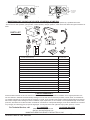
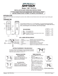
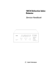
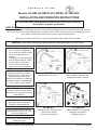
AMERICAN
FLAME
A F
!
Models: AF-LMF, AF-LMF/R, AF-LMF/RD, AF-LMF-RVS
INSTALLATION AND OPERATION INSTRUCTIONS
IF YOU CANNOT READ OR UNDERSTAND THESE INSTALLATION INSTRUCTIONS DO
NOT ATTEMPT TO INSTALL OR OPERATE
INTRODUCTION
These instructions apply to LMFSeries valve kits: These Natural gas safety pilot kits are designed to be used with 18 to
30-inch gas logs sets purchased separately as a complete valve kit. These control systems were developed to provide
safe, reliable, user-friendly remote control system for gas heating appliances.
Optional LP conversion kits AFLPK-18, AFLPK-24 and #685-25 Pilot Orifice Kits are available.
Important: Read these instructions carefully before starting installation of your log set.
What to do if you smell gas?
• Do not try to light the appliance
• Do not touch any electrical switch
• Do not use any phone in your
building
• Immediately call your gas supplier
from a neighbor’s phone. Follow
the gas suppliers instructions.
• If you cannot reach your gas
supplier, call the fire department.
Warning: Improper installation,
adjustment, alteration, service or
maintenance can cause injury or
property damage. Refer to this
manual. For assistance or additional
information consult a qualified installer, service agency or gas supplier.
AF-LMF
Manual ON/OFF Gas Valve
AF-LMF/R
Manual ON/OFF Gas Valve with
Solenoid and ON/OFF Remote
Stainless Flex Line to Burner
For Your Safety: Do not store or use
gasoline or other flammable vapors
and liquids in the vicinity of this or any
other appliance.
Aluminum Pilot tube
with Thermocouple & Pilot assembly
Transmitter
ON/OFF
H/M/L
Notice: Please leave these
instructions for the consumer.
Retain for future reference.
Young children should be carefully
supervised when they are in the same
room as the appliance.
Damper Clamp
Receiver Shield
Receiver
OFF
AF-LMF/RD
Manual ON/OFF Gas Valve with
Solenoid and ON/OFF
(Touch Screen) Remote
REMOTE
AF-LMF/RVS
Manual ON/OFF Gas Valve with
Step Motor and ON/OFF
(Hi/Med/Lo) Remote
Be sure flue damper and glass doors
are fully open when operating any
vented gas log set.
American Flame AF-LMF Valve Kits
REV 1-31-12 Page 1
WARNING
This control system must be installed exactly as outlined in these instructions. Read all instructions completely before attempting
installation. Follow instructions carefully during installation. Any modifications of this control or any of its components will void the
warranty and may pose a fire hazard.
These instructions must be used as a supplement to the instructions supplied with the gas log set. Follow the gas log instructions
supplied by the manufacturers on the placement of the burner pan, log basket grate, burner media (sand or vermiculite), ember
material and the log placement. Please follow these instructions on the connection of the inlet line to the gas valve and then to the
burner pan assembly.
If your fireplace installation has glass doors, only operate the fireplace with glass doors in the fully open position.
INSTALLATION: VALVE KIT WITH PRE-EXISTING LOG SET
1. Make sure all gas flow is completely turned off to the gas log set. Make sure you have a certified and approved shut-off within
6-feet of the fireplace, or whatever the local inspection authority requires.
2. Remove all logs and basket grate and set aside.
3. Disconnect the 3/8” Flared fitting at the existing manual valve from the inlet gas supply.
4. Remove existing manual valve and fittings on the burner pan.
5. Locate a position on the back of the burner pan about 4-inches from the right or left side of the burner pan. (Figure #1 & #2)
6. Mount pilot assembly to burner pan as shown in Figure # 3. Note this pilot bracket clips on the burner pan and holds the pilot at
a 45-degree position onto the pan with no screws required. A screw can be added to secure the pilot assembly if needed. Bend
1/4” stainless pilot tubing from pilot assembly until the bottom of the pilot bracket is resting against the pan. (This will hold the pilot
at the 45 degree position) then connect pilot fitting to valve. (Use caution when bending pilot tubing not to kink the tubing or
locate the tubing in or over the burner pan).
7. Locate the valve kit in the right or left front corner of the firebox as far forward as possible (See Figure #4).
8. Bend inlet gas supply line and connect the 3/8” flare fitting to gas valve 3/8” inlet connector (Fitting with printed label) (Use caution
not to kink the line when bending).
9. Bend 12” stainless flex line and connect to valve outlet then connect other end to 3/8” flare fitting on burner pan (Caution do not
let gas inlet line to the valve kit or gas outlet line from the valve kit be placed in or over the burner pan).
10. Turn on gas supply and check all connections for leaks using soapy water solution.
11. Follow valve pilot lighting instructions. After pilot is lit, check pilot fittings for leaks.
12. Reinstall basket grate and logs.
13. Install Damper stop (supplied with this valve kit) (This allows damper to remain slightly open to allow the pilot to vent)
NOTE: On all PROPANE installations it is recommended that an inlet pressure regulator be used.
INSTALLATION: VALVE KIT WITH NEW LOG SET
1. Make sure all gas flow is completely turned off to the fireplace. Make sure you have a certified and approved shut-off within 6-feet
of the fireplace, or what ever the local inspection authority requires.
2. Follow the instructions supplied with the log set to locate the burner pan. Using the fittings, orifice and gas supply line that came
with the log set, connect the line to the inlet gas supply.
3. Locate a position on the back of the burner pan about 4-inches from the right or left side of the burner pan. Note: (Figure #1 & #2)
4. Mount pilot assembly to burner pan as shown in (Figure #3). Note this pilot bracket clips on the burner pan and holds the pilot at a
45-degree position onto the pan and no screws required. Note: A screw can be added to secure the pilot assembly if needed. Bend
1/4” stainless pilot tubing from pilot assembly until the bottom of the pilot bracket is resting against the pan. (This will hold the pilot
at the 45 degree position) then connect pilot fitting to valve. (Use caution when bending pilot tubing not to kink the tubing or
locate the tubing in or over the burner pan)
5. Locate the valve kit in the right or left front corner of the firebox as far forward as possible (See Figure #4)
6. Bend inlet gas supply line and connect the 3/8” flare fitting to gas valve 3/8” inlet connector (Fitting with printed label) (Use caution not to kink the line when bending).
7. Bend 12” stainless flex line and connect to valve outlet then connect other end to 3/8” flare fitting on burner pan (Caution do not let
gas inlet line to the valve kit or gas outlet line from the valve kit be placed in or over the burner pan).
8. Turn on gas supply and check all connections for leaks using soapy water solution.
9. Follow valve pilot lighting instructions. After pilot is lit check pilot fittings for leaks.
10. Follow the instructions supplied with the log set to install ember material, basket grate and logs.
11. Install Damper stop (supplied with this valve kit) (This allows damper to remain slightly open to allow the pilot to vent).
NOTE: On all PROPANE installations it is recommended that an inlet pressure regulator be used.
American Flame AF-LMF Valve Kits
REV 1-31-12 Page 2
Pilot monting location
Optional pilot mounting location
4.00”
4.0”
4.0”
Figure #1
Burner Pan
Figure #2
Basket Grate
Optional Valve mounting location
Burner Pan
AFLMF Valve Kit
Basket Grate
Burner Pan
2.0” Min.
Figure #3
2.0” Min.
Figure #4
2.0” Min.
2.0” Min.
Optional Valve mounting location
AFLMF Valve Kit
CONNECTING THE REMOTE CONTROL ON AF-LMF/R & AF-LMF/RD & AF-LMF-RVS VALVE KITS
1. The remote control receiver is to be placed next to the valve kit, away from the fire (Note: Figure #5).
2. Remove receiver shield and battery cover then install (4) AA alkaline batteries. Reinstall receiver shield.
3. Connect the red and black wires from the ON/OFF latching solenoid on the valve to the red and black wires from the remote receiver. If installing the AF-LMF-RVS connect the 4-pin connector from the step motor to the remote receiver (Figure #6).
4. Refer to the instructions supplied with the remote control for operation of the remote control.
Basket Grate
Burner Pan
Flat 4 Wire with
4 pin Male
Connector
Flat 4 Wire with
4 pin Female
Connector
Flat 4 Wire with
4 pin Female
Connector
Flat 4 Wire with
4 pin Male
Connector
RCAF-LMF
Remote Control
Receiver
RCAF-LMF
Remote Control
Receiver
AFLMF Valve Kit
AFLMF Valve Kit
Figure #5
LIGHTING & SHUT OFF PROCEDURES
Receiver Back
AFLMF
Figure #6
WARNING: IF YOU DO NOT FOLLOW THESE INSTRUCTIONS EXACTLY, A FIRE OR EXPLOSION
MAY RESULT CAUSING PROPERTY DAMAGE, PERSONAL INJURY OR LOSS OF LIFE.
•
•
•
•
•
This product has a standing pilot, which must be lit by hand. When lighting the pilot, follow these instructions exactly.
This product should be installed including provisions for combustion and ventilation air, must conform with local codes or, in the
absence of local codes, to the National Fuel Gas Code, ANSI Z223 latest addition.
This product must be on a gas supply line that is less than 1/2 psi. and with an individual manual shut off.
Never operate this new system with the glass fireplace enclosures (doors) in the closed position.
Connecting 110-volt electrical power to this product will cause damage and will void warranty.
PILOT GAS AND LIGHTING PROCEDURE
1. Turn the gas control knob counterclockwise to the PILOT position, push the gas control knob IN and HOLD in position. This will
open the pilot valve and allows gas to flow to the pilot burner.
2. Light the pilot burner while holding the gas control knob in until a strong pilot flame is present. (Approximately 60-seconds)
3. Release the gas control knob and verify the pilot flame remains lit.
4. Turn the gas control knob counter clockwise to the ON position, The main burner valve will open and the main burner will ignite,
SHUT OFF PROCEDURE
1. To shut OFF the main burner while leaving the pilot ON, turn the gas control knob clockwise to the PILOT position. This action will
close the main gas flow.
2. To shut OFF the main burner and pilot, turn the gas control knob clockwise to the OFF position. This action will close the main gas
valve and disengages the safety pilot valve. However the power unit must drop out before the lighting sequence can begin again.
This may take as long as 3 minutes.
3. To relight the pilot, follow the steps in the Pilot Gas and Lighting Procedure section.
American Flame AF-LMF Valve Kits
REV 1-31-12 Page 3
Back Inlet
Removable Plug
For Solenoid or
Step Motor
Back Outlet
Pilot connection
Thermocouple
Connection
Pilot Adjustment
Gas Control Knob
Front
Back
MAINTENANCE OF YOUR AF-LMF, AF-LMF/R, AF-LMF/RD & AF-LMF-RVS
- Your system should be checked once a year (At the start of the heating season) for proper operation by a qualified serviceman.
- Items to check: Valve operation, pilot operation, switch operation, damper operation, visual check of the burner and gas connections for
leaks.
1 2 3 4
(Attached to Valve)
8
5
7
ON
PARTS LIST
6
9
11
10
LEARN
ON
OFF
14
12
REMOTE
13
OFF
OFF
12V
17
16
15
ON
AA A
A
AA
AA
AAAAA
A
AAA A
AA
1. AF-LMF Valve Assembly
SS-1-010-1000
2. AF-LMF /R Valve Assembly
SS-2-010-1000
3. AF-LMF /RD Valve Assembly
SS-2-101-1000
4. AF-LMF /RVS Valve Assembly
SS-2-080-1002
5. 10-inch Stainless Flex Connector
SS-3-093-1000
6. Damper Stop
SS-3-170-1001
7. Pilot Assembly
SS-3-091-1000
8. 3/8” Flare x 3/8” NPT Connector
SS-3-093-1000
9. Receiver Shield
SS-3-170-1000
10. 6-volt DC Receiver (For R & RD Models)
SS-3-030-1003
11. 6-volt DC Receiver (For RVS Model)
SS-3-030-1001
12. ON/OFF Transmitter (Con1001) R Model
SS-3-020-1000
13. ON/OFF Transmitter (SKY5001) RD Model
SS-3-020-1001
14. ON/OFF Hi/Med/Lo Transmitter (RCAF-1035) for RVS Model
SS-3-020-1003
15. 12-volt Battery (1 Required for R & RVS Model Transmitters)
SS-1-060-1000
16. AA Battery (4 Required for R & RD receivers)
SS-1-060-1001
17. AAA Battery (4 Required for RD Transmitter)
SS-1-060-1002
LIMITED WARRANTY
American Flame warrants the AF-LMF Valve Kit for 12 months from the date of purchase or installation to the original purchaser to be
free from defects in materials and workmanship. Damage to the AF-LMF Valve Kit caused by accident, misuse, abuse, or installation error, whether preformed by a contractor, Service Company, or owner, is not covered by this warranty. American Flame will not be responsible for labor charges and/or damage incurred in installation, repair, replacement, or for incidental or consequential damage. Some states,
provinces, and nations do not allow exclusion or limitations of incidental or consequential damages, so the above limitations or exclusions
may not apply. This warranty gives you specific legal rights. You may also have other rights that vary by state, province, or nation.
For Technical Service, call:
U.S. INQUIRIES
(888) 672-8929 or (260) 459-1703
Web site: www.skytechsystem.com
CANADIAN INQUIRIES
(877) 472-3923
MANUFACTURED EXCLUSIVELY FOR SKYTECH II, INC
American Flame AF-LMF Valve Kits
REV 1-31-12 Page 4