1
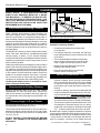
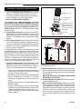
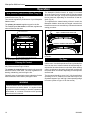
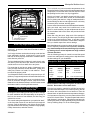
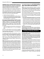
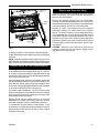
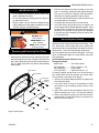
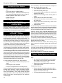
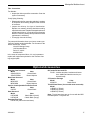
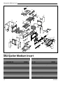
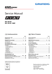
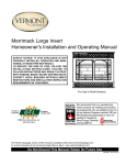
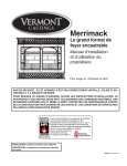
Montpelier Medium Insert
Homeowner’s Installation and Operating Manual
For Use in North America
SAFETY NOTICE: IF THIS APPLIANCE IS NOT PROPERLY INSTALLED, OPERATED AND MAINTAINED, A HOUSE FIRE MAY RESULT.
TO REDUCE THE RISK OF FIRE, FOLLOW THE INSTALLATION 4403
INSTRUCTIONS. FAILURE TO
FOLLOW INSTRUCTIONS MAY RESULT IN PROPERTY DAMAGE,
BODILY INJURY
Montpelier
cover OR EVEN
DEATH. CONTACT LOCAL BUILDING OFFICIALS ABOUT RESTRICTIONS
AND
INSTALLATION
1/08
INSPECTION REQUIREMENTS IN YOUR AREA.
259-S-13-2
The French language version of this manual is available online:www.vermontcastings.com
La version française de ce manuel est disponible en ligne : www.vermontcastings.com
Do Not Discard This Manual: Retain for Future Use
30004403 0515 Rev. 17
Montpelier Medium Insert
Introduction
Thank you for purchasing a Vermont Castings Montpelier Medium Insert, an efficient wood stove carefully engineered
to bring you the latest in wood combustion principles and modern foundry technology.
This stove transforms a traditional masonry fireplace into a powerful heater. You can count on years of comfortable heating and pleasurable fire-viewing if you operate and maintain it according to the directions in this Owner’s Guide.
This Insert has been tested and listed by OMNI-Test Laboratories of Portland, Oregon to UL1482-1996(R2006) for the
United States and ULC S628-93 for Canada. This Insert is listed to, and in compliance with, the standards set forth by
the Federal Environmental Protection Agency, 40 CFR Part 60.532(b), as stated on the permanent label attached to the
stove.
This manual describes the installation and operation of this Insert. This heater meets the U.S. Environmental Protection
Agency’s emission limits for wood heaters sold after May 15, 2015. Under specific test conditions this heater has been
shown to deliver heat at a rate ranging from 10,100 to 27,550 BTU/hr.
For more complete details on stove performance and specifications, please refer to Page 3.
The Montpelier Medium Insert is designed, tested and listed for burning wood. Do not burn other fuels.
Installation or service of the Montpelier Medium Insert should be performed only by a qualified installer, preferably NFI
or WETT (Canada) certified.
Please read entire manual before you install and use your new Insert.
Failure to follow these instructions may result in property damage, bodily injury or even death.
Save These Instructions for Future Reference
Table of Contents
Specifications.......................................................... 3
Installation............................................................... 4
Smoke Alarm/Safety Tip........................................ 10
Operation............................................................... 11
Maintenance.......................................................... 14
Optional Accessories............................................. 17
Replacement Parts................................................ 18
Warranty................................................................ 20
Proposition 65 Warning: Fuels used in gas, woodburning or oil fired appliances, and the products of
combustion of such fuels, contain chemicals known to
the State of California to cause cancer, birth defects
and other reproductive harm.
California Health & Safety Code Sec. 25249.6
2
The Montpelier Medium Insert is designed,
tested and listed for burning wood. Do not burn
other fuels.
The Montpelier Medium Insert is not listed for
mobile home installations.
Failure to follow these instructions may result in
property damage, bodily injury or even death.
WARNING
This stove has not been tested with an unvented
gas log set. To reduce the risk of fire or injury,
do not install an unvented gas log set into this
fireplace.
30004403
Montpelier Medium Insert
Specifications
Montpelier Medium Insert
EPA Emissions Rating........................................3.0 g/hr
Efficiency, HHV*......................................................69%
Range of heat output**............. 10,100 - 27,550 BTU/hr
Maximum heat output***..........................40,000 BTU/hr
Area heated****........................................... 1,500 sq. ft.
Size of wood splits.....................18"-22" (460 - 560 mm)
Fuel Capacity......................................... 30lbs. (13.5kg)
Loading...................................................................Front
Flue size...................................................... 6" (150mm)
Fireplace Insert weight........................ 335 lbs. (152 kg)
Primary Air Control............................................. Manual
Glass panel.......................... High-temperature ceramic
Flue exit position...................................................... Top
Blower rating...............................150 cfm. (115V, 60Hz)
Power Cord Length................... 6 foot useable installed
*Efficiency determined by CSA B415.10.
**Under specific test conditions used during EPA emissions
standard testing.
***This value can vary depending on how the unit is operated, and the type and moisture content of the fuel used.
The figure shown is based on maximum fuel consumption
obtained under laboratory conditions and with average
efficiencies.
****These values are based on operation in building-code
conforming homes under typical winter climate conditions
in New England. If your home is of nonstandard construction (e.g. unusually well insulated, not insulated, built
under ground, etc.) or if you live in a more severe or more
temperate climate, these figures may not apply. Since so
many variables affect performance, consult your Vermont
Castings’ Authorized Dealer to determine realistic expectations for your home.
26³⁄₄” (680 mm)
14¹⁄₄” (362 mm)
22¹⁄₄” (564 mm)
11¹⁄₂”
(292 mm)
30¹⁄₂” (774 mm)
17¹⁄₄” (434 mm)
28³⁄₄” (730 mm)
22¹⁄₄”
(565 mm)
21¹⁄₂”
(548 mm)
Fig. 1 Montpelier Medium Insert dimensions.
3
30004403
4403
Montpelier dims
1/08
Montpelier Medium Insert
Installation
SAFETY NOTICE: IF YOUR MONTPELIER MEDIUM
INSERT IS NOT PROPERLY INSTALLED, A HOUSE
FIRE MAY RESULT. TO REDUCE THE RISK OF FIRE,
FOLLOW THE INSTALLATION INSTRUCTIONS. CONTACT LOCAL BUILDING OR FIRE OFFICIALS ABOUT
RESTRICTIONS AND INSTALLATION INSPECTION
REQUIREMENTS IN YOUR AREA.
0 To 10’
2’ Min.
3’
Min.
0 To 10’
2’ Min.
3’
Min.
Requirements for Existing Fireplaces
The Montpelier Medium Insert is listed for installation
within a properly built masonry or heat circulating, masonry-type fireplace that is constructed in accordance
with the requirements of recognized building codes. A
heat-circulating masonry-type fireplace must conform to
building code standards for masonry fireplaces, and must
consist of a factory-built metal firebox with air circulation
pathways that are surrounded by masonry materials. Air
circulation pathways must not be blocked by the insert or
surround panels.
The fireplace and chimney must be clean and structurally
sound. Have them inspected by a qualified professional
chimney sweep, a mason, or your Vermont Castings’
Authorized Dealer before the Montpelier Medium Insert is
installed. Any deterioration (cracks, loose mortar or loose
bricks) must be repaired.
Codes may permit removal of the damper in order to make a
positive vent connection between the firebox and the chimney. However, the fireplace should not be modified in any
way without first checking with your local building inspector
or fire marshal. Provision should be made to restore the
fireplace to its original condition if the insert is removed.
Do not remove bricks or mortar that may jeopardize the
compliance of the fireplace with local building codes.
The Montpelier Medium Insert is not listed for installation in factory-built fireplaces.
Requirements for Existing Chimneys
Chimney requirements differ for the U.S. and Canada.
Specifications for each are listed below. Connect the
insert to the chimney in accordance with local codes and
the requirements of the listing agency as specified in this
manual.
Chimney Height / U.S. and Canada
Chimney height should be no less than 15’ (4.5 m) above
the hearth and no more than 35’ (10.5 m).
The chimney should extend at least 3’ (914 mm) above the
highest point where it passes through a roof, and at least
2’ (610 mm) higher than any portion of a building within
10’ (3 m). (Fig. 2)
DO NOT CONNECT YOUR MONTPELIER MEDIUM
INSERT TO A CHIMNEY FLUE SERVING ANOTHER
APPLIANCE.
4
Reference
Point
AC617
Fig. 2 The 2’-3’-10’ rule for chimneys.
U.S.
AC617
RLTSKC8
(ANSI/NFPA
211,
2/11/98
In the U.S.
1988), when installed in a masonry fireplace:
• A connector must extend from the flue collar to the flue liner.
• If a stainless steel liner is not used, the connector
must extend at least four (4) feet from the flue collar
of the insert.*
• The cross sectional area of the flue must be less than or equal to three times the area of the flue collar. If larger, the chimney must be re-lined.
• Means must be provided to prevent room air passing to the chimney cavity.
• Provision must be made for removal of the insert to clean the chimney flue.
General Considerations / U.S.
• While not required in most jurisdictions in the U.S.,
Vermont Castings Group strongly recommends
that a full stainless steel chimney liner be installed
for the insert to the chimney top to increase overall
performance and to ease and reduce yearly maintenance.
• A masonry chimney must be well-constructed and
must meet minimum code requirements. The chimney flue should have a code-approved liner made of
masonry or pre-cast refractory tiles, straight or flexible stainless steel pipe, or a poured-in-place liner.
An unlined chimney must be relined professionally.
• The chimney must have a nominal flue size of 6" (152
mm) diameter or 28 square inches (181 cm2) but no
greater than 3 times larger or 85 square inches (548
cm2). A chimney larger than this must be re-lined.
Be aware that a chimney originally designed for fireplace
use may perform differently when used to vent an air-controlled appliance such as your Montpelier Medium Insert
- even if the flue is less than 3 times larger than the flue
collar. For example, a chimney on an outside wall may
* This requirement is in addition to those specified in ANSI/NFPA211.
30004403
Montpelier Medium Insert
not heat up enough to sustain an adequate draft. Such a
flue can often be improved if it is relined to reduce its size
and/or insulated to keep it warmer.
• A positive flue connection must be made between
the Insert and the first masonry tile or prefabricated
metal chimney section. A positive flue connection
consists of a plate that seals or replaces the fireplace
damper and a section of chimney connector that
passes through the plate into the chimney.
• The chimney connector must be a minimum equivalent to a 6" (152 mm) diameter opening and must be
24 gauge or heavier stainless steel. The connector
must extend four (4) feet measured from the collar
of the insert.
Chimney Connection systems are available from a variety
of manufacturers. Your Vermont Castings dealer can recommend a system that will best meet the requirements of
your particular installation.
Sealing Requirements / U.S.
• The chimney must be sealed off from room air, ei•
ther by a plate at the damper level or by sealing the
fireplace opening.
Unused openings to the flue must be sealed with masonry to the thickness of the chimney wall. Openings
sealed with pie plates or wallpaper are a hazard. In
the event of a chimney fire, flames and smoke may
be forced from the openings.
Canada
In Canada (CAN/CSA-B365-M91, Section 5), whether
installed in a masonry or factory built fireplace:
• This fireplace insert must be installed with a continuous chimney liner of 6" (152 mm) diameter extending
from the fireplace insert to the top of the chimney.
The chimney liner must conform to the Class 3
requirements of CAN/ULC-S635, Standard for Lining Systems for Existing Masonry or Factory-Built
Chimneys and Vents, or CAN/ULC-S640, Standard
for Lining Systems for New Masonry Chimneys.
• The opening of the fireplace around the insert must
be sealed to prevent room air passing to the fireplace
cavity.
• Existing air-circulation chambers in a fireplace with
a steel liner may not be blocked.
• Provision must be made for removal of the insert to
clean the chimney flue.
• The existing fireplace damper (if any) should be
locked in the open position.
30004403
• A permanent metal warning label must be affixed to
the back of the fireplace stating the fireplace may
have been altered to accommodate the insert, and
may be unsafe to use as a conventional fireplace. (A
Fireplace Modification Tag is included in the hardware
bag inside the Montpelier Medium Insert.)
Minimum Fireplace Dimensions
The Montpelier Medium Insert will fit most fireplaces. To
confirm that it will fit yours, measure the lintel depth, plus
the height, width, and depth of your fireplace and hearth.
Compare them to the measurements in the accompanying chart. If you choose to install a new hearth over an
existing fireplace hearth, be sure to take its thickness into
consideration when measuring both front and back height
of the fireplace and clearances to any existing trims and
mantels.
The unit can be installed virtually flush with the fireplace
opening or it can extend 3" (76 mm) onto the hearth using
the optional 3" Hearth Extension Kit. Figure 3 gives minimum and maximum dimensions for fireplaces which will
accommodate the Montpelier Medium Insert in the flush
mount configuration and using the optional extension kit.
NOTE: The clearance between the Montpelier Medium
Insert and the mantel, top trim and side trim cannot be
reduced by installing shields.
Another requirement to consider is the clearance for movable
items such as tables, bookcases, rugs, furnishings, and your
woodbox. All combustible materials of this type should be
a minimum of 48" (1220 mm) from the front surface of the
Montpelier Medium Insert. Be sure that family members
are aware of this requirement as well, so they too will keep
objects a safe distance from the Montpelier Medium Insert.
5
Montpelier Medium Insert
A
B
B
C
H
Measure side trim
clearance from here
D,J
C
E
FP1084
A,I
Fireplace Minimums
Flush Mount
3" Extended
Mount
FP1084
A. Width at Face winterwarm
27" (686 mm)
1
B. Width at Dimension
‘C’ 22
⁄2" (572 mm)
221⁄2" (572 mm)
fireplace
minimum
dimensions
1
1
⁄
2" (445 mm) 14 ⁄2" (368 mm)
C. Depth117
3/01
1
D. Height at Face
21 ⁄2" (546 mm) 211⁄2" (546 mm)
E. Height at Dimension ‘C’ 211⁄2" (546 mm) 211⁄2" (546 mm)
Fireplace Maximums
H.Lintel depth
81⁄2" (216 mm)
2
I.Width 411⁄2" (1054 mm)
J.Height2281⁄2" (724 mm)
1. The minimum depth must be maintained from the floor of the fireplace
to a height of 211⁄2" (540 mm)
2. Though the Montpelier Medium Insert will fit into larger fireplaces,
the decorative optional Vermont Castings Group Surround Panels will
not completely cover the fireplace opening if these dimensions are
exceeded. Custom made trim pieces may be used.
Fig. 3 Use these measurements to confirm that the Montpelier
Medium Insert will fit into your masonry fireplace.
Clearance Requirements
After confirming that your fireplace is the right size, check
the clearance to combustibles. First mark with tape the exact
center of your fireplace opening on the hearth. Measure
the side clearance from this point. Measure the top trim
and/or mantel clearances from the finished hearth surface.
Measure the front clearance (to furnishings, etc.) from the
fireplace face. (Fig. 4)
Hearth Requirements
In some fireplaces, the hearth in front of the fireplace opening is brick, stone, slate, or some other non-combustible
material that is in direct contact with concrete poured over
earth. These are the only hearths that are considered
noncombustible. In other fireplaces, the brick or concrete
hearth in front of the fireplace opening is supported by
heavy wooden framing. Because neither brick nor concrete
has good insulating properties, heat radiated by the fire will
pass downward through the hearth to the wooden framing.
Such hearths are considered combustible.
6
FP1085
D,J
E
C
X
Fireplace Clearances
3" Extended
Flush Mount
Mount
A. Mantel
471⁄2" (1207 mm) 441⁄2" (1130 mm)
B. Top Trim (11⁄2")471⁄2" (1207 mm) 361⁄2" (927 mm)
FP1085
C. Side Trim*
21" (533 mm)
21" (533 mm)
WinterWarm
* Where side trim extends
more than 11⁄2" (38 mm) from the fireplace
clearances
facing, the side clearance must be no less than 261⁄2" (673 mm); this
is also the required side 3/01
wall clearance.
Measure the side clearance (C) from the exact center of your fireplace
opening on the hearth (X). Measure the top trim (B) and/or mantel
clearances (A) from the finished hearth surface. Measure the front
clearance (to furnishings, etc.) from the fireplace face.
Fig. 4 Observe these clearances to combustible trim.
Unless the fireplace and hearth are constructed over a
completely non-combustible surface (such as unpainted
concrete over dirt), a thermal floor protector must be used
in front of and to the sides of the door as protection against
spilled coals and embers and heat radiated from the front
of the insert. Floor protectors must extend at least 8" (203
mm) from the side of the insert, making the protector 443⁄4"
(1137 mm) wide.
In addition, the floor protector must extend from the front
door opening a minimum of 16" (406 mm) in the United
States and 18" (457 mm) in Canada. (Fig. 5)
The approved construction of a floor protector calls for a
minimum of 24 gauge galvanized sheet metal or equivalent, and the equivalent of 1.25" (32 mm) of a material with
k-value of 0.84 or less.
Custom-made floor protectors may be used if they offer the
same protection. Millboard has a standard k value of 0.84
and thus 11⁄4" (32 mm) of this material is adequate thermal
protection. Custom-built floor protectors must have a k value
equal to, or less than 0.84, meaning that heat will transfer
at the same rate or more slowly than the tested standard.
How to Determine if Alternate Floor
Protection Materials are Acceptable
All floor protection must be noncombustible (i.e. metals,
brick, stone, mineral fiber boards, etc.). Any organic materials (i.e. plastics, wood paper products, etc.) are combustible and must not be used. The floor protection specified
30004403
Montpelier Medium Insert
EXAMPLE: The specified floor protector should be 11⁄4"
thick material with k-factor of 0.84. The proposed alternate
is 4" brick with an r-factor of 0.2 over 1⁄4" mineral board with
a k-factor of 0.29
B
B
A
C
United States
Canada
A. 18"* (460 mm) 18" (460 mm)
B. 8" (203 mm) 8"
(203 mm)
C.443⁄4" (1137 mm)
443⁄4" (1137 mm)
FP1095
Typically, thermal protection with
the protection
above dimensions will be rehearth
quired. The equivalent of 1.25"2/08
(32 mm)
djt of a material with a k-value
0.84 (or a total R-value of 1.49) is necessary.
If the insert is elevated 81⁄2" (216 mm) or more above a combustible
hearth, thermal protection is not needed. However, spark and ember
protection is still necessary.
*If the insert is elevated 3" (76 mm) or more, with the optional hearth
extension, this dimension may be reduced to 16" (406 mm) (US only)
beyond which no thermal protection is necessary.
FP1095
Step a: Use formula above to convert specification to Rvalue: R = 1 x T = 1 x 1.25 = 1.49
k
0.84
Step b: Calculate R of proposed system.
4" brick of r = 0.2, therefore:
Rbrick = 0.2 x 4 = 0.8
1/8" mineral board of k = 0.29, therefore
1
Rmineralboard =
x 0.25 = 0.431
0.29
Rtotal = Rbrick + Rmineralboard = 0.8 + 0.431 = 1.66
Step c: Compare proposed system Rtotal of 1.66 to specified R of 1.49. Since proposed system Rtotal is greater
than required, the system is acceptable.
Definitions
(ft2)(hr)(°F)
Btu
R=
K = (Btu)(ft)
(ft2)(hr)(°F)
k=
r=
(Btu)(in)
= K x 12
(ft2)(hr)(°F)
(ft2)(hr)(°F) 1
=
(Btu)(in)
k
Optional Surround Packages
Custom-made surround panels may be made from any
noncombustible material.
Fig. 5 Unless your fireplace and hearth are constructed over a
dirt floor (or unpainted concrete over dirt), you must use a floor
protector that satisfies the above requirements.
Vermont Castings Group offers both steel and cast iron
Surround panel kits, each in two sizes.
includes some form of thermal designation such as R-value
(thermal resistance) or k-factor (thermal conductivity).
Georgian Cast Surround.......................Enclosure Area
30DVSGTKCB,
30DVSGTKB.......................301⁄4" x 41 (768 x 1041 mm)
Procedure:
1. Convert specifications to R-value:
i. R-value given - no conversion needed.
ii. k-factor is given with a required thickness (T) in
inches: R = 1 x T
k
iii. K-factor is given with a required thickness (T) in
inches: R = 1
xT
K x 12
iv. r-factor is given with a required thickness (T) in
inches: R = r x T
2. Determine the R-value of the proposed alternate floor
protector:
i. Use the formula in Step 1 to convert values not expressed as R.
ii. For multiple layers, add R-values of each layer to
determine overall R-value.
3. If the overall R-value of the system is greater than the
R-value of the specified floor protector, the alternate is
acceptable.
30004403
Mead Cast Surround:
MEAD3CB....................281⁄4" x 4111⁄16" (718 x 1059 mm)
Caprice Cast Adjustable Profile Surround:
CAPCB.................................. 25" x 35" (635 x 889 mm )
Steel Surround:
LHE30SSB......................... 27" x 381⁄4" (686 X 972 mm)
LHE30SLB..........................281⁄4" x 41" (718 x 1041 mm)
7
Montpelier Medium Insert
Installing the Montpelier Medium Insert
1. Remove or Disable the Fireplace Damper. If codes allow, remove the damper. Many dampers can be removed
simply by removing a cotter pin and/or a set screw.
If it is not permissible or possible to remove the damper,
secure the damper in the fully open position.
~ NOTE: CANADIAN INSTALLATIONS ~
In accordance with CAN/CSA B365-M91, you must
permanently secure the Fireplace Modification Tag to
the rear of the fireplace cavity if you have modified the
fireplace in any way to accommodate installation of a
fireplace insert. This tag is in the hardware bag included
with your Insert.
2. Install the Floor Protector. Make sure the floor protector
satisfies the requirements discussed on Page 6. The
finished height of the floor protector or raised hearth
needs to be considered before installing the venting
system.
3. Flue collar orientation: The flue collar may be oriented
in the vertical position or rotated 180 degrees on the top
of the stove resulting in a 26 degree backward angle. If
possible, determine beforehand which orientation will
work best for your application.
In most applications, cleaning of the chimney system will
be easiest from the top (chimney cap) down. If this is the
planned method for your application, the center iron pull
down handle on the flue collar serves as protection to keep
prevent a chimney brush from damaging the baffle inside
the stove. If cleaning can only take place from inside the
home, the center bar may be cut out of the flue collar using
a hack saw or reciprocating metal cutting saw.
4. Install the venting system: Again, depending on your
application it may be easiest to install the connector or
stainless steel flue liner in the chimney first. Refer to
Figure 6 for the components of the venting system.
• Carefully remove the fiber baffle by first removing the
front air tube. If necessary, removing the remaining
air tubes will allow easier access.
• Remove the iron flue collar from the stove and fasten
either the adapter pipe or flue liner to it by drilling
three holes using the holes in the iron collar as a
guide.
• Secure the flexible pipe to the pipe adaptor using
the same method.
• Install the connector pipe or liner so that the height
measured from the finished hearth surface to the
center bar of the flue collar is 19" (483 mm). (Fig. 7)
This will allow an easy connection once the stove is
rolled into place.
8
Flexible Flue Liner
Flex Liner Adapter
(if required)
Adjustable (26" or vertical) Flue Collar w/Integrated Draw-Down Bar
Top of the Insert Around
Flue Opening
Washers 1/4 Dia.
1/4-20 Hex Nuts
ST1002
Fig. 6 Components of the venting system.
Twist on Wood
Handle
Ref. 26”
ST1002
Vent system components
3/08
19’
(483 mm)
ST1003
Fig. 7 Measured height from the finished hearth surface to the
center bar of the flue collar.
5. Route the blower power cord. Run the power cord out
the left or right side of the insert. Remove the cover plate
ST1003
and insert the provided
grommet
finished
height into the slot. Reattach
3/08
the cover plate.
NOTE: DO NOT RUN THE POWER CORD UNDER
OR IN FRONT OF THE UNIT.
6. Install the Optional Surround Kit. Follow the instructions provided with the kit.
7. Roll the Firebox into Position. At least two people
will be needed to move the firebox. Lift the front of the
stove slightly to put weight on the rear wheels to ease
installation. Position the firebox so the flue collar lines
up with the connector. Use the leveling screws at the
front of the Insert to adjust the level. Route the power
cord to the side nearest the power supply and test the
fans.
30004403
Montpelier Medium Insert
8. Connect the Flue Collar. : From inside the stove, reach
up and pull the flue collar into place by lining up the two
1⁄4" studs in the stove top. Care should be taken to
not disturb the gasket which seals the collar to the top.
Tighten the two 1⁄4" nuts.
• Replace the three rear stainless steel air tubes by
sliding them first to the right and then into the mating holes on the left. Secure these in place with the
stainless steel cotter pins.
• Before installing the front air tube, replace the fiber
baffle board and ensure it slides all the way to the
back. There should be a tight fit between the board
and the iron sides of the stove.
• Replace the front air tube and secure it in place with
the cotter pin.
9. Connect the Blower power cord to the power supply.
DO NOT ROUTE THE POWER CORD UNDER OR IN
FRONT OF THE UNIT.
10.Install the supplied wooden handle by twisting clockwise
onto the primary air control. (Fig. 7)
This completes installation of your Montpelier Medium
Insert.
Safety Tips
Conveniently locate a "Class A" fire extinguisher to contend with small fires. Be sure the fire extinguisher works
and is clearly visible. All occupants of the house should
know where it is, and how it operates. Have heavy stove
gloves available near the insert. Have special safety
accessories (e.g., Child Guard Screen) available for use
if small children will be in the home.
In the event of a stove pipe or chimney fire….
• Evacuate the house immediately
• Notify the fire department
• If the fire isn't too threatening, closing down the insert
tight, (damper, primary air, all doors) will help to smother the fire.
• Inspect your insert, stove pipe and chimney for any
damage caused by the fire and correct any damage
before using your insert again.
Smoke and CO Detectors
The use of smoke and carbon monoxide (CO) detectors
throughout the home is strongly advised, even if not required by building codes or insurance regulations. It is
a good idea to install a smoke detector in the living areas and each bedroom. Follow the smoke/CO detector
manufacture's placement and installation instructions and
maintain regularly.
You may not, however, wish to install a detector in the
immediate vicinity of the Montpelier insert. Depending on
the sensitivity of the unit, the alarm can be set off while
you are tending the fire or emptying the ashes. If you install a detector in the same room, locate it as far away
from the insert as possible.
30004403
9
Montpelier Medium Insert
Operation
Your Insert’s Controls and What They Do
All Montpelier Medium Insert controls are conveniently
located on the front. (Fig. 8)
Two controls regulate the performance of your Montpelier
Medium Insert:
The primary air control supplies oxygen for the fire.
The variable-speed fan control, or rheostat, regulates the
warm air flow into the room.
Air Control Lever
The Montpelier Medium Insert’s air supply is increased
when the control lever is moved to the left, and decreased
when moved to the right. It may be set anywhere between
the two extremes, depending on the amount of heat desired. (Fig. 9)
To complement the manual setting of the air control, the
Montpelier Medium Insert has an integral convection air
blower that ensures an even delivery of heat at the manual
setting you select.
Air Control Lever
Open - Control Lever to the Left
Closed - Control Lever to the Right
ST1000
FP1099
Fan Speed Control (Behind louvre)
Fig. 8 Montpelier Medium Insert controls.
Primary Air Control
ST997
A single air control regulates the amount of heat the fire
monty controls
will produce and how long it will burn.
1/08
The primary air control lever is located on the upper left
side on the front of the insert. The lever regulates air for
starting, maintaining, and reviving the fire.
Generally, more air entering the stove makes the fire burn
hotter and faster, while less air prolongs the burn.
WARNING
Fig. 9 The air control lever controls the amount of air entering
the firebox.
ST1000
The Fans
Primary
air settings
The convection fan delivers a steady stream of warm air
1/08
into the room. Use the fan speed control to regulate the flow
of air into the room. A thermal switch will automatically deactivate the fan when the stove cools down. When starting
a fire in a cold stove, this switch will typically energize the
fan within about 60 minutes depending on wood species
and fuel load.
The fan speed should be set at “low” (fully closed) when
operating at low to medium burn rates and may be set
anywhere between “low” and “high” when operating at high
burn rates. (Refer to Figure 10 for fan access)
This wood heater has a manufactured-set minimum low
burn rate that must not be altered. It is against federal
regulations to alter this setting or otherwise operate this
wood heater in a manner inconsistent with operating
instructions in this manual.
10
30004403
Montpelier Medium Insert
Too much draft may cause excessive temperatures in the
Montpelier Medium Insert, and could even damage internal
components. On the other hand, too little draft can cause
backpuffing into the room or a very sluggish fire.
How do you know if your draft is excessively high or low?
Symptoms of too much draft include an uncontrollable
burn or glowing-red cast iron. A sign of inadequate draft is
smoke leaking into the room through the stove or chimney
connector joints, low heat, and dirty glass.
In some newer homes that are well-insulated and weathertight, poor draft may result from insufficient air in the
house. In such instances, an open window near the stove
on the windward side of the house will provide the fresh
air needed.
Speed Control
Open Bottom Louvre to
access Fan controls
ST996
Fig. 10 Fan control access.
Burn Only High-Quality Wood
ST996
The Montpelier Medium Insert is designed to burn natural
Montpelier fan access
wood only; do not burn fuels other than that for which it
was designed. 1/08
You’ll enjoy the best results when burning wood that has
been adequately air-dried. Avoid burning “green” wood
that has not been properly seasoned or cordwood that is
more than two years old.
The best hardwood fuels include oak, maple, beech, ash,
and hickory that has been split, stacked, and air-dried
outside under cover for at least one to two years.
For areas that do not have a supply of hardwood, commonly burned softwoods include tamarack, yellow pine,
white pine, Eastern red cedar, fir, and redwood. These
too should be properly dried.
Your Montpelier Medium Insert will accept wood up to 18"
(460mm). Longer wood pieces work better than short ones.
Wood should be stored under cover to maintain dryness.
Even for short-term storage, however, keep wood a safe
distance from the heater and keep it out of the areas around
the heater used for re-fueling and ash removal.
Use the Air Control Settings
that Work Best for You
No single air control setting will fit every situation. Settings
for each installation will differ depending on the quality of
the fuel, the amount of heat desired, and how long you
wish the fire to burn.
The control setting also depends on your particular “draft,”
or the force that moves air from the stove up through the
chimney. Draft is affected by such things as the length,
type, and location of the chimney, weather, local geography,
nearby obstructions, and other factors.
30004403
When first using the stove, keep track of the settings of
the air controls. You will quickly find that a specific setting
will give you a fixed amount of heat. It may take a week
or two to determine the amount of heat and the length of
burn you should expect from various settings.
Most installations do not require a large amount of combustion air, especially if adequate draft is available. Do not for
any reason attempt to increase the firing of your heater
by altering the air control adjustment range outlined
in these directions.
Use the following primary air control lever and fan speed
control lever settings as a starting point to help determine
the best settings for your installation.
Montpelier Medium Insert Control Settings
Primary Air
Air Circulation
Burn
Rate
Control Fan
Setting Speed
Control
Position
Fully left
High
Horizontal
1" from Low
Fully right
Off
High
Medium
full right
Low
Turn clockwise
Turn counterclockwise
Starting and Maintaining a Wood Fire
Burn solid wood fuel only in the Montpelier Medium
Insert, and burn it directly on the grate. Do not elevate
the fuel. Do not burn coal or other fuels.
Cast iron is a superior material for solid fuel stoves but it
must be treated with respect. It is extremely strong, but can
be broken with a sharp blow from a hammer or from the
thermal shock of rapid and extreme temperature changes.
It is important to temper the cast iron plates with an initial
series of 3-4 break-in fires. The plates expand and contract
with changes in temperature. Minimize thermal stress by
allowing the plates to adjust gradually during the break-in
fires by following Steps 1-3 on the following page.
11
Montpelier Medium Insert
WARNING: Operate your Montpelier Medium Insert only
with the door fully closed. If the door is left partially
open, gas and flame may be drawn out of the fireplace
opening, creating risks of both fire and smoke.
Follow these guidelines as you start and maintain the fire,
and remove the ashes. Prior to starting a fire with a cold
stove, it is recommended to clear the lower primary air
holes located under the front brick. To do this, remove the
andiron and lift out the front refractory brick. Sweep any ash
accumulation out of the three (3) air slots. Keeping these
slots clear of ash will ensure better performance.
1. Open the primary air control fully.
2. Lay some crumpled newspapers in the bottom. Place on
the paper six or eight pieces of dry, finely-split kindling.
On the kindling lay two or three larger sticks of split dry
wood approximately 1-2" (25-50 mm).
Do not use chemicals or fluids to start the fire. Do not
burn garbage or flammable fluids such as gasoline,
naptha, or engine oil. Also, never use gasoline-type
lantern fuel, kerosene, charcoal lighter fluid, or similar
liquids to start or “freshen up” a fire in this heater.
Keep all such liquids well away from the heater while
it is in use.
3. Light the newspaper and close the door. Gradually build
up the fire by adding a few 3-5" (76 -127 mm) diameter
splits.
If this is your initial break-in fire, let the fire burn brightly,
but not to excess. Control the fire’s intensity by adjusting
the air control lever. After an hour or so stop adding wood
so that the fire dies out gradually.
For ongoing operation after the initial break-in, continue
to add a few sticks at a time of a progressively larger size.
Be sure to keep the fuel load behind the front grate bar
at all times. Continue until you have a live ember bed at
least 3-4" (76 - 102 mm) deep. This may take an hour or
longer, particularly when the Montpelier Medium Insert is
vented to an exterior masonry chimney or when you are
just starting a fire.
NOTE: Effectiveness of a “top-down” method to start a fire.
Smoke emissions when starting a fire can be difficult to
control because the insert is not yet heated to its optimum
temperature. One method of reducing emissions during a
cold start-up is the use of a “top-down” kindling procedure.
In this, place larger pieces of kindling on the bottom of the
kindling pile followed by smaller and smaller pieces as the
pile is added to. Very finely split pieces should be on the
top. Light the kindling pile with a match at the top and allow
the kindling to burn downward into the larger pieces. This
reduces smoke by slowly increasing the fire size without
creating an air-starved condition.
12
You’ll soon find that the insert is HOT WHILE IN OPERATION! KEEP CHILDREN, CLOTHING, AND FURNITURE
AWAY. CONTACT MAY CAUSE SKIN BURNS.
NOTE: Some chimneys need to be “primed,” or warmed
up, before they will draw sufficiently to start a fire. To correct this situation, roll up a couple pieces of newspaper,
place them on top of the kindling and toward the back of
the stove, light them, and close the doors. This should heat
the chimney enough to initiate a draft.
Once the draft is established, open the front door and light
the rest of the fuel from the bottom. Do not light the main
bed of fuel until the chimney begins drawing, and repeat
the procedure as often as necessary if the initial attempt
is unsuccessful.
4. Once a good ember bed of at least 3-4" (76 - 102 mm)
has formed, add the desired amount of wood and close
the primary air control to a medium-low setting. The fire
volume will diminish immediately, but the Montpelier
Medium Insert will continue to heat up. Maintain control
of the fire using the primary air control, and remember:
reduce the setting for less heat, increase the setting
for more heat. Refer to the air control settings chart
on Page 11 for recommended settings at different burn
rates.
Do not over-fire this heater.
Overfiring may cause a house fire, or can result in permanent damage to the stove. If an exterior part of the
Montpelier Medium Insert glows, you are overfiring.
Reloading and Reviving a Wood Fire
Set the air control on “High,” and wait at least fifteen seconds for the draft to increase. Turn the convection blower
off. Open the door slowly.
IMPORTANT: While the stove is hot, toss and sift the
coals with each stove loading. This loosens and helps
burn coals that become buried in the ash. Push coals
away from the three bottom air jets. Creating this “void”
helps maintain a reliable fire.
Check the ash level, and remove excess ash. Three (3)
primary air holes located under the front brick provide air
to the coal bed. (Fig. 11) These holes should be cleared
of ash for proper performance.
Add the fuel, smaller pieces first. If it is necessary to use
wood smaller than the 18" (460 mm) optimum size, be sure
to fill the firebox as completely as possible by loading the
wood pieces alternately on the left and right. Split wood will
fill the firebox more completely and reduce the frequency of
reloading. If possible, stack wood diagonally to maximize
air spaces between fired pieces.
If you have an ember bed of at least 2-3" (51 - 76 mm), the
air setting may not need to be adjusted. If the ember bed
is less than 2-3" (51 - 76 mm), you may have to leave the
30004403
Montpelier Medium Insert
Primary Air
Holes
Bottom
Brick
ST1004
Andiron
Fig. 11 Keep primary air holes free of ash for proper performance.
air setting on high for a few minutes until flames appear.
Finally, adjust the air control and fan speed for your desired
ST1004
heat level.
primary air holes
NOTE: If the charcoal bed is relatively thick and your fuel is
3/08
well-seasoned,
it is possible to add fresh fuel (smaller pieces
first), close the door, and reset the air control immediately.
Remove and Store Ash Safely
Check the ash level before reloading the stove, remove
ashes if necessary. Turn off the fan before shoveling the
ash into your ash container.
Remove ash regularly, typically every one to three days.
The frequency will vary depending on how you operate your
Montpelier Medium Insert; more wood is consumed at higher
heat output settings, and ash will accumulate faster.
Disposal of Ashes - Ash should be removed frequently
and placed outdoors in a metal container with a tight-fitting lid. The closed container of ash should be placed on a
non-combustible floor or on the ground, well away from all
combustible materials, pending final disposal. If the ash is
disposed of by burial in soil or otherwise locally dispersed,
it should be retained in the closed container until all cinders
have thoroughly cooled. Wood ash may be used as a garden fertilizer.
CAUTION: Never use your household or shop vacuum
cleaner to remove ash from the fireplace; always remove
and dispose of the ash properly.
Special Tactics for Cold-Climate Heating
The Montpelier Medium Insert is capable of producing up
to 40,000 Btu/hour and heating an area of up to 1,500 sq.
ft. However, many factors affect heating performance and
can influence the extent to which the Montpelier Medium
Insert can heat a given area.
A well-insulated home, located in a moderate climate and
with the Montpelier Medium Insert located centrally in an
open floor plan, will be easier to heat than a drafty home in
the far north in which a Montpelier Medium Insert is installed
on an exterior wall at the end of a long house.
In Fireplace Insert installations, over-sized chimneys can
produce less effective results than those that are properly
sized, and interior chimneys usually perform better than
those located outside the house.
Different results may be experienced even in the same
installation if you switch from burning good, dry wood to
wood that is partially rotted or inadequately seasoned.
To compensate for these factors in cold climates, it may
be necessary to operate the Montpelier Medium Insert for
longer periods of time with the air control set to a higher
level more of the time.
30004403
13
Montpelier Medium Insert
Maintenance
Keep Your Montpelier Medium Insert
Looking New and Working Its Best
Care of the Cast Iron Surface
An occasional dusting with a dry rag will keep the painted
cast iron of your Montpelier Medium Insert looking new.
If the paint needs retouching, first allow the surface to cool
completely. Mask glass, trim parts and enamelled areas.
Wire-brush those areas to be painted. Touch-up with high
temperature stove paint available from your local dealer.
Apply the paint sparingly. Two light coats are better than
one heavy one.
Care of the Porcelain Enamel Surface
Use a soft brush as necessary. Do not use water or other
liquids on your Montpelier Medium Insert. Fingerprints
usually can be buffed off porcelain enamel with a dry, soft
cloth. If marks remain, allow the Montpelier Medium Insert
to cool completely, then buff with a slightly damp, soft cloth.
Dry completely before starting a fire to avoid streaking.
Never use abrasives or harsh chemical cleaners on the
porcelain enamel finish; the enamel may scratch and
expose the cast iron, which can then stain or rust. If you
must remove spills or stains from porcelain surfaces, make
sure the fire is out and the Montpelier Medium Insert has
cooled completely before cleaning. Use a kitchen appliance cleaner and/or polish specifically formulated for
enamel surfaces. Apply the cleaner sparingly with a soft
cloth, and buff away all traces.
Cleaning the Glass
The Montpelier Medium Insert glass system requires a
minimum amount of cleaning. Most carbon deposits that
accumulate will burn off during hot fires.
Ash residue that accumulates on the glass should be removed periodically to prevent etching. To clean the glass,
use the following procedure.
• Be sure the glass is completely cool.
• Cleaning with water will work in most cases. Use a
glass cleaner especially made for this purpose only
if deposits are specially heavy. (If heavy deposits
are a frequent occurrence, however, evaluate your
operating techniques.) Do not use abrasive cleaners.
• Rinse the glass thoroughly.
• Dry the glass completely.
14
Adjust the Door Latch Periodically
The front door of the Montpelier Medium Insert should close
securely to prevent accidental opening and should close
tightly to prevent air from leaking into the fire chamber.
The door handle will be positioned vertically when the
door is closed.
Over a period of time, the gasket around the door will
compress and the latch may need adjustment. To adjust
the handle, follow this procedure:
1. Loosen the small lock nut with a 7/16" wrench. (Fig.
12)
2. Extend the striker screw one turn by turning it with a
1/8" Allen wrench.
3. Re-tighten the lock nut, while at the same time holding
the striker screw with the Allen wrench to prevent its
turning.
Pawl
Small
Locking Nut
Striker Screw
Large
Locking
Nut
Set Screw
Handle Stub
ST531
Fig. 12 Turn the door latch striker screw in or out to tighten or
loosen the door latch.
Test the door seal. Close the door
on a dollar bill and atST531
tempt to pull it free. If the bill isDoor
freed with
Pawllittle resistance,
the gasket isn’t snug enough at that spot. Continue to make
11/00
small adjustments until the setting
is right.
If additional adjusting of the latch does not enable the door
to seal sufficiently in one area, try “adjusting” the gasket in
that area. Pack more cement or a smaller diameter gasket
into the channel beneath the gasket so the main gasket
is raised and makes contact with the door frame. If this
procedure doesn’t solve the problem, replace the gasket.
Instructions for gasket replacement are given later in this
section.
30004403
Montpelier Medium Insert
• Examine the gasket that seals the glass to the door
IMPORTANT NOTES
• Do not operate the Montpelier Medium Insert if the
glass is damaged or broken.
• Do not abuse glass by striking with any object or
•
•
•
•
by slamming the door.
Replace glass only with Vermont Castings Group
high temperature ceramic glass, available from your
Vermont Castings’ authorized dealer.
!
WARNING
HOT GLASS WILL
CAUSE BURNS.
DO NOT TOUCH GLASS
UNTIL COOLED.
NEVER ALLOW CHILDREN
TO TOUCH GLASS.
Removing and Replacing Door Glass
Follow this procedure to replace glass.
• Open the door and loosen the four retaining clip screws
that hold the glass to the door. Swing the clips out of the
way. Tilt the glass away from the door frame and lift up.
(Fig. 13) Wear gloves and use caution when handling
broken glass.
Door Gasket
Glass Gasket
Glass Panel
Retainer
Clips (4)
frame. If necessary, replace this with gasket obtained
from your local Vermont Castings’ authorized dealer.
Directions for replacing gaskets are given below.
Check the channel at the bottom of the door frame, and
clear away debris if necessary.
Carefully place the new glass in the door frame.
Secure the clips, being careful not to over-tighten. Be
sure the glass is firmly seated against the gasket. Close
the door gently to confirm the clips have been properly
positioned. It is possible for the glass to be damaged
if the clips have been installed incorrectly and the door
is closed with force.
How to Replace Gaskets
Your Montpelier Medium Insert uses rope-type fiberglass
gaskets to make a tight seal between some parts. With
use, particularly on those parts that move, gaskets can
become brittle and compressed and can begin to lose their
effectiveness. These will need periodic replacement.
All of the gaskets used are made of fiberglass. The three
sizes of replaceable gasket are listed below, along with
their application.
Replaceable Montpelier Medium Insert
Fiberglass Gaskets
Gasket Size....................The Parts It Seals
3/8" (1203564)................Door to the front – 5.6'
3/8" (30002422)..............Firebox parts
3/16" (1203556)..............Glass to the door – 5.2'
To change a gasket, wait until the fire is out and the stove
has cooled. Wear protective eyewear and a dust mask.
The procedure is the same for all gaskets.
1. Remove the existing fiberglass gasket by grasping an
end and pulling firmly.
2. Use a wire brush or the tip of a screwdriver to clean
the channel of any remaining cement, silicone or bits
of gasket.
3. Apply a thin bead of high temperature silicone to the
newly-cleaned groove. A 1/8" - 3/16" bead is sufficient.
4. Place a new gasket into the groove. Wait until you have
placed all but a couple inches from the end before you
trim the end to an exact fit.
ST999
Fig. 13 Replace glass.
ST999
replace glass
1/08
30004403
15
Montpelier Medium Insert
Replacing the Door Gaskets
• Remove the door by lifting it straight up from its hinge
•
•
•
•
•
pins.
Lay it face down on a padded surface.
Remove the glass. Follow the instructions for removing and replacing glass which start on Page 15.
Replace gaskets. Follow steps 1-4, above.
Replace the glass.
Replace the door.
The Chimney System
A Clean Chimney System is Safer
and Works Better
Although the non-catalytic combustion system in your
Montpelier Medium Insert can reduce creosote formation
dramatically, it is not a substitute for regular inspection and
cleaning of the chimney and chimney connector.
Learn to Recognize —
And Avoid — Creosote
Your Montpelier Medium Insert has been designed to
minimize creosote build-up. Regular chimney inspection
and maintenance, however, must still be performed. For
safety, good stove performance, and to protect your chimney
and chimney connector, inspect your chimney and chimney connector on a regular schedule. Clean the system
if necessary. Failure to keep the chimney and connector
system clean can result in a serious chimney fire.
Creosote - Formation and Need for Removal - When wood
is burned slowly, it produces tar and other organic vapors,
which combine with expelled moistue to form creosote. The
creosote vapors condense in the relatively cool chimey flue
of a slow-burning fire. As a result, creosote residue accumulates on the flue lining. When ignited, this creosote makes
an extremely hot fire. The chimney and chimney connector
should be inspected at least once every two months during the heating season to determine if a creosote buildup
has occurred. If creosote has accumulated, it should be
removed to reduce the risk of a chimney fire.
If you do experience a chimney fire, act promptly to:
• Close the primary air control lever (fully to the
•
•
right).
Get everyone out of the house.
Call the Fire Department from a nearby house.
You should inspect the system every two months during the
heating season as part of a regular maintenance schedule. To inspect the chimney, let the Montpelier Medium
Insert cool completely. Then, using a strong light, sight
up through the flue collar into the chimney flue. The fiber
baffle will need to be removed gently to view inside the
connector pipe.
16
If it is necessary to remove the firechamber to inspect or
clean the chimney, this is how to do it:
• Let the Montpelier Medium Insert cool.
• Disconnect the fan power cord.
• You may wish to lighten the firebox by removing the
load door and andiron.
• Retract the two levelling screws until they bear no
weight.
• Remove the front air tube and fiber baffle.
• Disconnect the flue collar or vent connector from the
top of the stove.
• Slide the firechamber forward until you have access
to the fireplace opening.
• Inspect the flue.
You can now inspect the smoke shelf area of the fireplace
and the chimney. Before replacing the Montpelier Medium
Insert, this area should be inspected for signs of deterioration and cleaned thoroughly with a chimney brush.
Clean the chimney using a specially designed brush the
same size and shape as the flue liner. Flexible fiberglass
rods are used to run the brush up and down the liner, causing any deposits to fall to the bottom of the chimney where
they can be removed through the clean-out door.
The chimney connector should be cleaned by disconnecting the sections, taking them outside, and removing any
deposits with a stiff wire brush. Reinstall the connector sections after cleaning, being
sure to secure the individual sections with sheet metal
screws.
If you can’t do the chimney inspection yourself, contact
your local Vermont Castings’ Authorized Dealer, or engage
a professional chimney sweep to perform the inspection
and cleaning of the chimney.
Reverse the procedure to re-install the firechamber.
Fireplace System Maintenance Schedule
Fireplace:
Daily:
• Ash should be removed before the level reaches
•
the top edge of the front brick. Check each time
you re-load, or at least once a day.
Keep the area around the fireplace clear of any
combustible material.
Yearly Spring Cleaning:
• Remove ash from the firebox and replace with a
•
moisture-absorbing material (such as kitty litter) to
keep the interior of the stove dry.
Touch up painted surfaces with black paint.
30004403
Montpelier Medium Insert
Flex Connection:
Two Months:
• Inspect the chimney and flue connection. Clean the
system if necessary.
Yearly Spring Cleaning:
• Disassemble the flue connection and take it outdoors
•
•
for inspection and cleaning. Replace weak sections
of connector.
Inspect the chimney for signs of deterioration.
Repairs to a masonry chimney should be made by
a professional mason. Replace damaged sections of
prefabricated chimney. Your local Vermont Castings’
dealer or a chimney sweep can help determine when
replacement is necessary.
Thoroughly clean the chimney.
For parts and information about your insert, contact your
Vermont Castings authorized dealer. For the name of the
dealer nearest you, contact: Vermont Castings Group
149 Cleveland Drive
Paris, KY 40361
800-668-5323
In the event of component failure, it is very important to
replace with equipment equivalent to the Vermont Castings original parts.
Optional Accessories
Georgian Cast Surround
Model
30DVSGTKCB
30DVSGTKBM
Color
Classic Black
Brown Majolica
Mead Cast Surround
Model
MEAD3CB
MEAD3BM
Color
Classic Black
Brown Majolica
Caprice Cast Adjustable Profile Surround
Model
Color
CAPCB
Classic Black
Steel Surround
Model
Color
LHE30SSB
Classic Black (Small)
LHE30SLB
Classic Black (Large)
Extended Trim Plate
LHE30TCK (Cannot be used alone)
30004403
DIY Inside Fit Surround Kit
DIYSK - Includes template, brackets and instructions. Additional materials must be purchased locally.
3" Extension Package
Model
M3PKCB
Color
Classic Black
Trim Kit Base Risers (for use with most surrounds)
Model
LHE30R1 (1" Black)
LHE30R2 (2" Black)
LHE30R5 (5" Black)
Note: Trim kit base risers are not for use with the M3PKCB Montpelier 3" Projection Kit.
17
Montpelier Medium Insert
38
25
37
21
22
23
26
17
36
24
20
18
16
10
58
15
14
9
13
39
54
4b 4a
12
7
6
2
5
59
1
9
50
49
3
52
28
8
27
59
29
11
51
32
42 45
41
46
59
19
47
40
30
55
53
31
20
35
59
41
48
52
33
43
56
44
57
34
35
Vermont Castings Group reserves the right to make changes in design, materials, specifications, prices and discontinue colors and products at any
time, without notice.
Montpelier Medium Insert
Ref. Description
1.Bottom
2. Insulation, Bottom Low
3. Brick, Bottom Low
4a. Brick, Bottom Slanted Right
4b. Brick, Bottom Slanted Left
5. Brick, Back
6. Brick, Bottom Up
7. Brick, Right End
8. Brick, Left End
9. Insulation, End Int.
10. End, Right
11. End, Left
12.Back
13.Andiron
14. Tube A, Secondary Air Tube
18
4403
Montpelier parts
1/08
Part Number
30004306
30004335
30004327
30006706
30006707
30004326
30004329
30004330
30004331
30004334
30004308
30004309
30004307
30004321
30004377
33
Ref. Description
Part Number
15. Tube B, Secondary Air Tube
30004378
16. Baffle
30004332
17.Top
30004310
18. Right Side Heat Shield, Secondary Air
30004501
19. Left Side Heat Shield, Secondary Air
30004500
20. Insulation, End Ext.
30004333
21. Air Plate
30004315
22.Pinion
30004320
23. Handle Wire
1604504
24. Handle, Wood Black
1600663
25. Cover, Top
30004316
26. Spring, Friction
1201846
27. Front
Refer to Enamel Parts Chart
28. Hinge Half Body - Upper 1604281
29. Insulation Bottom Heat Shield
30004402
30004403
Montpelier Medium Insert
Montpelier Medium Insert (continued)
Ref. Description
Part Number
30. Bottom Heat Shield
31.Base
32. Fan Kit Assembly
Replacement Blower only
Snapstat Wire Assy
Snapstat Wire Assy
Rheostat and Wire Assy
Power Cord
Snapstat
Snapstat Bracket
D Knob
33. Ashlip
34. Bottom Assembly
35. Cover, Power Cord
36. Shroud, Outer
37. Shroud, Top
38. Flue Collar
39. Flange Right Side Surround
40. Flange Left Side Surround
30004393
30004313
30004416
30004412
30004406*
30005535
30004407
1601482
51704
30005538
1604419
Refer to Enamel Parts Chart
30004797
30004379
30004392
30004614
30004317
30004381
30004380
Ref. Description
Part Number
41. Clip - Glass
30001715
42. Glass Ceramic, 0.190" thick, uncoated
30004325
43. Pawl Assembly 1" Long Adjustable
30002362
44. Front Steel Handle/Shaft
30002717
45. Gasket Fiberglass 3/16
1203556
46. Gasket Fiberglass 3/8 1203589
47. Hinge Half Door - Upper
30004564
48. Door
Refer to Enamel Parts Chart
49. Flange Top Surround
30004382
50. Filler Top
Refer to Enamel Parts Chart
51. Panel
Refer to Enamel Parts Chart
52. Panel Door
Refer to Enamel Parts Chart
53. Pin, Door
30004384
54. Cover Plate, Bottom Air
30004419
55. Snapstat Bracket
30004519**
56. Handle, Wood, Black
1600664
57. Handle Screw
1201310
58.Airwash
30004314
59. Hinge Spacers
30004708
NOTES:
* Use if wire assembly is attached to firebox - Pre 2/24/11
** Use if bracket is attached to firebox - Pre 2/24/11
Shell Enamel Parts - Montpelier Medium Insert
Part Name
Classic Black
Brown Majolica
Front
30004722
30004903
Door
30004312
30004908
Ashlip
30004322
30004904
Front Panel
30004323
30004905
Panel Door
30004324
30004906
Top Filler
30004336
30004902
30004403
19
Limited Lifetime Warranty
For Vermont Castings Montpelier, Non-Catalytic Medium Insert
Limited Lifetime Warranty
Vermont Castings Group warrants that all refractory brick and
material used in this product will be warranted against deterioration
not resulting from physical damage or overloading of the wood
stove for the lifetime of this product. This coverage includes the
components of the EverBurn System: shoe, fountain, and fireback.
Coverage is provided only to the original purchaser.
Limited 3 Year Warranty
All cast iron parts are warranted for a period of three years against
breakage, cracking or burn-through.
Limited 1 Year Warranty
The following part of the woodburning stove are warranted to be
free of defects in material and workmanship for a period of one
year from the date you receive it: The handles, glass door panels,
door gasketing and porcelain finish. Any of these items found to
be defective will be repaired or replaced at no charge, upon the
return of the part with postage prepaid to a Vermont Castings
Authorized Dealer.
Any parts repaired or replaced during the limited warranty period
will be warranted under the terms of the limited warranty for a
period not to exceed the remaining term of the original limited
warranty or six (6) months, whichever is longer.
Exclusions & Limitations
1. This warranty is non-transferable.
2. This warranty does not cover misuse of the stove. Misuse
includes overfiring, which will result if the stove is used in such
a manner as to cause one or more of the plates to glow red.
Overfiring can be identified later by warped plates and areas
where the paint pigments has burned off. Overfiring in enamel
stoves is identified by bubbling, cracking, chipping and discoloration of the porcelain enamel finish. Vermont Castings Group
offers no warranty on chipping of enamel surfaces. Inspect
your woodburning stove prior to accepting it for any damage
to the enamel.
3. This warranty does not cover misuse of the stove as described
in the Owners Guide, nor does it cover a stove which has been
modified unless authorized by a Vermont Castings Group representative in writing. This warranty does not cover damage to
the stove caused by burning salt saturated wood, chemically
treated wood, or any fuel not recommended in the Owners
Guide.
4. This warranty does not cover a stove repaired by someone
other than a Vermont Castings Authorized Dealer.
5. Damage to the unit while in transit is not covered by this
warranty but is subject to a claim against the common carrier.
Contact Vermont Castings Authorized Dealer from whom
you purchased your stove or Vermont Castings Group if the
purchase was direct. (Do not operate the stove as this may
negate the ability to process the claim with the carrier).
6. Claims are not valid where the installation does not conform
to local building and fire codes or, in their absence, to the
recommendations in our Owners Guide.
7. The salt air environment of coastal areas, or a high-humidity
environment, can be corrosive to the porcelain enamel finish.
These conditions can cause rusting of the cast iron beneath the
porcelain enamel finish, which will cause the porcelain enamel
finish to flake off. This warranty does not cover damage caused
by a salt air or high-humidity environment.
8. Vermont Castings Group shall have no obligation to enhance
or update any unit once manufactured.
IN NO EVENT SHALL Vermont Castings Group BE LIABLE FOR
INCIDENTAL AND CONSEQUENTIAL DAMAGES. ALL IMPLIED
WARRANTIES, INCLUDING THE IMPLIED WARRANTIES OF
MERCHANTABILITY AND FITNESS, ARE LIMITED TO THE
DURATION OF THIS WRITTEN WARRANTY. THIS WARRANTY
SUPERCEDES ALL OTHER ORAL OR WRITTEN WARRANTIES.
Some states do not allow the exclusion or limitations of incidental
and consequential damages or limitations on how long an implied
warranty lasts, so the above limitations may not apply to you. This
warranty gives you specific rights and you may have other rights,
which vary from state to state.
How to Obtain Service
If a defect is noted within the warranty period, the customer should
contact a Vermont Castings Authorized Dealer or Vermont Castings
Group if the purchase was direct with the following information:
1. Name, address, and telephone number of the purchaser
2. Date of Purchase.
3. Serial number from the label on the back
4. Nature of the defect or damage.
5. Any relevant information or circumstances, e.g., installation,
mode of operation when defect was noted.
A warranty claim will then start in process. Vermont Castings
Group reserves the right to withhold final approval of a warranty
claim pending a visual inspection of the defect by authorized
representatives.
149 Cleveland Drive • Paris, Kentucky 40361
www.vermontcastingsgroup.com