1
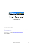
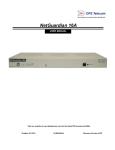
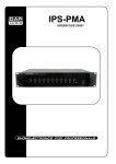
Basic Sound Engineering, PP271 Fall 2011
Chapter 10: Systems Integration, Gain Structure
So far, we have been looking at individual components, and we’ve worked our way from the
definition of sound and the way it works in a room through each of the stages of a system,
beginning with the microphone and ending with the loudspeakers. Now we need to apply all
that detail to a complete system, stepping from the micro to macro level in sound engineering.
Naturally, that requires us to look at more details as we go along, but we should be applying all
the things we’ve learned about components along the way – we already have the tools at hand to
build the system.
Recall that one of the things we’ve been coming back to over and over is the notion that a sound
system can be thought of as a voltage gain control system. That is, once we exit the realm of air
pressure – once we get to the input transducer (microphone) we have converted the energy into
an electrical signal. In modern systems, the most important quantity to understand at each step
is the voltage level – recall that voltage is also called electromotive force and is equivalent to
pressure in the acoustical realm – if we know the voltage (and presumably the impedance) we
can generally calculate everything else. Also, since voltage uses the 20*Log formula, the
calculations can be simplified by those relationships we have committed to memory – a 6dB
increase is a doubling of voltage, a 20dB increase is 10 times the voltage, 40dB is 100 times the
voltage. That means we can get a pretty quick understanding of the level at any stage based on
the voltage gain of the previous stage.
For example, we have a microphone (Shure SM58) with an open circuit sensitivity of -54dBu
(measured at 1Pascal or 94dB SPL). We could crank this through the log formula to determine
that our microphone in this 94dB SPL sound field will produce about 0.00154 volts (which
could be stated as 1.54 millivolts) – but we don’t absolutely need to do that since we can
compare stage to stage in our system without ever converting back out of dB notation. So, let’s
plug this microphone into a mixer, in this case an Allan & Heath ML3000. You will find the
user manual for that mixer and specification sheets for the SM58 and other equipment
mentioned in this section on the class website. The ML3000 manual has a great illustration of
the mixer’s internal gain structure, reproduced below.
Figure 10 - 1: Allen & Heath ML3000 Gain Structure
PP271 Basic Sound Engineering, Fall 2011
183
From this chart (or the specifications for the mixer) we can see that our microphone falls well
within the input operating range of -60dBu to +11dBu, and that we can expect to be able to
adjust the input gain so that we will have an optimal working level signal for each stage of the
mixer’s electronics. If we adjust the gain control, and the various other mixer controls between
the input fader to the output fader so that our microphone input results in an output of +4dBu (or
zero on our volume indicator meters on the mixer), we can say that our mixer here is supplying
a voltage gain of 58dB (-54dBu to +4dBu). We could also work that out using the log formula
by plugging in the input voltage of .00154v and the output voltage of 1.23V (which we recall is
the voltage level for +4dBu).
dB = 20 * Log(
E1
)
E0
or
" 1.23v %
dB = 20 * Log$
'
# 0.00154v &
€
and
dB = 20 * Log(798.701) = 58.04dB
Let’s assume we’re using€one of the amplifiers and speakers from our examples in chapter 9,
the QSC Powerlight 3 PL340. We could insert any number of stages between the mixer and the
€ but for all of them our goal would be to have unity gain – we would
amplifier in our system,
like to see the output voltage of each of these stages be equal to the input voltage, since we
remember that our amplifier input sensitivity is such that we can expect maximum output from
the amp with around 3.92v on the inputs, and that around 11v is it’s maximum input level
before clipping at the nominal input sensitivity setting on the amp. We also know that the amp
will produce a gain of 36.4db at that nominal setting. If that is the case, then we could expect
our 1.23v signal from the mixer applied to the input of the amplifier would produce an output
voltage of about 81.3 volts. We come up with that number either by doing the same log
calculation we did above only in reverse, knowing the final dB number and the initial voltage
number, or we could use our relationships that we know. 36 = 6x6, so we could just reason that
a 36dB increase is about 6 doublings of the voltage. That would get us to about 79v which is
pretty close to our calculated 81 volts.
(1) 2 x 1.23 = 2.46
(2) 2 x 2.46 = 4.92
(3) 2 x 4.92 = 9.84
(4) 2 x 9.84 = 19.68
(5) 2 x 19.68 = 39.36
(6) 2 x 39.36 = 78.72
So, now we have a voltage output figure for the Amp, if we apply that to a speaker, we could
use the speaker specification to figure out what our acoustical output would be. In the case of
the speaker we used for the last chapter, the JBL AM7315/95, we know that the nominal
impedance of the speaker is 8Ω, and we know that the SPL output of the box is stated to be
108dB SPL at 1 meter when it is dissipating one Watt. Since we have a voltage output and the
impedance, we can calculate the power dissipated by the speaker using the power equation:
PP271 Basic Sound Engineering, Fall 2011
184
E2
R
where P is the Power dissipated, E is the voltage and R is the resistance – or the impedance in
this case. We will ignore the small error in calculation that results from the fact that this formula
is technically accurate only for DC circuits – for our purposes it is close enough to use.
€
Substituting in the numbers:
(78.2) 2 volts
P=
8Ω
or
P=
P = 764.4Watts
Now, we can figure out what the SPL output of the speakers would be expected to be at this
power level. We could use the power log formula to work out the expected difference between 1
Watt and 764.4 Watts as follows:
€
"P %
dB = 10 * Log$ 1 '
# P0 &
or
" 768.4 %
dB = 10 * Log$
'
# 1 &
dB = 10 * 2.885
dB = 28.85
Note we used the 10 Log formula since we are working with power. So, we’d expect 28.85dB
higher level with the 768.4 Watts than we got with 1 Watt, meaning we would expect to get
€ the speaker. The other way we could work this is to use our rule
136.8 dB SPL at 1 meter from
of thumb that we expect to see a 3dB increase for every doubling of power. So, we look to see
how many doublings we’d get between 1 and 768.4 Watts.
(1) 1 x 2 = 2
(2) 2 x 2 = 4
(3) 4 x 2 = 16
(4) 16 x 2 = 32
(5) 32 x 2 = 64
(6) 64 x 2 = 128
(7) 128 x 2 = 256
(8) 256 x 2 = 512
(9) 512 x 2 = 1024
9 doublings gets us just above the 768 Watts – and that would be 9 x 3 or about 27dB increase.
We’re within 1.85 dB of our calculated number, which is very close in this context. You might
object that 1024 seems considerably higher than 768 – that’s another 256 Watts, shouldn’t that
count as a big difference? The answer is not really, remember that in order to get just a 3dB
difference we have to DOUBLE the power/system – two steps back down the ladder, 256 Watts
is significant, once we get up to the level of 700 watts it’s chump-change. In the same way, that
1.85 dB difference is really insignificant – recall that a 1dB SPL level change is the level we
PP271 Basic Sound Engineering, Fall 2011
185
said was just audible by trained listeners. Also, if you go back to the specifications, you’ll
notice that 136.8dB is getting very close to the maximum peak level for this speaker, so our
system headroom is pretty thin. We don’t have any room to get louder if we need to, and we
risk distortion if we have louder sounds presenting at the microphone unless we turn things
down someplace. On the other hand, is this quite loud enough for our gig? We could do a quick
check – assuming we’re in the same room we were looking at in chapter 9a, our back row of
audience is about 38’ from the speaker location, and if we do the same calculations we did back
then on our level difference we’ll find:
Dr )
L P = L PR + 20 log( D
m
3.28 ft
38 ft
or
LP = 136dB + 20log(
)
and
LP = 136dB + (−21.27dB) = 114.73dB
So, €
we’ve got pretty high level all the way to the back of the house.
But wait you object, didn’t you say that in an enclosed environment the free-field calculation
doesn’t
€ work and the level will really be louder? Well, funny you should mention that. Yes, the
overall level would indeed be higher, particularly beyond the critical distance in the room. But,
remember from that critical distance graph that the direct sound continued to diminish in
exactly the same way it does in the free field, it’s just that the total measured sound level no
longer dropped off with the direct sound. So, since the direct sound will be the carrier of the
intelligibility of the signal, it still is the thing we’re interested in when we do our calculation for
the level. So, we still can use the free-field calculation, we just have to remember that we may
find there is enough noise from reflections that the total measured level will not fall off in the
same way as the direct sound. This is another reason that we are concerned with dispersion
patterns and reflections from wall surfaces – if we use pattern control carefully we can reduce
the amount of reflections that we need to deal with making the above calculation more realistic.
So many formulas! But there are more! When we put a system together for a space, we have an
idea now how to figure out the SPL at a given distance, and we have a way to think about how
the speakers will cover the space. Left out of the factors so far is some way to know if we will
run into problems with feedback – that is, can we get the system loud enough to deliver the
level we need at the back of the house without getting it so high that microphones on the stage
will generate feedback into the system? Careful selection of speaker dispersion patterns and
crafty placement and aiming of those boxes will help. Careful selection of the microphone will
also help – that is, you wouldn’t want to use an omni-directional mic very close to a wide
dispersion speaker. But, is there a way to figure out what gain you actually need, and then
whether or not your system can produce that gain without feedback?
Yes, there is a way to do calculations to predict this, and systems installers use this all the time.
It’s based on two calculations, Potential Acoustic Gain (PAG) and Needed Acoustic Gain
(NAG). You will hear installation specialists call this PAG/NAG design (Those guys sure have a
way with words.) The idea here is that if you can figure out how much gain your system is
capable of delivering without running into feedback (PAG), and if you can figure out how much
gain you need in order to make the system deliver a level at the back of the house that is at least
PP271 Basic Sound Engineering, Fall 2011
186
as loud as the acoustical level that the front row can hear from the stage (NAG), then all you
have to do is make sure that the PAG is at least as high as the NAG and you should be good to
go.
What are the factors we need to know in order to calculate these two values? For NAG, Needed
Acoustic Gain, we really only need to know two things – how far from the source to the closest
listener, and how far from the loudspeaker to the furthest audience seats?
For the PAG, Potential Acoustic Gain, we need to know how far the source is from the
microphone, how far the microphone is from the nearest speaker, how far that speaker is from
the furthest listener, and how far the source is from that same furthest listener. We also need to
know one more thing if we have more than one microphone open – how many of them are open.
So, our variables look like this:
D0 = Distance from the source to the back of the audience
D1 = Distance from the source mic to the nearest loudspeaker
D2 = Distance from the back of the audience to the nearest loudspeaker (to them)
Dn = Distance from the source to the front of the audience
Ds = Distance from the source to the microphone
Nm = Number of open microphones
We’d calculate the NAG using the simple formula:
NAG = 20 * Log
D0
Dn
PAG is now calculated, and it is essentially based on the distance formula we have used before.
The formula for calculating PAG with just one microphone would be:
"D *D %
€
PAG = 20 * Log$ 0 1 '
# Ds * D2 &
If we have more than one open microphone, we need to modify the formula to account for the
multiple paths from microphones to the loudspeaker as follows:
"D *D %
PAG = 20 * Log$ 0 1 ' −10 * Log( N m )
# Ds * D2 &
Finally, if we are using the PAG to figure out system stability (freedom from feedback) then we
want to include a factor that would ensure our system would be free of feedback problems. It is
generally understood that running a system about 6dB below the absolute calculated PAG will
€
give you a good chance
of stable feedback-free operation, so we add into the calculation a 6dB
Feedback Stability Margin (FSM), and we have:
€
"D *D %
PAG = 20 * Log$ 0 1 ' −10 * Log( N m ) − 6dB
# Ds * D2 &
Looks complicated, but really none of the variables are hard to find. Let’s run the PAG
calculation for the system we’ve been looking at. We need some more information than we’ve
had so far, so I will arbitrarily define values that might make sense on our stage. Let’s say we
€
have 12 microphones
on the stage, and that our typical distance from the source (singer or
PP271 Basic Sound Engineering, Fall 2011
187
instrument) to the mic is about 3”(0.25 feet). Our stage is relatively small, but if we work with
our cluster arrangement from chapter 9a, we need to take into account both vertical and
horizontal displacement – what we’re interested in is the “crow-flies” distance from the mic to
the speaker. Let’s say that for the mic closest to the speaker – probably the vocalist – that
distance is going to be around 10’. We already noted the distance from the speaker to the back
row is about 38’, so since the vocalist is about 3’ upstage of that, we’d use 41’ for our source to
last row distance. The distance from the first row to our vocalist looks like about 12’.
So, plugging in our values we have:
D0 = Source to the back of the audience = 41’
D1 = Source mic to the nearest loudspeaker = 10’
D2 = Back of the audience to the nearest loudspeaker = 38’
Dn = Source to the front of the audience = 12’
Ds = Source to the microphone = 0.25’
Nm = Number of open microphones = 12
So, first working out the NAG:
NAG = 20 * Log
41'
12'
so
NAG = 20 * Log(3.416)
and
NAG = 10.67dB
Let’s round that off to 11dB Acoustic Gain required
Now, putting those values €
in our final PAG formula, we have:
" 41'*10' %
PAG = 20 * Log$
' −10 * Log(12) − 6dB
# 0.25'*38' &
so
" 410 %
PAG = 20 * Log$
' −10 * Log(12) − 6dB
# 9.5 &
and
PAG = 20 * Log(43.157) −10 * Log(12) − 6dB
or
PAG = (20 *1.635) − (10 *1.079) − 6
so
PAG = 15.91dB
Or, for all practical purposes, let’s say 16dB.
So, our calculation tells us that we needed 11dB gain, and our system is able to produce 16dB –
€ to go – with attention to placement, we should be able to get the necessary
we should be good
PP271 Basic Sound Engineering, Fall 2011
188
gain to allow the last row to hear the sound at the same level as the first row would be able to
hear the direct sound from the performance.
An interesting exercise is to see what happens if we could reduce the number of microphones.
Suppose we managed to drop that down to 6 microphones by using direct inputs for some of our
instruments, or by carefully grouping our performers around microphones? Plugging the
numbers back into our formula but changing the microphone factor, we would discover that the
new PAG number would be almost 19dB – by ditching 6 mics, we got 3dB additional gain.
Does this remind you of any other similar relationships? Of course, what we did was cut our
number of microphones in half, and we got a 3dB increase in gain – this illustrates a slightly
counter-intuitive rule for microphones – every time you double the number of microphones, you
introduce a 3dB reduction in overall system gain (and a 3dB increase in noise to boot).
PAG/NAG calculations are very handy when you are trying to work out whether or not you’re
going to be able to make a system work. Over time, if you do enough systems, you’ll develop a
more or less seat-of-the-pants sense of whether or not a system is going to work. But, as you can
see, it’s really pretty easy to crank out the numbers to give yourself a little more confidence.
Setting System Gain
One of the most important things you can do to make a system work correctly is to get the
system gain structure right. Put another way, get it wrong and you’ll be fighting either excess
noise or inadequate gain all night. There are two main approaches to setting overall system gain,
the unity method and the clip method. Actually, there is a third method unfortunately used by
way too many people – the slap-it-together-and-hope method. Let’s assume that you would
prefer not to use that last one. As to whether to use the unity or the clip method, it really comes
down to the old reliable “it depends” answer. If you are routinely going to be running a system
against it’s limits because you need to wring every dB out of it, then the clip method is probably
your best bet. But if your system is not going to be pushed to the extreme, the unity method is a
little easier, and requires a bit less gear and time to set up.
Tools you need for either method include some kind of signal generator (you can use an iPod or
CD player, but a source that can generate both sine waves and pink noise at a known level is
best), a volt meter that reads in RMS (most inexpensive multi-meters are fine for this, even the
really cheapies though you should be aware that many of those do not read true RMS – they’re
still good enough for this task), and an SPL meter to measure the final acoustical output of the
loudspeaker (and here you can substitute your ears at the simplest level). If you want to use the
clip method, you definitely need the ability to generate sine wave test signals of around 200400Hz and you additionally need either an oscilloscope to view output wave shape or a cheap
piezoelectric speaker with some clip leads attached to indicate harmonic distortion.
Unity Method:
Set up your signal generator to produce an appropriate level signal for the input you are using.
Usually, this will be a microphone input, so you will want a signal that is somewhere in the
range of 0.1 volt or less (if you know what your typical microphone output will be, use that as a
guideline). If you are using a line-level input, you may need a signal in the range of 1 volt.
Let’s use our figures from above for the microphone level, and see if we can generate a sine
wave signal that would be equivalent to the signal arriving from our SM58 in the 94 dBSPL
sound field at the microphone input – we’d be shooting for something in the range of .001 volts,
or one millivolt. The iPhone application I used in class to demonstrate this technique is called
PP271 Basic Sound Engineering, Fall 2011
189
SignalSuite and is part of a suite of iPhone and iPad apps made by Studio Six Digital.
SignalSuite costs $9.99 – so if you have an iPhone or an iPod Touch or an iPad it’s an
inexpensive signal generator. There are also free or very inexpensive SPL meters available for
the iPhone, but the catch here is that the microphone input on the iPhone has a limiter, and will
be into clipping well before you get to the kind of levels you may need to measure in setting up
a sound system (the new 4s has greatly improved this, and IOS 5 has improved the way the
phone or tablet handles low frequencies). There are various quality external microphones
available for the iPhone all the way up to very sensitive calibrated microphone inputs with
which you can do sophisticated testing (for more sophisticated prices of course). You also can
find calibration tracks for any mp3 player – you just need to get pink noise, a 1KHz tone and a
400KHz tone that you can play from the player. So, here are the steps I take to set the gain using
the unity method:
1. Set the signal generator to produce a 1KHz Sine Wave tone. Throw the balance all the
way to one side for convenience, and use the voltmeter to measure the output RMS
voltage by measuring across the appropriate terminals. (On an iPod or similar device,
get an adaptor to go from the dock or from the headphone out to a stereo pair of RCA
leads, and then use adaptors on those to get to your microphone XLR – ultimately the
shield of the RCA goes to Pin 3 and the post of the RCA goes to pin 2 on the XLR, with
pin 1 not connected). In this case, adjust the level control until you see an output level of
roughly 1 to 1.5 millivolts (.0015v).
2. IMPORTANT – MAKE SURE PHANTOM POWER IS TURNED OFF ON THE
MIXER INPUT YOU WILL USE – failure to do this will toast your iPhone or other
mp3 device, though it probably would not damage a signal generator designed for pro
audio (in fact, some of those are designed to work using phantom power).
3. Switch off the generator and connect the output of the generator to a microphone input
on the mixer. Make sure that your amplifier is off or disconnected from the system at
this point, and that the output connector of the mixer is disconnected.
4. Make sure that the gain or trim control on the channel is at it’s maximum attenuation
level – in other words, it’s reducing the input signal to the maximum amount possible.
Usually, this will be turned all the way counter-clockwise.
5. Set the input channel fader to the “0dB” position, patch it to a submaster and set that to
its “0dB” position, if necessary patch that submaster to the main outputs and set the
main output fader to its “0dB” position.
6. Switch on the signal generator, and slowly adjust the input gain on the channel strip until
the mixer’s output meter reads “0”.
7. Measure the output voltage on the mixer’s corresponding output. If the mixer meters are
correctly calibrated VI meters, you should be reading something on the order of 1.23
volts RMS.
8. Apply this signal to the next stage in the system, and adjust it’s input level so that it
produces an output signal of the same level – in other words, set it’s gain so that it is a
unity gain device – output level equals input level (this assumes the next stage is NOT
the amplifier).
9. Continue through the system until you get to the amplifier.
PP271 Basic Sound Engineering, Fall 2011
190
10. When you get to the amplifier, it is a good idea to go back to the mixer and switch your
source from the 1KHz tone to a pink noise signal. Since the pink noise has a lower crest
factor1 than the sine wave, you will need to adjust your signal generator level up until
the mixer meter returns to the “0vu” level (expect the level to be roughly 6dB down
from the sine wave level). We switch to pink noise both because nobody wants to listen
to a 1KHz signal at full system level, and because the high crest factor of the sine wave
is much harder on the amplifier than either pink noise or music, so it is an unrealistic test
of the amplifier’s function. As well, for the final level adjustment you are interested in a
signal that is broader than a single frequency. If you don’t have a good source of pink
noise, it is perfectly acceptable at this point to switch to music that is similar to what will
be in the program for the level test.
11. At the amplifier, first make sure the input sensitivity knob is turned all the way down,
then apply the signal and using the SPL meter, adjust the amplifier until you get the
desired level2. Again here, if you don’t have an SPL meter, you can use your ears –
ultimately those are what you will use to run the system anyway. Set the level so that it
feels about where you think you will be running the system.
12. Now, if you have not already done so, go back to the mixer and switch to music or other
program that is similar to what you will be using the system for, crank it up and listen to
the system in the room.
13. Finally – during sound check adjust the input gains for your microphones so that they
give you a good working level with your faders at their “0” or unity positions. When you
mix the show, you don’t use the gain controls, you use the faders – what you have done
in these steps is calibrated the entire system so that it will respond to your adjustments at
the mixer, and so that you have the optimum range of adjustment at the mixer.
Clip Method:
The unity method will work fine for most systems, but occasionally you know that you will be
pushing a system hard and you want to know what it is able to do beyond the indications of the
meters and clip lights on the components. Most of those meters and clip lights are set
conservatively – the manufacturers don’t want people complaining that their systems sound bad
so they set clip lights to come on well before the system will actually clip. One clue to this is the
typical instruction for operating a mixer – you are told to adjust the signal until the clip lights
flicker on and off at the highest points of the signal. If they were really indicating clipping, you
would be instructed to set the system so that they never light at all! Of course, this does give
you a lot of room for error – remember that if you use the clip method to adjust your system,
1
Uh oh - New Term Alert! Crest Factor: The ratio of the PEAK value to the RMS value of a waveform over a
specified time interval. Frequently, 50ms is used as the time interval – so Crest Factor tells us how “dense” the
signal is – how much of it is at high level. A signal with lots of transient peaks but not very high level between will
result in a low crest factor, one which is heavily compressed so that it has a consistently high level throughout will
have a high crest factor. A square wave has a crest factor of 0dB, a sine wave of -3dB, pink noise of about -10dB
(interestingly, about the same as a Rob Zombie song), earlier ballad rock, probably around -20dB.
2
And, here we find one of the disadvantages to the powered speakers – often there is no easily adjustable input
level control. So, it often is useful to have a separate speaker processor or distribution amplifier, which gives you
level control for the feed to the powered speaker. Some powered speakers have networkable controls specifically
for this purpose.
PP271 Basic Sound Engineering, Fall 2011
191
you will have to pay much closer attention to your levels to avoid audible distortion. But, in
most cases when you take this approach, you find that you may wind up with less system noise
and certainly more potential for gain.
So, the clip method is similar to the unity method except that at each stage of the system, we
want to find the point where the system actually does go into distortion. We set the entire
system so that it is right on the edge of distortion, and then we pull back the initial stage to our
normal operating level, and we know from then on that we will not have distortion in the rest of
the system as long as we don’t have it at the mixer.
So, we start off the same way as we did above:
1. Set the signal generator to produce a 400Hz Sine Wave tone. Throw the balance all the
way to one side for convenience, and use the voltmeter to measure the output RMS
voltage by measuring across the appropriate terminals. (On an iPod or similar device,
get an adaptor to go from the dock or from the headphone out to a stereo pair of RCA
leads, and then use adaptors on those to get to your microphone XLR – ultimately the
shield of the RCA goes to Pin 3 and the post of the RCA goes to pin 2 on the XLR, with
pin 1 not connected). In this case, adjust the level control until you see an output level of
roughly 1 to 1.5 millivolts (.0015v).
2. IMPORTANT – MAKE SURE PHANTOM POWER IS TURNED OFF ON THE
MIXER INPUT YOU WILL USE – failure to do this will toast your iPhone or other
mp3 device, though it probably would not damage a signal generator designed for pro
audio (in fact, some of those are designed to work using phantom power).
3. Switch off the generator and connect the output of the generator to a microphone input
on the mixer. Make sure that your amplifier is off or disconnected from the system at
this point, and that the output connector of the mixer is disconnected.
4. Make sure that the gain or trim control on the channel is at it’s maximum attenuation
level – in other words, it’s reducing the input signal to the maximum amount possible.
Usually, this will be turned all the way counter-clockwise.
5. Set the input channel fader to the “0dB” position, patch it to a submaster and set that to
its “0dB” position, if necessary patch that submaster to the main outputs and set the
main output fader to its “0dB” position.
6. Switch on the signal generator, and slowly adjust the input gain on the channel strip until
the mixer’s output distorts. In order to discover this point, either connect a piezoelectric
speaker across the output leads, or connect them to an oscilloscope. Since you are using
a 400Hz tone and the piezoelectric speaker can’t produce any output below about
1200Hz, when you hear it make noise you know you have harmonic distortion present.
7. Crank this signal back very slightly until it sits just below clipping. Measure the voltage
output of the mixer (for a recent test, I measured about 7.8 volts on one mixer at this
point, or about 20dBu).
8. Apply this signal to the next stage in the system with the input level of the stage at its
minimum level and check to see if it is already clipping. If so, you may need to insert an
attenuator between the mixer and this stage (Do NOT adjust the mixer level down, the
entire point of the exercise is to allow the mixer and this stage to reach clip at the same
PP271 Basic Sound Engineering, Fall 2011
192
point). The objective here is to adjust this stage so that it just clips on the clipped signal
sent from the mixer. Then as with the mixer, you adjust the input level of this stage back
down until it just stops clipping, and continue on to the next stage. At this point, you
know that both the mixer and this stage will clip if the mixer is driven into clipping, and
you know that as long as the mixer does NOT go into clipping, neither will this stage.
9. Continue with this process with each stage until you get to the amplifier.
10. Now, go back to the mixer switch to pink noise and reduce the gain on your input until
you read “0vu” on your mixer output meter.
11. At the amplifier, first make sure the input sensitivity knob is turned all the way down,
then apply the signal and using the SPL meter, adjust the amplifier until you get the
desired level. Again here, if you don’t have an SPL meter, you can use your ears –
ultimately those are what you will use to run the system anyway. Set the level so that it
feels about where you think you will be running the system.
12. Now, if you have not already done so, go back to the mixer and switch to music or other
program that is similar to what you will be using the system for, crank it up and listen to
the system in the room.
13. Finally – during sound check adjust the input gains for your microphones so that they
give you a good working level with your faders at their “0” or unity positions. When you
mix the show, you don’t use the gain controls, you use the faders – what you have done
in these steps is calibrated the entire system between the microphone and the amplifier
so that it will clip at the same point and respond to your adjustments at the mixer, and so
that you have the optimum range of adjustment at the mixer.
Powered Speakers:
You might have to adjust this process slightly if you have self-powered speakers. Often, there is
no immediately visible level adjustment for these, so your only adjustment point is the output of
the mixer or the stage immediately prior to the loudspeaker. Many of these actually do have
input sensitivity adjustments; you just need a small screwdriver to make the adjustment. But,
that means you may not have the option of starting with the amplifier sensitivity turned down.
So, just be aware that with powered speakers, you want to be sure that you aren’t sending a fulltilt line level signal to the box when you begin the adjustment. Many systems that take
advantage of self-powered speakers make use of a speaker management system that often
includes internal DSP options taking the place of a number of the stages of a traditional system.
PP271 Basic Sound Engineering, Fall 2011
193