1
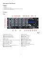
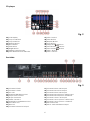
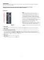
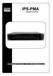
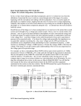
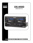
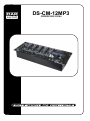
DS-CM-12MP3
ORDERCODE D2184
Congratulations!
You have bought a great, innovative product from DAP Audio.
The DAP Audio DS-CM-12MP3 brings excitement to any venue. Whether you want simple plug-&-play
action or a sophisticated show, this product provides the effect you need.
You can rely on DAP Audio, for more excellent audio products.
We design and manufacture professional audio equipment for the entertainment industry.
New products are being launched regularly. We work hard to keep you, our customer, satisfied.
For more information: [email protected]
You can get some of the best quality, best priced products on the market from DAP Audio.
So next time, turn to DAP Audio for more great audio equipment.
Always get the best -- with DAP Audio !
Thank you!
Dap Audio
Dap Audio DS-CM-12MP3™ Product Guide
Warning.........................................................................................................................................................................2
Safety-instructions...................................................................................................................................................2
Operating determinations.....................................................................................................................................3
Return procedure...................................................................................................................................................4
Claims.......................................................................................................................................................................4
Description...................................................................................................................................................................5
Overview.................................................................................................................................................................5
Frontside..................................................................................................................................................................5
SD-card player........................................................................................................................................................6
Backside..................................................................................................................................................................6
Installation....................................................................................................................................................................7
Functions...................................................................................................................................................................... 7
SD-card player operations........................................................................................................................................11
Set Up and Operation.................................................................................................................................................13
Maintenance...............................................................................................................................................................15
Replacing the crossfader...........................................................................................................................................15
Troubleshooting...........................................................................................................................................................15
Product Specifications................................................................................................................................................16
1
WARNING
FOR YOUR OWN SAFETY, PLEASE READ THIS USER MANUAL CAREFULLY
BEFORE YOUR INITIAL START-UP!
Unpacking Instructions
Immediately upon receiving this product, carefully unpack the carton and check the contents to ensure
that all parts are present, and have been received in good condition. Notify the dealer immediately and
retain packing material for inspection if any parts appear damaged from shipping or the carton itself
shows signs of mishandling. Save the carton and all packing materials. In the event that a fixture must be
returned to the factory, it is important that the fixture be returned in the original factory box and packing.
Your shipment includes:
• DAP DS-CM-12MP3
• power cable - 2m
• User manual
WARNING
CAUTION!
Keep this system away from rain and moisture!
SAFETY INSTRUCTIONS
Every person involved with the installation, operation and maintenance of this system has to:
be qualified
follow the instructions of this manual
CAUTION! Be careful with your operations.
With a dangerous voltage you can suffer
a dangerous electric shock when touching the wires!
Before you initial start-up, please make sure that there is no damage caused by transportation. Should
there be any, consult your dealer and do not use the system.
To maintain perfect condition and to ensure a safe operation, it is absolutely necessary for the user to
follow the safety instructions and warning notes written in this manual.
Please consider that damages caused by manual modifications to the system are not subject to
warranty.
This system contains no user-serviceable parts. Refer servicing to qualified technicians only.
IMPORTANT:
The manufacturer will not accept liability for any resulting damages caused by the nonobservance of this manual or any unauthorized modification to the system.
Never let the power-cord come into contact with other cables! Handle the power-cord and all
connections with the mains with particular caution!
2
Never remove warning or informative labels from the unit.
Never use anything to cover the ground contact.
Never leave any cables lying around.
Do not insert objects into air vents.
Do not connect this system to a dimmerpack.
Do not switch the system on and off in short intervals, as this would reduce the system’s life.
Do not open the device and do not modify the device.
Do not drive the inputs with a signal level bigger, than required to drive the equipment to full
output.
Do not plug Mics into the console (or stagebox) while Phantom Power is on. Also mute the monitor
/ Pa system when turning Phantom Power on or off. Allow the system to adjust for a couple of
seconds, before setting the input gains.
Only use system indoor, avoid contact with water or other liquids.
Avoid flames and do not put close to flammable liquids or gases.
Always disconnect power from the mains, when system is not used. Only handle the power-cord
by the plug. Never pull out the plug by tugging the power-cord.
Always operate the unit with the AC ground wire connected to the electrical system ground.
Make sure you don’t use the wrong kind of cables or defective cables.
Make sure that the signals into the mixer are balanced, otherwise hum could be created.
Make sure you use DI boxes to balance unbalanced signals; All incoming signals should be clear.
Make sure that the available voltage is not higher than stated on the rear panel.
Make sure that the power-cord is never crimped or damaged. Check the system and the powercord from time to time.
Please turn off the power switch, when changing the power cord or signal cable, or select the
input mode switch.
Extreme frequency boosts in connection with a high input signal level may lead to overdriving
your equipment. Should this occur, it is necessary to reduce the input signal level by using the
INPUT control.
To emphasize a frequency range, you don’t necessarily have to move its respective control
upward; try lowering surrounding frequency ranges instead. This way, you avoid causing the next
piece of equipment in your sound path to overdrive. You also preserve valuable dynamic reserve
(“headroom”)
Avoid ground loops! Always be sure to connect the power amps and the mixing console to the
same electrical circuit to ensure the same phase!
If system is dropped or struck, disconnect mains power supply immediately. Have a qualified
engineer inspect for safety before operating.
If the system has been exposed to drastic temperature fluctuation (e.g. after transportation), do
not switch it on immediately. The arising condensation water might damage your system. Leave
the system switched off until it has reached room temperature.
If your Dap Audio device fails to work properly, discontinue use immediately. Pack the unit
securely (preferably in the original packing material), and return it to your Dap Audio dealer for
service.
Repairs, servicing and electric connection must be carried out by a qualified technician.
For replacement use fuses of same type and rating only.
WARRANTY: Till one year after date of purchase.
OPERATING DETERMINATIONS
This system is not designed for permanent operation. Consistent operation breaks will ensure that the
system will serve you for a long time without defects.
If this system is operated in any other way, than the one described in this manual, the product may suffer
damages and the warranty becomes void.
Any other operation may lead to dangers like short-circuit, burns, electric shock, etc.
You endanger your own safety and the safety of others!
Improper installation can cause serious damage to people and property !
3
Connection with the mains
Connect the device to the mains with the power-plug.
Always pay attention, that the right color cable is connected to the right place.
International
L
N
EU (including UK)
From April 2004
Brown
Blue
Green/Yellow
North America
Pin
Black
White
Green
Phase
Neutral
Protective Earth
Make sure that the device is always connected properly to earth!
Return Procedure
Returned merchandise must be sent prepaid and in the original packing, call tags will not be issued.
Package must be clearly labeled with a Return Authorization Number (RMA number). Products returned
without an RMA number will be refused. Highlite will not accept the returned goods or any responsibility.
Call Highlite 0031-455667723 or mail [email protected] and request an RMA prior to shipping the fixture.
Be prepared to provide the model number, serial number and a brief description of the cause for the
return. Be sure to properly pack fixture, any shipping damage resulting from inadequate packaging is the
customer’s responsibility. Highlite reserves the right to use its own discretion to repair or replace
product(s). As a suggestion, proper UPS packing or double-boxing is always a safe method to use.
Note: If you are given an RMA number, please include the following information on a piece of paper
inside the box:
1) Your name
2) Your address
3) Your phone number
4) A brief description of the symptoms
Claims
The client has the obligation to check the delivered goods immediately upon delivery for any shortcomings and/or visible defects, or perform this check after our announcement that the goods are at their
disposal. Damage incurred in shipping is the responsibility of the shipper; therefore the damage must be
reported to the carrier upon receipt of merchandise.
It is the customer's responsibility to notify and submit claims with the shipper in the event that a fixture is
damaged due to shipping. Transportation damage has to be reported to us within one day after receipt
of the delivery.
Any return shipment has to be made post-paid at all times. Return shipments must be accompanied with
a letter defining the reason for return shipment. Non-prepaid return shipments will be refused, unless
otherwise agreed in writing.
Complaints against us must be made known in writing or by fax within 10 working days after receipt of the
invoice. After this period complaints will not be handled anymore.
Complaints will only then be considered if the client has so far complied with all parts of the agreement,
regardless of the agreement of which the obligation is resulting.
4
Description of the device
Features
• 10 inputs
• 3 outputs
• Assignable cross fader
• Gain, bass, mid, treble, pan control for each channel
• Headphone with split function
Overview
Front
Fig. 1
1) Mic Balanced Input
2) Mic 3 Mute Switch + LED
3) Mic 2 Mute Switch + LED
4) Mic Channel Treble Control
5) Mic Channel Bass Control
6) Mic 1 Level
7) Mic 2 Level
8) Channel Input Selector Phono-aux/ SD/ Line
9) Channel Gain Control
10) Channel Treble Control
11) Channel Mid Control
12) Channel Bass Control
13) Channel Fader
14) Channel Input Selector Aux 4/SD/Line 4
15) Channel Cue Switch
16) Master Volume Fader
17) Mono Switch
18) X-assign A Selector
19) Fader Start A Switch
20) Crossfader
21) Fader Start B Switch
22) X-assign B Selector
23) Master Balance Control
24) Output L Signal VU-meter
25) Output R Signal VU-meter
26) Power Switch
27) Zone Volume Control
28) Cue/ PGM Mix Fader
29) Cue (Headphone)Level Control
30) Headphone Output
31) Aux Input
5
SD-player
Fig. 2
32) LCD Display
33) Loop Out Button
34) Loop In Button
35) Reloop Button
36) SD card slot
37) Time Buton
38) Single Button
39) Folder/ Track Encoder
40) Pitch Bend Amount Indicator
41) Pitch Control
42) Pitch Button
43) Repeat Button
44) Cue Button
45) Play/Pause
Button
46) Fast Reverse
Button
47) Fast Forward
Button
48) Pitch – Button
49) Pitch + Button
Backside
Fig. 3
50) Channel 2 GND
51) Channel 1 GND
52) AC Inlet
53) Master XLR Balanced Out
54) Output Trim Control
55) Player Control B
56) Fader Control A
57) Master RCA Unbalanced Out
58) Zone RCA Out
59) Rec Out
60) Channel 4 Line 4 RCA input
61) Channel 3 Line 4 RCA Input
62) Channel 3 Aux 3 RCA Input
63) Channel 2 Line 2 RCA Input
64) Channel 2 Aux 2/Phono 2 RCA Input
65) Channel 2 Aux 2/Phono 2 Selector
66) Channel 1 Line 1 RCA Input
67) Channel 1 Aux 1/Phono 1 RCA Input
68) Channel 1 Aux 1/Phono 1 Selector
69) Mic Attenuator
70) Mic 2 Jack Unbalanced Input
6
Installation
Remove all packing materials from the DS-CM-12MP3. Check that all foam and plastic padding is
removed. Connect all cables.
Always disconnect from electric mains power supply before cleaning or servicing.
Damages caused by non-observance are not subject to warranty.
Functions
1. MIC
Electronically balanced XLR-type input for
connecting low impedance microphone. The
input has exremely low noise hum. When
connecting a microphone make sure that the
pin assignment is correct. Always make sure to
read the manual of the microphone you want to
connect. The XLR- input is not suitable for
connecting an additional mixing console, FX- unit,
etc. You have to use the LINE-inputs, when
connecting this kind of equipment.
Note: When connecting signal sources, please
make sure that the corresponding channel faders
and the master faders are at their minimum
Fig. 4
settings. Otherwise, unpleasant plug-in noise can
occur.
2. MIC 2 Mute
Press this switch to mute the MIC 2 input. The Mute LED will light if the mute function is activated.
3. MIC 1 Mute
Press this switch to mute the MIC 1 input. The Mute LED will light if the mute function is activated.
4/ 5. Mic Channel EQ Treble/ Bass
The Zone’s Equalizer section allows shaping of the incoming audio signal. The Mic channel is fitted
with a 2-band EQ. The Treble (4) and Bass (5) shelving controls have their frequencies fixed at
10 Khz and 100 Hz respectively. The treble band has up to 15 dB cut and up to 12 dB boost. The bass
band has up to 23dB cut and up to 12 dB boost.
6. MIC 1 Level
Controls the volume of the Mic 1 (1) input.
7. MIC 2 Level
Controls the volume of the Mic 2 (70) input.
7
8. Selection Switch (Phono Aux / SD/ Line )
With this switch you can select between two sets
of inputs or the built in SD-player per channel.
Set the Aux/Phono (65, 68) selector in phono
position if you want to connect a turntable. To
the Aux/Phono (64, 67) input on the rearpanel.
9. Gain
Use this control to match the connected devices
optimally to your DS-CM-12MP3. With the fader
and Master fader set to ¾ stroke, Adjust the gain
with a loud input signal in such a way that the
Red LED’s on the Master VU-meters (24, 25) do not
light up.
10/ 11 / 12. Channel EQ Treble/Mid/Low
Each channel is fitted with 3-band EQ. The Treble
(10) and Bass (12) shelving controls have their
frequencies fixed at 12 Khz and 80 Hz
respectively. The Mid range control (11) has a
center frequency of 1 kHz. The Bass band has up
to 30 dB cut and 12 dB boost, the Mid band has
Fig. 5
up to 35 dB cut and 12 dB boost and the High
band has up to 15dB cut and up to 12dB boost. All
three bands have a centre detent for “OFF”. Turning the Equalizer level control to the right amplifies
the frequency range, turning to the left attenuates the signal. Minor changes to the Equalizer control
usually produce the best results. Try to avoid excessive enhancement of the MID band.
13. Channel Fader
Use the faders to control the levels of channel 1-4.
14. Selection Switch (Aux 4/ SD/ Line 4)
With this switch you can assign the Aux 4 (31) input, the built in SD-card player or the line 4 (60)
input to channel 4.
15. Cue
The Cue button (pre fade listening) is designed to route the channel input to the monitor section
independent of the individual channel’s volume fader setting. It is possible to assign more than one
channel simultaneously to the Cue bus.
16. Master Fader
This fader allows you to adjust the output signal to the Master (26) output.
17. Mono Switch
18. X-assign A
Use this switch to assign the Right-side of the crossfader (20) to an input channel (zero is Off).
19. Fader Start A
This switch activates the fader start function for the channel selected by X-assign A (18).
20. Crossfader
The crossfader allows you to mix evenly from one channel to another channel.
21. Fader Start B
This switch activates the fader start function for the channel selected by X-assign B (22).
22. X-assign B
Use this switch to assign the Left-side of the crossfader (20) to an input channel (zero is Off).
8
24. Output L Signal VU Meter
This meter is a multi-step LED; respectively the
green LEDs show -40, -30, -20, -10, -7, -4 and -2dB.
The red LEDs show +0, +2, +4, +7 and +10dB. The
accurate level indication allows you to monitor
the output signal level at anytime, and match
with other devices.
23. Balance
Use to set the balance between the Left and
right master output.
25. Output R Signal VU Meter
This meter is a multi-step LED; respectively the
green LEDs show -40, -30, -20, -10, -7, -4 and -2dB.
The red LEDs show +0, +2, +4, +7 and +10dB. The
accurate level indication allows you to monitor
the output signal level at anytime, and match
with other devices.
26. Power On/ Off Switch
a
Fig. 6
Do not supply power before the whole system is
set up and connected properly.
27. Zone Control
This control allows you to adjust the volume of the Zone (58) output.
28. Cue Mixer
Use this control to make a headphone mix between your Cue and your master signal.
29. Cue Level
This control allows you to adjust the Phones (30) output.
30. Phones
You can connect a pair of headphones with an impedance of 32 - 600 Ohm to the headphones
connector. It is a 6,3mm/ 1/4” TRS socket, wired as Tip=left, Ring=right and sleeve = ground.
Caution: Depending on the type of headphones connected to the Headphones jack, the DS-CM-6 is
capable of producing high output levels via the phones output. Therefore, make sure to turn the
control all the way to the left (minimum setting) before connecting the headphones. Be aware of the
fact that listening to loud sound pressure levels over a longer period of time leads to hearingdamage!
31. Aux 4 3,5mm jack stereo input
Use to connect a line level device i.e. IPod etc.
32. LCD Display
33. Loop OUT:
Press this button to set the endpoint of the loop.
34. Loop IN:
Press this button to set the startpoint of the loop.
35. RELOOP:
This button is used to start the last saved loop. To
finish the loop, press the button again.
36. SD Card-slot
Slot for inserting SD/MMC card. The contacts of
the card must point downwards. The unit cannot
read cards with a capacity of more than 4GB.
The unit is not compatible to SDHC cards and
only supports the MP3 format.
37. Time:
Fig. 7
Press this button to switch the Time-Display
between the elapsed time and remaining time.
38. Single (SGL):
Press this button to switch between the single and continuos play mode. If single mode is selected,
the button is lit. In single mode, the unit stops playing after each track. In continuous mode, the unit
plays all tracks and then stops.
9
39. Track/ Folder selection
Press the control and turn to select the desired folder. Release the control and turn to select the
desired track.
41. Pitch Fader:
Use this fader to adjust the pitch of the track. Turn to the right to increase the pitch, turn to the left to
decrease the pitch.
42. Pitch:
If you push this button, you can adjust the pitch with the pitch fader.
43. Repeat:
Use this button to repeat one track or all tracks of your medium.
44. Cue:
Press this button during playback to return to the position at which playback is started.
45. PLAY/PAUSE
:
Use this button to start playback. Press once to start playback, twice to set the pause mode, and
again to resume playback.
46. Fast Reverse
:
Press and hold this button to play the track fast reverse.
47. Fast Forward
:
Press and hold this button to play the track fast forward.
48. Pitch –:
The track slows down while this button is pressed. Release the button to return to the original BPM.
49. Pitch +:
The track speeds up as long as this button is pressed. Release the button to return to the original BPM.
Fig. 8
50. GND
Use to connect the ground wire of your turntable.
51. GND
Use to connect the ground wire of your turntable.
52. AC Inlet
This connector is meant for the connection of the supplied main cord. Connect one end of the power
cord to the connector, the other end to the mains, then turn on the power switch to operate the unit.
Note: Please make sure that the supply voltage matches the operation voltage before connecting
the unit to mains.
53. Master XLR Balanced Out
Use these outputs to connect an amplifier with balanced inputs.
54. Trim Output Control
Use this control to match your master out optimally to your amplifier.
Note: If the control is turned completely to the left, there is no output signal.
55. Fader Start B
1/4” jack for remote fader start.
56. Fader Start A
1/4” jack for remote fader start.
57. Master RCA Unbalanced Out
Use these outputs to connect an amplifier with unbalanced inputs.
58. Zone RCA Unbalanced Out
Use these outputs to connect an amplifier with unbalanced inputs.
10
59. Record RCA Unbalanced Out
Use these to connect a recording device.
60. Channel 4 Line 4 RCA Input
Use to connect a line level device.
61. Channel 3 Line 3 RCA Input
Use to connect a line level device.
62. Channel 3 Aux 3 RCA Input
Use to connect a line level device.
63. Channel 2 Line 2 RCA Input
Use to connect a line level device.
64. Channel 2 Aux 2/ Phono 2 RCA Input
Use to connect either a phono or line level device depending on the position of the Channel 2 Aux 2/
Phono 2 (65) switch.
65. Channel 2 Aux/Phono Selector
Used to set the input level for the Aux 2/ Phono 2 (64) Input to either phono or line level.
66. Channel 1 Line 1 RCA Input
Use to connect a line level device.
67. Channel 1 Aux 1/ Phono 1 RCA Input
Use to connect either a phono or line level device depending on the position of the Channel 1
Aux 1/Phono 1 (68) selector.
68. Channel 1 Aux/Phono Selector
Used to set the input level for the Aux 1/Phono 1 (67) input to either phono or line level.
69. Mic attenuator
This control can be used to attenuate the microphone channel’s input level.
70. MIC 2 Jack Unbalanced Input
MIC 2 channel ¼” unbalanced microphone input.
SD-card Player Operations
1. Selecting Tracks Using the Folder/ Track encoder
• Turn the Folder/ Track Encoder to browse the tracks.
• When a new track is selected during playback, playback begins as soon as the track is selected.
2. Selecting Folders
• Press and hold the Folder/ Track Encoder while turning to browse the folders.
• Release the encoder to return in Track mode.
• When a new track is selected during playback, playback begins as soon as the FLD/ TRK Encoder is
released.
3. Starting Playback
• Press the Play/Pause button during the pause or cue condition to start playback, the Play indicator
lights.
• The point at which playback starts is automatically stored in the memory as the cue point. The CD
player then returns to the cue point when the Cue button is pressed.
Fig. 9
11
4. Stop Playback
There are two ways to stop playback:
1. Press the Play/Pause button during playback to pause at that point.
2. Press the Cue button during playback to return to the cue point and enter pause condition.
Fig. 10
5. Pausing
• Press the Play/Pause button to switch between play and pause.
• The play indicator flashes when the pause mode is set.
• Playback resumes when the Play/Pause button is pressed again.
6. Setting a Cue Point
• Press the Play/Pause button to switch between play and pause.
• The play indicator flashes when the pause mode is set.
• Use the Folder/ Track encoder to go to your desired Cue point.
• Press the Play/Pause button again and your Cue point has been stored and the CD will continu.
7. Cueing
• "Cueing" is the action of preparing for playback.
• Press the Cue button, the player will enter Cue-Mode, the playback returns to cue point and enter
pause condition, the Cue indicator lights up and the Play indicator flashes. When Play/Pause button is
pressed, play starts from the cue point.
• When the track search operation is completed after using the Folder/ Track encoder, the player
automatically finds the position at which the sound starts and cues there (Auto Cue).
• If the Cue button is pressed after the search operation or the scanning operation, the playback returns
to the cue point and enters pause condition.
NOTE: During cue mode, if the Cue button is pressed and hold, playback will start from the cue point,
when the button is released, the player will return to the cue mode automatically, it allows you to check
the cue point.
8. Scanning (Fast forward/Fast backward)
• Scanning is a function for moving quickly forward or backward while pressing the Fast Forward or Fast
Backwards buttons.
• Press the Fast Forward or Fast Backwards button to start scanning. The disc moves rapidly forward or
backward and the sound is audible. The current scan point is indicated on the LCD.
9. Time Display
Press the Time button to select time display mode:
1. Elapsed time of a track.
2. Remaining time of a track.
10. Changing Pitch of the song
There are three tools available for matching the BPM of the track:
1. Use the Pitch slider to adjust the BPM.
2. Use the Pitch Bend buttons to change the BPM temporarily.
1) Pitch-Slider
• To adjust the BPM by sliding the pitch slider up or down, tap the Pitch button to select the desired
pitch bend (8%, 16% or 24%).
the Pitch adjustment function.
• Slide the Pitch slider up to decrease BPM, or down to increase BPM. The adjustment range is +-24%.
12
2) Pitch-Bending
• The BPM increases or decreases respectively while the PITCH BEND + or PITCH BEND - button is
pressed.
• The BPM increase depends on how long you hold the button. If you hold the button for about 5
seconds, the BPM will go either to +8/ +16/ +24% for PITCH BEND + or -8/ -16/ -24% for PITCH BEND -.
If you tap the button, the BPM will only change a little so you can change the beat slightly without
audible changing in the music.
• The track will return to the BPM set by the Pitch slider when you release the PITCH BEND + or
PITCH BEND - buttons.
11. Loop PLAY
1. Press the Loop IN button to set the loop start point, the Loop indicator will flash on the LCD.
2. Press the Loop OUT button to set the loop end point. After the end point is set, the playback will
enter the loop play from start point to end point repeatedly.
3. Press one of the Loop buttons again, the loop play function is canceled, the Loop indicator
dimms.
12. Reloop
1. If you press the Reloop button, the SD-card PLayer starts at the last selected loop.
2. Press the button over and over rapidly to start the loop again and again.
3. Press one of the Loop buttons again, the loop play function is canceled, the Loop indicator
dimms.
13. Repeat
1. Press the Repeat button once to repeat the current track The display shows “REPEAT 1”.
2. Press the Repeat button again to repeat the current folder. The display shows “REPEAT FOLDER”.
3. Press the Repeat button again to repeat the whole SD card. The display shows “REPEAT ALL”
4. Press the Repeat button a fourth time, to exit the Repeat Mode.
Set Up and Operation
Before plugging the unit in, always make sure that the power supply matches the product specification
voltage. Do not attempt to operate a 120V specification product on 230V power, or vice versa.
Connection Cables
Take care of your cables, always holding them by the connectors and avoiding knots and twists when
coiling them: This gives the advantage of increasing their life and reliability.
Periodically check your cables. A great number of problems (faulty contacts, ground hum, discharges,
etc.) are caused entirely by using unsuitable or faulty cables.
Headphones
Unbalanced mono
Balanced mono
13
Insert
Compensation of interference with balanced connections
14
Maintenance
The DAP Audio-CD-Player DS-CM-12MP3 requires almost no maintenance. However, you should keep the
unit clean. Disconnect the mains power supply, and then wipe the cover with a damp cloth. Do not
immerse in liquid. Do not use alcohol or solvents.
Keep connections clean. Disconnect electric power, and then wipe the audio connections with a damp
cloth. Make sure connections are thoroughly dry before linking equipment or supplying electric power.
Replacing the crossfader
1. Unscrew the fader (B) screws. Do not touch the innerscrews (C). Carefully remove the old crossfader
and unplug the cable (D).
2. Plug in the new Crossfader, attach the cable (D) and place the new Crossfader back in the mixer.
3. Screw the Crossfader into the mixer using the fader plate screws.
4. Replace the fader knob.
Fig. 11
Troubleshooting
DAP Audio-CD-Player DS-CM-12MP3
This troubleshooting guide is meant to help solve simple problems. If a problem occurs, carry out the steps
below in sequence until a solution is found. Once the unit operates properly, do not carry out following
steps.
1. If the device does not operate properly, unplug the device.
2. Check power from the wall, all cables, connections, etc.
3. If all of the above appears to be O.K., plug the unit in again.
4. If nothing happens after 30 seconds, unplug the device.
5. Return the device to your DAP Audio dealer.
15
Product Specification
• Model:
• Power:
• Light:
• Weight:
• Dimensions (WxHxD):
DAP Audio DS-CM-12
100 – 240 V~, 50/60 Hz, 29W
BNC, 12 Volt, max. 5W
2.8 kg
483 x 180 x 100 mm
Input Sensitivities:
• Microphone 1:
• Microphone 2:
• Phono:
• Aux:
• Line:
-54dBu, 2 mV at 2.2 kΩ
-60dBu, 1 mV at 2.2 kΩ
-54dBu, 2 mV at 47 kΩ at 1 kHz.
-14dBu, 155 mV at 47 kΩ
-14dBu, 155 mV at 47 kΩ
Output Levels:
• Master XLR Out:
• Master RCA Out:
• Zone Out:
• Rec Out:
• Max Master XLR Out:
• Max Master Cinch Out:
• Headphones Out:
• Distortion THD+N:
+6 dBu, 1.55 V at 600 Ω
+0 dBu, 775 mV at 600 Ω
+0 dBu, 775 mV at 1 kΩ
-10dBu, 244 mV at 47 kΩ
+26 dBu, 15.5 V at 600 Ω
+20 dBu, 7.55 V at 600 Ω
2x 25 mW at 33 Ω
< 0.02%
Signal to Noise Ratio:
• Line/Aux:
• Phono:
• Mic 1:
• Mic 2:
> 86 dB(A)
> 76 dB(A)
> 78 dB(A)
> 74 dB(A)
Channel Tone Controls:
• Bass:
• Mid:
• Treble:
+12 dB / -30 dB at 80 Hz
+12 dB / -35 dB at 1 kHz
+12 dB / -15 dB at 12 kHz
MIC Tone Controls:
• Bass:
• Treble:
+12 dB / -30dB at 80 Hz
+12 dB / -15dB at 12 kHz
16
Design and product specifications are subject to change without prior notice.
Website: www.Dap-audio.info
Email: [email protected]
17
2009 Dap Audio.