1
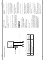
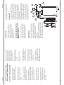
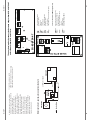
Head Office
Manitowoc Beverage Systems
Chancel Way, Halesowen
West Midlands, B62 8SE, UK
Tel: +44.121.501.2566
Fax: +44.121.500.0873
www.manitowocbeverage.com
[email protected]
2011 Manitowoc
continuing product improvements may necessitate change of specification without notice.
BSEN61000-6-1:2001 Radiated and Immunity compatibility (EMC) – Generic standards.
BSEN61000-6-3:2001 Electromagnetic emissions compatibility (EMC)- Generic standards.
Household and Similar Electrical Appliances – Safety (particular requirements for
commercial refrigerating appliances with an incorporated or remote refrigerant
condensing unit or compressor)
BSEN 60335-1:2002 +A14:2010 – Refrigeration, Household Safety
BSEN 60335-2-89:2003 – Refrigeration, Motors and Pumps
The safety targets regarding the Low Voltage Directive 2006/95/EC according to the
following co-ordinated standards have been applied:
EC Declaration of Conformity
EC Guideline Electro Magnetic Compatibility 2004/108/EC
Machinery Directive 2006/42/EC has been fulfilled.
DATE: 24/10/11
CCOOL 7-02-01XX-XX
CCOOL 9-02-02 XX-XX
CCOOL 11-02-03 XX-XX
CCOOL 15-02-04 XX-XX
CCOOL 37-02-05 XX-XX
MANUAL PART No. P156910
MANUAL REVISION: Rev 1
PRODUCT CODE
USER, INSTALLATION &
MAINTENANCE MANUAL
Cooler Carbonators
cCool 7, 9, 11, 15, 37
FOR QUALIFIED ENGINEERS ONLY
Flow Diagram. . . . . . . . . . . . . . . . . . . . . . . . . . . . . . . . . . . . . . . . . . . . . . . . . . . . . . . . . . . . . . . . . . . . . . . . . .
FOR QUALIFIED ENGINEERS ONLY
Exploded drawing and spare parts of Glycol Module . . . . . . . . . . . . . . . . . . . . . . . . . . . . . . . . . . . . .
Exploded drawing and spare parts of Heat Dump. . . . . . . . . . . . . . . . . . . . . . . . . . . . . . . . . . . . . . . .
Exploded drawing and spare parts of cCool . . . . . . . . . . . . . . . . . . . . . . . . . . . . . . . . . . . . . . . . . . . . .
Installation instructions.. . . . . . . . . . . . . . . . . . . . . . . . . . . . . . . . . . . . . . .. . . . . . . . . . . . . . . . . . . . . . . . . .
Technical Data . . . . . . . . . . . . . . . . . . . . . . . . . . . . . . . . . . . . . . . . . . . . . . . . . . . . . . . . . . . . . . . . . . . . . . . . .
Safety Instructions . . . . . . . . . . . . . . . . . . . . . . . . . . . . . . . . . . . . . . . . . . . . . . . . . . . . . . . . . . . . . . . . . . . . .
Warning & Safety Instructions . . . . . . . . . . . . . . . . . . . . . . . . . . . . . . . . . . . . . . . . . . . . . . . .. . . . . . . . . .
2
FOR QUALIFIED ENGINEERS ONLY
Wiring Diagram . . . . . . . . . . . . . . . . . . . . . . . . . . . . . . . . . . . . . . . . . . . . . . . . . .. . . . . . . . . . . . . . . . . . . . . . .
SECTION 10
FOR QUALIFIED ENGINEERS ONLY
Fault Analysis . . . . . . . . . . . . . . . . . . . . . . . . . . . . . . . . . . . . . . . . . . . . . . . . . .. . . . . . . . . . . . . . . . . . . . . . . . . .
SECTION 11
FOR QUALIFIED ENGINEERS ONLY
User Manual Installation Still Water boost facility (activayed by pressure drop) . . . . . . . . . . . . .
SECTION 12
FOR QUALIFIED ENGINEERS ONLY
User Manual Installation Still Water boost facility (electrically activated). . . . . . . . . . . . . . . . . . . . .
SECTION 9
SECTION 8
SECTION 7
SECTION 6
SECTION 5
SECTION 4
SECTION 3
SECTION 2
SECTION 1
Please read the operating instructions carefully before operating this unit
45-55
37-43
30-36
29
28
27
26
24-25
12-23
11
4-10
3-10
All Other brand names specified in this documentation refer to the appropriate companies or their products. Manitowoc
are not the owner of those brand names.
cCool is a brand of Manitowoc.
Reproduction of any kind without previously written permission of Manitowoc is not allowed.
Waterbath
area
C
earth
transformer
solenoid valve
agitator motor
compressor
carbonator
pump
recirc pump
L
Level electrodes
© 2004 Manitowoc. All rights reserved.
Ice bank
probes
max
gnd
min
13
14
14
S1
Ice
13
Machine area
Thermo
N PE
P
mains connector
Niveau
SG-83 0737
2
3
4
5
1
2
3
1
2
3
4
5
6
7
230V
230 V
Relais
230V
230 V
Relais
Min
Max
S
GND
Electrobox
Thermo contact
Fixed at the
housing
Dear Customer!
Please read these operating instructions carefully!
Examine the equipment immediately after supply for transport damage. Contact the manufacturer and/or carrier if
necessary. Damage, which arises by inappropriate treatment or operation, is not subject to guarantee.
Manitowoc constantly develop the products further according to their policies. Manitowoc reserve therefore the right, to
modify and to improve the products described in this documentation without previous announcement.
Fixed at the
housing
55
Section 12
SG-83-0401-H
SG-83-0009-H
Table of Contents
control
niveau
control
ice bank
54
Electrobox
HDP Aus
MV
24V 100 VA
HDP Ein
Press Hann Quer Therm
Solenoid
Valve
Section 12
High pressure
pump still water
to SG-83 0775 0500
Machnie area
blue
black
Pressure
switch
dispense
taps
CO2 lamp
brown
Warning
MANITOWOC AND ITS LEGAL
ENTITIES ENSURE NO LIABILITY FOR
DAMAGE CAUSED BY THE USE OF NON
GENUINE SPARE PARTS OR
BY IMPROPER TREATMENT OF THE
EQUIPMENT.
SAFETY INSTRUCTIONS
THE UNITS COMPLY WITH THE CURRENT
STANDARDS AND REGULATIONS OF THE EU
AND REPRESENT THE CURRENT STANDARD
OF TECHNOLOGY.
SAFETY DURING INSTALLATION, OPERATION
AND DECOMMISSIONING CAN ONLY BE
ENSURED BY FOLLOWING THE INSTRUCTIONS
IN THIS USER MANUAL.
ANY WORK OR MAINTENANCE MUST BE
CONDUCTED IN ACCORDANCE WITH THE
FOLLOWING SAFETY INSTRUCTIONS.
TECHNICAL CHANGES TO SAFETY OR
ELECTRICAL DEVICES OR THE MAINS LEAD
ARE STRICTLY FORBIDDEN. INSTALLATION,
MAINTENANCE AND REPAIR ON THIS
EQUIPMENT MUST BE CARRIED OUT
BY SUITABLY TRAINED PERSONNEL.
ONLY USE GENUINE SPARE PARTS.
NON-COMPLIANCE WITH THESE
INSTRUCTIONS MAY RESULT IN SERIOUS
INJURY OR DEATH.
Warning
3
SYSTEM PRESSURE
THE CARBONATOR IS AN INTEGRAL PART OF
THE UNIT AND IT SHOULD BE NOTED THAT
THE CARBONATION PROCESS INVOLVES THE
USE OF HIGH PRESSURES AND
POTENTIALLY NOXIOUS GAS AND AS SUCH
DUE CARE SHOULD BE TAKEN WHEN
HANDLING, INSTALLING AND MAINTAINING
THE EQUIPMENT WITH PARTICULAR
REGARD TO THESE HAZARDS.
Warning
WAYS THE EQUIPMENT SHOULD BE USED
THE UNITS ARE INTENDED FOR USE AS A
COOLING AND RECIRCULATION UNIT FOR
SYRUPS AND CARBONATED WATER TO
PROVIDE THE CORRECT CONDITIONING FOR
SERVING DRAUGHT SOFT DRINKS AND AS
SUCH SHOULD ONLY BE USED FOR THAT
PURPOSE. THERE ARE NO OTHER
RECOMMENDED USES FOR THIS EQUIPMENT.
Section 1
Warning
4
All mains voltage components are hazardous.
Any electrical work must be carried out by a
qualified competent person.
c) The wire which is coloured Brown MUST be
connected to the Terminal in the Plug that is
marked with the letter‚ L™ or coloured Red.
b) The wire which is coloured Blue MUST be
connected to the Terminal in the Plug that is
marked with the letter‚ N™ or coloured Black.
a) The wire which is coloured Green and Yellow
MUST be connected to the terminal in the Plug
that is marked with the letter‚ E™ or by the earth
symbol coloured Green or Green and Yellow.
As the Colours of the Wires in the Mains Lead
of this Appliance may not correspond with the
Coloured Markings identifying the Terminals in
the Plug to be fitted, proceed as follows:
Green and Yellow.............Earth
Blue .......................................Neutral
Brown...................................Live
WARNING:THIS EQUIPMENT MUST
BE EARTHED
THE WIRES IN THIS MAINS LEAD ARE
COLOURED IN ACCORDANCE WITH THE
FOLLOWING CODE:
Warning
Warning
This information should be displayed in a position
adjacent to the CO2 supply cylinder at all times.
4. ALWAYS Secure cylinder upright
whilst in use.
5. ALWAYS Keep cylinder away
from heat.
6. NEVER Drop or throw cylinders.
7. NEVER Try to unscrew fittings
from containers.
8. ALWAYS Ventilate area after CO2 leakage.
1. ALWAYS Connect the CO2 or
gas cylinder to a REDUCING VALVE.
2. NEVER Try to connect cylinder
directly to product container.
3. NEVER Interconnect soft drinks, CO2
or gas cylinder equipment
with other equipment.
CARBON DIOXIDE
Warning
A) SWITCH OFF THE SOCKET THAT THE PLUG
IS INSTALLED IN TO.
B) REMOVE THE PLUG FROM THE SOCKET.
C) A HEAT DUMP IS INCLUDED WITH ALL
WATER COOLED UNITS. THE
CONNECTING PLUG SHOULD BE REMOVED
FROM THE GLYCOL MODULE.
BEFORE COMMENCING ANY
WORK/MAINTENANCE -
POWER ISOLATION METHOD
ALL UNITS ARE FITTED WITH A SINGLE PHASE
3 PIN 13 AMP PLUG. THE CCOOL 7, 9 AND
11 ARE FITTED WITH A 10 AMP FUSE, THE
CCOOL 15 AND 37. WITH A 13 AMP FUSE.
ALTERNATIVELY, A STANDARD EURO PLUG TO
IEC83:1975.
Tap banks
connection
with electric
lead in python
Cooler
CARBON DIOXIDE
CARBON DIOXIDE LEAKS ARE POTENTIALLY
FATAL IF CONCENTRATIONS RISE TO
DANGEROUS LEVELS, IN VIEW OF THIS, THE
INSTALLATION SHOULD BE REGULARLY
CHECKED FOR INTEGRITY AND THE GENERAL
AREA OF INSTALLATION PROPERLY
VENTILATED AT ALL TIMES.
Still
still water control
electric
Section 1
Hahn
Transformer
Still
electric
lead
installation in
pyhton
24V
53
Section 12
Soda
CO2
warning
lamp
Soda
230V
CO2 pressure
switch
52
To the taps
Stecker entfernen
Pressure switch still water
SG-83-0754-47
Agitator Compresssor Soda
Trans- M-valve
former
SG-83-0775-10
MV
Hahn Quer Thermo
24 VAC
REL OUT
24 VAC OUT
24 VAC IN
Transformer
230V / 24V
Connection of the still water boards when using the "CO2 empty" warning device
Carbon. Ice Thermo
HDP AUS Press
(connection between adapter board SG-83-0754-47, still water board SG-83-0775-10
and still water board SG-83-0775-0500)
HDP EIN
Circulation
7. ELECTRIC CIRCUITS
Section 12
SG-83- 0775- 0500
SHARP EDGES
MANITOWOC TRY TO AVOID ANY SHARP
EDGES. BASED ON THE METHODS OF
PRODUCTION AND THE MATERIAL USED
THIS CAN NOT ALWAYS BE GUARANTEED.
THEREFORE HANDLE THE UNIT WITH CARE TO
AVOID POSSIBLE CUTS.
Warning
HEAT
THE COMPRESSOR, CONDENSER, HIGH
PRESSURE REFRIGERATION TUBES AND
MOTORS WILL BECOME HOT DURING
OPERATION. PLEASE AVOID ANY CONTACT
TO THESE PARTS DURING AND AFTER
OPERATION UNTIL THEY HAVE
COOLED DOWN.
Warning
ROTATING PARTS
SOME COMPONENTS WILL ROTATE FOR
A SHORT PERIOD AFTER THE POWER TO
THE UNIT HAS BEEN SWITCHED OFF. THESE
COMPONENTS SHOULD BE AVOIDED UNTIL
STATIONARY.
Warning
Warning
5
THIS APPLIANCE IS NOT INTENDED FOR USE
BY PERSONS (INCLUDING CHILDREN) WITH
REDUCED PHYSICAL, SENSORY OR MENTAL
CAPABILITIES, OR LACK OF
EXPERIENCE AND KNOWLEDGE, UNLESS
THEY HAVE BEEN GIVEN SUPERVISION OR
INSTRUCTION CONCERNING USE OF THE
APPLIANCE BY A PERSON RESPONSIBLE FOR
THEIR SAFETY.CHILDREN SHOULD BE
SUPERVISED TO ENSURE THAT THEY DO
NOT PLAY WITH THE APPLIANCE.
Warning
IMPORTANT
PUMP PRESSURE TO THE CARBONATOR BOWL
CAN REACH 13.6 BAR (200PSI).
THIS EQUIPMENT CAN CONTRIBUTE TO AN
INCREASE IN THE AMBIENT TEMPERATURE.
Warning
DANGER BY LOW TEMPERATURES
THE EVAPORATION TEMPERATURE IN THE
HERMETIC CIRCUIT CAN ACHIEVE EASILY
-10°C. WITHOUT TAKING PREVENTIVE STEPS
THIS CAN BE A POTENTIAL SOURCE OF
ACCIDENTS WHILST CLEANING OR
MAINTENANCE OF PARTS AT SUCH
TEMPERATURES.
Section 1
48 kg (Dry)
46 kg (Dry)
75 kg (Dry)
73 kg (Dry)
79 kg (Dry)
77 kg (Dry)
92 kg (Dry)
90 kg (Dry)
145 kg (Dry)
145 kg (Dry)
13 kg (Dry)
9 kg (Dry)
6
ONLY LIFT THIS EQUIPMENT IN IT’S DRY STATE
Warning
cCool 7 Integral
cCool 7 Water Cooled
cCool 9 Integral
cCool 9 Water Cooled
cCool 11 Integral
cCool 11 Water Cooled
cCool 15 I ntegral
cCool 15 Water Cooled
cCool 37 Integral
cCool 37 Water cooled
GLYCOL MODULE
HEAT DUMP
UNIT WEIGHTS
cCool 37
The weights of this unit is such that
other than moving it across flat ground
(which is facilitated by integral castors /
wheels) a mechanical lifting device
should be used.
cCool 7,9, 11 & 15
The weight of these units is such
that other than moving it across
flat ground (which is facilitated by
integral castors / wheels option) or
lifting to a relatively safe height of
12” utilising two people, a mechanical
lifting device should be used.
CORRECT SAFE HANDLING
Warning
NOTE: THERE ARE NO USER
SERVICEABLE PARTS
ADJUSTMENT / MAINTENANCE
REQUIREMENTS
IT IS NOT RECOMMENDED THAT THE END
USER MAKES ANY ADJUSTMENTS OR
CARRIES OUT ANY MAINTENANCE OTHER
THAN: CHECK THE MAINS LEAD AND PLUG
VISUALLY FOR CONDITION.
CHECK THE UNIT AND ITS PIPEWORK FOR
EVIDENCE OF LEAKS VISUALLY, INCLUDING
THE HEAT DUMP.
CHECK THAT THE CONDENSER GRILL AND
VENTS ARE NOT CHOKED OR OBSCURED,
INCLUDING THE HEAT DUMP.
IF THERE IS ANY SPILLAGE OF LIQUID ONTO
THE UNIT, ISOLATE THE POWER SUPPLY
BEFORE CLEANING UP. MAKE ANY
NECESSARY ADJUSTMENTS AS
RECOMMENDED BY THE SYRUP SUPPLIER.
Evaluator electronics
24 VAC Rel OUT
6. OPERATING PRINCIPLE (SG-83-0775-0500)
24 VAC IN
Section 1
24 VAC OUT
51
Section 12
50
Designation
Still water board for electrical actuation
Supply voltage lead for STWE
Supply voltage lead for taps
Connection lead to still water control
(controlled by reduction in pressure
(SG-83-0775-10)
No.
1
2
3
4
Spare parts list
Item No. SG-86-0824-20
Item No. SG-86-0824
24 VAC IN
SG-83-0775-0500
5. DRAWING WITH SPARE PARTS LIST
24 VAC OUT
Section 12
24 VAC Rel OUT
SG-83 0775 0500
SG-86-0824
SG-86-0824-20
SG-86-0922
Item No.
Item No. SG-86-0922
Clean and sanitize the cooling coils and
product lines using a proprietary
cleanser/sanitizer of the Alkaline Hypochlorite type,
in accordance with the manufacturer’s recommendations. MBS recommends the use of “Pipeline” beer
line cleaner, which changes colour according to the
condition of the product lines. It is available from
beer and soft drinks wholesalers, or direct from:
Chemisphere UK Ltd, 143-149 Bath Road,
Kettering, Northants NN16 8NE.
See above for detailed cleaning instructions
IMPORTANT: Do Not Use A Water
Or Steam Hose To Clean The Unit
Whilst Still Installed.
IMPORTANT: Personal Protective
Equipment Should Always Be Used.
IMPORTANT: Persons performing
Cleansing /Sanitizing operations MUST be
competent and fully trained in safe methods
of use of Cleansing / Sanitizing Agents
and their applications.
RECOMMENDED LINE
CLEANING METHOD
It is important that all the vents and grills are kept
clear (including condenser grills where applicable)
otherwise cooling performance decreases and the
system overheats.
Do not use a water or steam hose to clean the unit
whilst still installed.
Personal protective equipment should always
be used.
NOTE:
Persons performing Cleansing/Sanitizing operations
MUST be competent and fully trained in safe methods of use of Cleansing/Sanitizing Agents and
their applications.
METHODS OF CLEANING
7
ANNUALLY:
By a competent service / maintenance engineer.
Isolate unit from mains electricity supply. Remove
any extraneous debris from the unit or its casing
preferably using a vacuum cleaner or brush,
including the heat dump. Check unit for
electrical safety.
9. The lines are now clean, safe and ready for
reconnection to the product. Reconnect the
Keg in the storage/cellar area and pull
Product through to the tap.
8. Disconnect the line cleaning solution
and draw fresh water through the system.
Dispense some water into a glass or other
clear vessel and check that there is no
purple colour remaining. If necessary, draw
more clean water through the system until
the run-off is clear.
7. The purple colour denotes lines which are
clean and free from contamination.
6. Repeat stages 4 and 5 twice, or until the
run-off is purple in colour.
5. Close the tap and leave for 10 minutes.
4. Draw the line cleaning solution through
the dispense tap. If the lines are particularly
contaminated with yeast or bacterial growth,
the run-off will be green/grey/black.
3. Connect the line cleaning solution to
the lines to be cleaned.
2. Mix the beer line cleaner with clean water,
in the ratio specified in the instructions
[typically 1 capful per 4.5 litres (gallon)].
The solution will be purple in colour. NOTE:
use the appropriate personal protective
equipment, to avoid splash burns or
damage to eyes from splashes.
1. Draw clean water through the system until it
all traces of product have disappeared.
Cleaning instructions for “Pipeline” beer
line cleaner:
Section 1
8
5. Isolate from heat dump (coolant lines)
using service valve.
4. Vent pressure lines by opening
dispense tap.
3. Isolate product supply from unit.
2. Disconnect the heat dump power cable.
1. Isolate the unit from mains
electricity supply.
In the event of freezing up occurring the following
action is recommended:
Note: A 30% glycol mixture is suitable for operation
in temperatures as low as 12˚c.
For operation in temperatures as low as -25˚c, a 50%
glycol mixture is required.
It should be noted that heat dumps may
require to be sited where freezing may occur which
is why a 30% glycol \ water mixture is used as a
coolant. Failure to adhere to this recommendation
could result in damaging consequences. The
concentration of the coolant should not be
compromised, and in the event of spillage, the lost
volume should be replenished with the
correct mixture.
7. Check for obvious leaks.
It is recommended that the unit is sited In such a
way as not to expose it to temperatures likely to
cause freezing i.e. below 0°C. If the unit is to be
sited in an unheated area insulate all pipework
and provide some form of emergency heating
which should be controlled by a frost thermostat
sited in close proximity to the unit.
11. Observe unit running for a short
period watching out for leaks,
strange noises or any other form
of malfunction. If no problems are
observed then normal operation
of the unit may be resumed.
10. Reconnect mains electricity
supply and heat dump supply.
9. Reconnect product supply.
8. Turn water supply on whilst
continually watching for leaks.
6. Apply gentle warmth to the general
area of the unit and its pipework.
PREVENTION OF FREEZING / ACTION REQUIRED
IF FREEZING OCCURS
Section 1
Type of fault
Carbonator pump motor
fails to start when still
water is drawn .
Cause
Electronics (STWE)
fail to energise the
motor
4. FAULTS AND THEIR CORRECTION
49
correction
Check whether all electric
leads from the STWE are
properly connected.
Check whether the lead for
the carbonator motor is
connected.
Replace the electronics.
Section 12
48
HDP Aus
MV
HDP Ein
Press
Hahn
Quer
Thermo
8. Unplug the mains plug of the appliance in which
the STWE is to be installed.
9. Open the cover of the cooler.
10. Remove the plug-in connection for the still
water low-pressure, pressure switch from the
still water board SG83-0775-10
Installation of the electronics must be undertaken
by a properly qualified service technician.
INPUTS:
3. COMMISSIONING (RETROFITTING)
Section 12
SG-83 -0775 -10
11. Secure the still water board SG-83-0775-0500
(STWE) in the appliance by means of
screws.
12. Make the necessary electrical connections
(see item 7 of these instructions):
Supply voltage lead for STWE:
[STWE => 24VAC]
Supply voltage lead for taps:
[STWE => connection lead for the taps
in the python]
connection lead to still water control
(controlled by reduction in pressure)
SG-83-0775-10:
[STWE => still water control pressure
drop SG-83-0775-10.
13. Close the cover of the appliance again.
14. Plug in the mains plug again.
1. Isolate the unit from mains electricity supply and
the mains water supply.
2. Drain off all post mix products including the syrup
and carbonated water (clean syrup lines as
recommended by the syrup supplier).
3. Turn the CO2 off and disconnect all lines associated
with the regulator, also vent pressure from lines by
purging the product valves as required.
4. Disconnect all post mix pipework and remove
dispense head equipment, including the python,
and remove as recommended by the
equipment owner.
5. Siphon or pump out water from the waterbath to
a suitable drainage point.
6. Allow ice bank to melt (the careful use of hot water
may be used to accelerate this process). Remove
any remaining water from melting the ice.
7. Drain all the glycol \ water from water cooled units
into a suitable container and dispose of it in
accordance with the instructions given by the
dispense equipment owner.
DISMANTLING / DECOMMISSIONING PROCEDURE
Minimum 75 PSI (5.1 BAR)
Maximum 90 PSI (6.2 BAR)
MAX. / MIN. CO2 PRESSURES
Minimum 20 PSI (1.4 BAR)
Maximum 60 PSI (4.1 BAR)
MAX. / MIN. WATER PRESSURES
COOLER UNIT:
Minimum +5°C Maximum +40°C
HEAT DUMP UNIT:
Minimum -25°C Maximum +40°C
(with a 50% glycol mixture)
MAX. / MIN. AMBIENT TEMPERATURES
9
Section 1
10
IMPORTANT:
FAILURE TO REMOVE ALL ICE / WATER COULD
RESULT IN SUBSTANTIAL AMOUNTS OF
WATER BEING RELEASED FROM THE UNIT
WHICH MAY BE DETRIMENTAL TO THE UNIT
AND/OR ITS SURROUNDINGS AND INCREASE
THE MAXIMUM WEIGHT OF THE UNIT.
Section 1
WHEN ASSEMBLING AND INSTALLING THE STILL
WATER CONTROL, PLEASE OBSERVE THE SAFETY
INSTRUCTIONS INCLUDED IN THE OPERATING
INSTRUCTIONS FOR THE APPLIANCE
Warning
The board is installed in a casing. It is possible
to secure the casing by means of a screw.
The board with its own supply current of 24V AC
also supplies external taps. Supply to the taps is
assured via the leads laid in the insulated pipes
(the “python”) where for all still water valves to
be controlled two leads are needed altogether.
The cross-section of the lead laid in the python
must be borne in mind here. If one of the
external valves is operated, a current will flow
via the board. This is measured, and as soon as it
exceeds a value of 500 mA, an additional 24V AC
will be switched to the still water board
SG-83-0775-10. This voltage actuates the still
water board SG-83-0775-10. The board is an
additional module and is installed in the cooler.
The still water board SG-83-0775-10 already
used by us has an added function. This is to
detect the actuation of an external valve. If this
is detected, a 24V AC current is applied to the
still water board SG-83-0775-10 already used,
which in turn switches on the still water pump
and keeps it in operation until the valve is no
longer being actuated.
500 mA +/- 25%
400 mA +/- 25%
47
These distances are based on simultaneous
operation of four valves, each taking 1.5 amps.
The maximum distance between the valve and
STWE: a cable cross-section area of
0.75mm² : 15 metres at 24V AC.
with a cable cross-section area of
1.5mm² : 35 metres at 24V AC.
The still water boost facility for electrical actuation
(STWE) is installed in the cooler. The
installation instructions for the respective
cooler must be observed.
ON:
OFF:
SWITCHING THRESHOLDS:
• 2 x contacts for supplying the external valves
with 24 VAC max. 8 amps.
• 2 x contacts for supplying the relay (Finder 40.31)
on the board SG-83-0755-10 (still water board).
OUTPUTS:
• 2 x contacts for input voltage 24 VAC (+10%, -30%).
INPUTS:
2. ELECTRICAL CONNECTIONS
SG-86-0824
SG-86-0824-20
SG-86-0922
SG-83-0775-10
SG-83-0775-0500
1. FUNCTION OF THE STILL WATER
BOOST FACILITY
Still water boost facility (electric)
Leads:
Supply voltage for STWE
Supply voltage for valves
Connection lead to the still water control
Order Numbers
Section 12
CONTENTS STILL WATER BOOST FACILITY
46
SECTION 12
FOR QUALIFIED ENGINEERS ONLY
User Manual Installation Still Water boost facility (activated by pressure drop) . . . . . . . . . . . . . . . .
1. Function of the Still Water Boost Facility. . . . . . . . . . . . . . . . . . . . . . . . . . . . . . . . . . . . . . . . . . . . . . . . . . ..
2. Electrical Connections . . . . . . . . . . . . . . . . . . . . . . . . . . . . . . . . . . . . . . . . . . . . . . . . . . .. . . .. . . . . . . . . .. . . .
3. Commissioning (Retrofitting) . . . . . . . . . . . . . . . . . . . . . . . . . . . . . . . . . . . . . . . . . . . . . . . . . . . . . . . . . . . . .
4. Faults and their correction. . . . . . . . . . . . . . . . . . . . . . . . . . . . . . . . . . . . . . . . . . . . . . . . . . . . . . . . . . . . . . . .
5. Drawings with spare parts list . . . . . . . . . . . . . . . . . . . . . . . . . . . . . . . . . . . . . . . . . . . . . . . . . . . . . . . . . . . .
6. Operating principle of the still water board . . . . . . . . . . . . . . . . . . . . . . . . . . . . . . . . . . . . . . . . . . . . . . .
7. Electric circuits - wiring diagram. . . . . . . . . . . . . . . . . . . . . . . . . . . . . . . . . . . . . . . . . . . . . . . . . . . . . . . . . .
Section 12
45-55
47
47
48
49
50
51
52-55
13 kg (dry)
R134a
R134a
375g
375g
275g
275g
38 litres
51 litres
13,2 kg
20 kg
560mm
590mm
480mm
510mm
700mm
750mm
430mm
460mm
75 kg
79 kg
9 kg (dry)
R134a
200g
N/A
17,5 litres
7 kg
610mm
400mm
525mm
355mm
48 kg
230V / 50Hz
230V / 60Hz
1200W
SC18 G
18cm3
33
(2/3HP)
Danfoss
684W
230V / 50Hz
230V / 60Hz
1000W
SC12 G
12cm3
33
(3/8HP)
Danfoss
464W
cCool 11
230V / 50Hz
230V / 60Hz
1000W
SC12 G
12cm3
(3/8HP)
Danfoss
464W
cCool 9
R134a
425g
275g
65 litres
25 kg
630mm
550mm
865mm
535mm
92 kg
230V / 60Hz
230V / 50Hz
1300W
SC 21 G
21cm3
33
(4/5HP)
Danfoss
793W
cCool 15
R134a
1100g
800g
114 litres
50 kg
830mm
670mm
1100mm
625mm
145 kg
230V / 50Hz
230V / 60Hz
1650W
CAJ4511
33cm3
33
(1 1/3HP)
L’Unite
1252W
cCool 37
H2
D
W
H1
(1) at evaporation temp. t 0 =-10°C , condensing temp. tc = 55°C and ambient temp. ta = 32°C
Cooling
capacity(1)
Refrigerant
Integral
W/cooled
Water Bath
Ice-Bank Size
Height H1
Height H2
Width W
Depth D
Weight (dry)
Heat Dump
Weight
Glycol Module
Weight
Input Power
Compressor
Electr. Power
cCool 7
Technical Data
11
Section 3
6. Connect all products to the unit as
labelled (do not connect to the syrup
containers yet).
NOTE:
Sealed plugs may be fitted to new units.
Integral & Water Cooled -10 AMP FUSE
Integral & Water Cooled -10 AMP FUSE
Integral & Water Cooled -10 AMP FUSE
Integral & Water Cooled - 13 AMP FUSE
Integral & Water Cooled - 13 AMP FUSE
12
3. If the unit is a water cooled version, the glycol
module and heat dump must be installed and
connected as detailed in the GLYCOL MODULE
AND HEAT DUMP INSTALLATION INSTRUCTIONS
on pages 14-23 in this manual before
commissioning the complete system.
cCool 7
cCool 9
cCool 11
cCool 15
cCool 37
Fuses for standard UK plug:
2. Site the unit in a convenient location in
the cellar or room on a level surface where it is to
be located and make sure that a mains
electricity supply is within 2 meters and in an
area allowing free circulation of air. The
unit should be fitted with a correctly fused and
wired 13 amp plug fitted with the correct fuse
as below or alternatively a standard Euro Plug to
IEC83:1975.
1. Unpack the unit from its transportation packing
and visually check for any signs of damage.
Note: If the unit is a version that only has
a single power on switch, unplug the care
pump and soda pump connections from
the distribution board.
13. Ensure that the soda recirculation pump
and carbonator pump are switched off.
12. Check for obvious leaks and rectify
before proceeding any further.
11. Turn on the mains water supply.
10. Remove the top cover and turn on
the CO2 supply and vent the
carbonator bowl using the relief valve
located on the top of the bowl.
Additionally, operate the dispense
valve until the air in the python lines
is purged.
9. Connect the unit to the mains
electricity supply (do not turn on yet).
8. Fill the water bath with fresh clean
COLD water until the overflow level
is reached.
7. Connect CO2 gas supply of 5 bar to 6.3
bar to the cooler using the tube labelled
‘CO2 IN’ (do not turn on yet).
5. Connect a mains water supply of 2.5 bar
to 4 bar to the tube labelled ‘WATER IN’
(do not turn on yet).
NOTE:
The unit should be installed and serviced by a
suitably trained person.
cCOOL SODA CIRCUIT COOLER RANGE
INSTALLATION INSTRUCTIONS FOR
INTEGRAL & WATER COOLED UNITS
4. Connect the dispense head to the unit
using suitable fittings and python,
refering to the connection diagram on
the lid of the cooler and those
supplied with the dispense head.
INSTALLATION INSTRUCTIONS
Section 4
STWE
Still water boost facility
(electrically activated)
USER MANUAL
INSTALLATION & SERVICE
44
Section 12
21. The dispense head can now be brixed
and the system will be ready to use.
20. Refit the top cover to the base unit.
19. Connect the syrup containers and
operate dispense valves until syrup is
dispensed.
18. Switch on/re-connect the soda pump.
17. Prime the dispense head by operating
the valves and ensure all pockets of CO2
are removed from system.
16. Switch/on reconnect the carbonator pump
and allow the carb bowl to fill until the pump
cuts out.
15. If the unit is a water cooled version, ensure
that the glycol lines prime correctly and that
the glycol module is topped up
to the correct level.
14. Switch on the unit at the mains power
supply and allow ice bank to build. Mains
plug must be accessible.
13
Section 4
14
6. The heat dump must be connected
using a minimum of 1.5mm two
core cable. If a smaller cable is used,
a voltage drop will occur which may
cause the fan motor to run at a
reduced speed.
5. Do not exceed the recommended
distance and lift from the base unit to
the heat dump of 9m lift, 40m run.
4. Use the recommended tubing
(15mm O/D, 10mm I/D Special EVA) to
connect the base unit to the heat dump.
Do not use PVC braided tube, as this
is not compatible with glycol and will
degrade over a period of time.
3. Ensure there are no other heat sources,
i.e. a condensing unit or another heat
dump, in the immediate vicinity, where
hot air may be re-circulating.
2. Ensure the unit is sited on an outside
wall (preferably non south facing) in
the correct orientation out of direct
sunlight.
1. It is important that the heat dump is
sited correctly to enable it to work
efficiently. The guidelines below
should be adhered to wherever possible.
HEAT DUMP - GENERAL GUIDELINES
HEAT DUMP AND GLYCOL MODULE
INSTALLATION – WATER COOLED UNITS
Section 4
12. To enable the heat dump to be
mounted on a flat surface, a floor
standing mounting kit is available
as an option.
(Order part number 09-0203-01).
11. Ensure that the heat exchanger
matrix of the heat dump is kept
clean and free from obstructions.
It is recommended that it should
be cleaned with a soft brush at
regular intervals.
10. The flow and return lines must
not be strapped together, as heat
transfer between the two will
effect the system performance.
9. Do not insulate the flow and
return lines.
8. Do not kink the flow and return
tubes which would restrict the
coolant flow.
7. If the unit is to be installed inside
a building or room, ensure that
there is adequate ventilation
within the room to enable the
heat to be dissipated effectively.
Temperatures within the room
should not exceed 40°C
1
Still water side:
After the t-piece (3), the water firstly passes
through the non-return valve (11) followed by
the pressure reducing valve (7) which is set at
4.4 bar (dynamic). Pressure is then measured
at the low-pressure switch (8), which should
Mains water is is entering pump (1) with a
dynamic pressure of 2 to 2.5 bar, where it’s
pressure is boosted to about 10 bar. It then
passes through the pre-chilling coil (2) and
gets split at the t-piece (3) into the:
6. FLOW DIAGRAM
The connection from the adapter board
(connection “carbonator pump”) and the
still water control (connection “carbonator
pump on”) delivers the required voltage
for supplying the carbonator bowl.
THE THERMO-CONTACT MUST BE
CONNECTED TO THE STILL WATER
BOARD 56-83-0775-10.
The still water board is operated with
230 volts mains supply. The mains power
is supplied via the connection between
the adapter board (connection “Temp”)
and the connection “Quer” on
the still watercontrol.
5. POWER SUPPLY
2
3
6
4
11
7
5
8
43
9
10
Soda-water side:
After the t-piece (3), the water passes the
solenoid valve (4), which is normally closed
and should have an orifice of at least 2.5mm.
It then flows through the double non-return
valve (5) to the carbonator bowl (6), where
the high pressure jet of water entering the
carbonator bowl becomes saturated with
CO2. Following this, the soda water flows to
the post-mix valve (10).
If the pressure switch (8) is requesting still water, (the still water valve is open and the pressure drops below 4 bar) then pump (1) will
operate. If at the same time the carbonator
level control calls for the carbonator bowl to
be replenished, the solenoid valve (4) opens
and water is diverted at the t-piece (3) to both
the still water and the soda water side.
cut-in at a pressure of 4 bar (the pre-set cutout point is 4.5 bar). Following this, still water
flows to the post-mix valve (9).
Section 11
42
Level electrodes
Waterbath
area
C
L
earth
transformer
solenoid valve
agitator motor
compressor
carbonator
pump
max
gnd
min
13
14
14
S1
Ice
13
Machine area
Thermo
N PE
P
mains connector
Niveau
83 0737
recirc pump
Ice bank
probes
Hahn Quer
MV
Press
HDPAus
2
3
High pressure
Electrobox
Fixed at the
housing
Thermo contact
Fixed at the Pressure switch
still water
housing
4. WIRING DIAGRAM
pump still water
Section 11
Solenoid Valve
HDP Ein
Therm
5m
15m
20m
30m
40m
DISTANCE FROM
BASE UNIT
TO HEAT DUMP
NOTE: Maximum Lift = 9m
5. Again using Cobracol tubing
connect the ‘COOLANT OUT’ from
the base unit to the ‘FLOW’ on the
heat dump. Connect the ‘RETURN’
on heat dump to the ‘COOLANT
RETURN’ on the glycol module to
complete the circuit.
4.25 ltr
4.50 ltr
4.75 ltr
5.00 ltr
5.40 ltr
8.25 ltr
9.00 ltr
9.25 ltr
10.00 ltr
10.60 ltr
15
APPROX. VOLUME
OF WATER
Maximum Run = 40m
Alternatively, if the unit only has a power on
switch, unplug the compressor plug from the
distribution board.
9. On the base unit, locate the
compressor switch and ensure
that it is in the ‘OFF’ position. This
will aid with priming of the
cooling system.
NOTE: a 30% glycol mixture is suitable for
operation in temperatures as low as -12˚c.
For operation in temperatures as low as
-25˚c, a 50% glycol mixture is required. In the
event of freezing up occurring the following
action is recommended:
8. Fill the glycol module reservoir
tank with a quantity of coolant
mixed 30% glycol to 70% water,
ensuring a quantity remains for
topping up the system
when priming.
7. Ensure the lines are correct and
secured neatly and free from kinks.
6. Finally, connect the 1.5mm twin
wire coming from the heat dump to
the 24V outlet socket on the glycol
module using the two pin plug supplied
with the glycol module. It does not matter
which way the wires are connected as they
are not polarised.
APPROX. VOLUME
OF GLYCOL
4. Install the heat dump as described on
pages 14-23.
3. Using Cobracol tubing, connect the
‘COOLANT FLOW’ from the glycol
module to the ‘COOLANT IN’ on the
base unit.
2. Connect the glycol module’s power
supply to the 240V power outlet socket
on the base unit.
(DO NOT SWITCH ON YET)
1. Site the glycol pump module within
2 meters of the base unit and use the
bracket supplied to secure the module
to a wall. Alternatively, position the unit on
a flat level surface.
NOTE: The unit should be installed and serviced by
a suitably trained person.
GLYCOL MODULE INSTALLATION
INSTRUCTIONS
Section 4
16
Coolant Flow
HEAT DUMP
GLYCOL
MODULE
24V Supply
230V Supply
230V Mains Supply
BASE UNIT
11. Switch the compressor switch
to ‘ON’ and re-connect the compressor plug
and finish the installation up to point 21.
Water cooled unit - equipment connection schematic
10. Refer back to the base unit installation
instructions on page 12 and complete the
installation up to point 14. Upon
switching the unit on, the pump in
the glycol module will start together
with the heat dump fan, the refrigeration
remaining off. As the system primes,
the level will drop in the coolant header
tank. Keep topping this up until the
system is full, there are no air locks
and that coolant is returning freely
into the header tank. If the system
trips out on the thermal switch whilst
priming, this will have to cool before
it automatically restarts.
Section 11
HDP
HDP
HDP Aus
MV
HDP Ein
Press
Hahn
Quer
Thermo
SG-83-0754-47
KLP
Thermo:
Quer:
Press:
HDP Aus:
Hahn:
KLP :
HDP:
Komp:
RW:
MV:
Trafo:
Karb:
Eis:
Temp:
komp
and still water board SG-83-0775-10.
MV
Trafo
Connection for carbonator pump
24 VAC connection from tap
(or SG-83-0775-0500)
Connection, pressure switch for
still water
Thermo-contact
Cross-link (Temp. / Quer)
41
HDP Ein: Connection from HDP (adapter board)
Soda recirculation pump
Carbonator pump
Compressor
Agitator
Solenoid valve
Transformer supply 230 V
Carbonator bowl
Ice-bank sensor
Temperature sensor for Carbonator pump
RW
3. Connections (make the connection between adapter board SG-83-0754-47
SG-83 0775 10
Section 4
Karb.
Eis
Temp
40
• Here, one carbonator pump supplies the
still water feed and the feed for the
carbonated drinks, the other exclusively
the feed for the carbonated drinks.
This means it is possible that only one
carbonator pump is in operation at a time,
when still water is being drawn. The
carbonator pump which supplies both
feeds must be connected to the still
water PCB. The other carbonator pump
is connected to the adapter board.
Operation with two carbonator pumps
• Here, the carbonator pump supplies
both the still water feed and the feed
for carbonated drinks. The carbonator
pump must be connected to the still
water control.
Operation with one carbonator pump.
Fundamentally, there are two possibilities:
2. FUNCTION OF THE CIRCUIT
Section 11
THE SYSTEM WILL RESET ITSELF, BUT IF THE
FAULT PERSISTS, IT SHOULD BE RECTIFIED
BEFORE FURTHER OPERATION.
1. LOW WATER/GLYCOL LEVEL.
2. COOLANT LEAK
3. BLOCKAGE WITHIN COOLING SYSTEM.
4. HEAT DUMP FAN FAILURE.
5. WATER PUMP FAILURE.
6. 24V TRANSFORMER FAILURE.
7. WIRING FAULT.
ALL WATER COOLED UNITS ARE FITTED WITH
AN AUTO RESET THERMAL SWITCH TO
PROTECT THE COMPRESSOR.
IF A FAULT OCCURS IT IS LIKELY TO BE ONE
OF THE FOLLOWING.
Warning
WAYS THE EQUIPMENT SHOULD BE USED
THIS UNIT IS INTENDED FOR USE IN
CONJUNCTION WITH COOLING UNITS
MANUFACTURED BY MANITOWOC. IT IS
DESIGNED TO BE CONNECTED AT THE
END OF THE WATER/GLYCOL RECIRCULATION
LINES AS MEANS OF REMOVING HEAT
FROM THE COOLING SYSTEM. THERE ARE
NO OTHER RECOMMENDED USES FOR
THIS UNIT.
Warning
17
4. With reference to the above drawing drill the
surface onto which the heat dump is to be
fitted at the stated mounting hole centers
ensuring that adequate clearance is allowed
around the heat dump to allow future access
for cleaning. The wall mounting bracket can
be used as a guide for marking its hole centers.
Ensure that the wall mounting bracket is
mounted squarely to ensure level movement
of the condenser matrix when fitted.
3. Remove the wall mounting bracket from the
assembly, (mounted on lift off hinges). Slacken
the two fixing screws securing the cover/fan
assembly to the condenser matrix, swing the
cover open and lift off the assembly.
2. Site the dump in a convenient location, preferably
in a non-heat sensitive and shaded area on the
outside of the building. If it cannot be installed
outside, ensure that the area is free from other
heat sources and is adequately ventilated to
prevent heat build up from the hot exhaust
air from the heat dump. In either situation the
heat dump should be sited to allow free circulation
of air. The maximum recommended height of
the heat dump above the cooler is 9 meters.
1. Unpack the unit from its transportation
packaging and visually inspect for signs
of damage.
NOTE: The unit should be installed and serviced
by a suitably trained person.
HEAT DUMP INSTALLATION INSTRUCTIONS
Section 4
18
4. With reference to the above drawing drill the surface onto
which the heat dump is to be fitted at the stated mounting
hole centers ensuring that adequate clearance is
allowed around the heat dump to allow future access
for cleaning. The wall mounting bracket can be used as a
guide for marking its hole centers. Ensure that the
wall mounting bracket is mounted squarely to ensure level
movement of the condenser matrix when fitted.
3. Remove the wall mounting bracket from the assembly,
(mounted on lift off hinges). Slacken the two fixing screws
securing the cover/fan assembly to the condenser matrix,
swing the cover open and lift off the assembly.
2. Site the dump in a convenient location, preferably in a
non-heat sensitive and shaded area on the outside of
the building. If it cannot be installed outside, ensure that
the area is free from other heat sources and is adequately
ventilated to prevent heat build up from the hot exhaust
air from the heat dump. In either situation the heat dump
should be sited to allow free circulation of air. The maximum
recommended height of the heat dump above the cooler
is 9 meters.
1. Unpack the unit from its transportation packaging and
visually inspect for signs of damage.
NOTE: The unit should be installed and serviced by a
suitably trained person.
HEAT DUMP INSTALLATION INSTRUCTIONS
WAYS THE EQUIPMENT SHOULD BE USED
THIS UNIT IS INTENDED FOR USE IN CONJUNCTION WITH
COOLING UNITS MANUFACTURED BY MANITOWOC. IT IS
DESIGNED TO BE CONNECTED AT THE END OF THE
WATER/GLYCOL RECIRCULATION LINES AS MEANS OF
REMOVING HEAT FROM THE COOLING SYSTEM. THERE
ARE NO OTHER RECOMMENDED USES FOR THIS UNIT.
Warning
Section 4
WHEN ASSEMBLING AND INSTALLING THE STILL
WATER BOOST FACILITY, PLEASE OBSERVE THE
SAFETY INSTRUCTIONS INCLUDED IN THE OPERATING
INSTRUCTIONS FOR THE APPLIANCE.
Warning
It is essential that the carbonator
pump for supplying the still water
feed is connected to the still water PCB,
otherwise trouble-free operation
cannot be guaranteed.
When a drink is dispensed on the still water side,
the water pressure falls at the monitoring pressure
switch, causing it to switch. This starts the
carbonator pump thus setting the required water
pressure for dispensing the still drink. In this
operating condition, filling of the carbonator bowl
is prevented. When dispensing of the still drink is
finished, pressure in the still water line increases
again and the pressure switch will cut out the
carbonator pump. If both still and carbonated
drinks are dispensed simultaneously, both feeds
are supplied from the carbonator pump.
The still water boost facility is an add-on PCB
and is used together with the adapter board
SG-83-0754-47 or SG-83-0754-31. Both boards
are located in the electric control box.
1. FUNCTION OF THE STILL
WATER BOOST FACILITY
39
Section 11
38
SECTION 12
FOR QUALIFIED ENGINEERS ONLY
User Manual Installation Still Water boost facility (activated by pressure drop) . . . . . . . . . . . . .
1. Function of still water boost facility . . . . . . . . . . . . . . . . . . . . . . . . . . . . . . . . . . . . . . . . . . . . . . . . . . .. . . .
2. Function of the circuit . . . . . . . . . . . . . . . . . . . . . . . . . . . . . . . . . . . . . . . . . . . . . . . . . . . . . . . . . . . . . . . . . . .
3. Connections. . . . . . . . . . . . . . . . . . . . . . . . . . . . . . . . . . . . . . . . . . . . . . . . . . . . . . . . . . . . . . . . . . . . . . . . . . . . .
4. Wiring Diagram . . . . . . . . . . . . . . . . . . . . . . . . . . . . . . . . . . . . . . . . . . . . . . . . . . . . . . . . . . . . . . . . . . . . . . . . .
5. Power Supply . . . . . . . . . . . . . . . . . . . . . . . . . . . . . . . . . . . . . . . . . . . . . . . . . . . . . . . . . . . . . . . . . . . . . . . . . . .
6. Flow chart . . . . . . . . . . . . . . . . . . . . . . . . . . . . . . . . . . . . . . . . . . . . . . . . . . . . . . . . . . . . . . . . . . . . . . . . . . . . . .
CONTENTS STILL WATER BOOST FACILITY
39-43
39
40
41
42
43
43
6. Connect the flow and return pipework
from the glycol module and base unit
to the fittings on the heat dump labeled
“FLOW” and “RETURN”. Secure the pipes
to the mounting surface so that the weight
of the pipes is not being carried on the heat
dump fittings. Do not kink the pipework
as this will restrict coolant flow. Do not insu
late the pipework. (pipework mounted on
an exterior surface may be insulated if it is
felt that due to extreme conditions freezing
may occur).
5. Either mark the position of the third
mounting screw at the time of marking
the wall mounting bracket position, or after
fitting the wall mounting bracket
hang the condenser matrix on, close against
the mounting surface and mark the
fixing position. The third fixing screw will
pass through the hole in the condenser
matrix. The retaining clamp is fitted over the
screw which can then be tightened to retain
the condenser matrix.
57.00cm
2.50cm
Mounting Holes
30.00cm From Wall
19
DRILLING POSITIONS FOR MOUNTING HOLES
30.00cm From Wall
MINIMUM DISTANCES FOR MOUNTING THE
HEAT DUMP FROM VERTICAL AND
HORIZONTAL SURFACES
Cover Assembly
Fixing Screws
Removable Wall
Mounting Bracket
13.00cm from Ceiling
With cover assemby
fully open, lift off
Section 4
250.00cm From Floor
Section 11
7.00cm
=
=
250.00cm
Fit Condenser Matrix
to Wall Mounting Bracket
20
Route 24V Supply Cable
Through Lower guide Tube
In Condenser Matrix
8. Ensure that the amount of cable entering
through the main cover is not excessive and
cannot become entangled in the fan blade.
Tighten the strain relief grommet to support
the cable. This should not be the only means
of support for the cable, therefore fix back to
the mounting surface at regular intervals
along the cable length.
Fix 24V Supply Cable
To Mounting Surface At
Regular Intervals
7. Route a twin core 24 volt supply cable
(1.5mm csa) through the lower guide tube
and then through the strain relief grommet
positioned below the two way terminal
block on the condenser matrix. The wires
are not polarised and may be fitted either
way round.
Rectangle Clamp
Close Condenser
Matrix Against
Mounting Surface
and Mark Fixing
Hole Position
Do not strap the flow and return pipes
together as heat transfer between the
two will effect the systems performance.
Section 4
STWE
Still water boost facility
(activated by pressure drop)
USER MANUAL
INSTALLATION & SERVICE
36
Allow the cooler to
produce a full ice bank
before dispensing
product
Switch Cooler on
No
No
Has the propellor come off
the agitator shaft
Yes
Is the Agitator motor
running
Yes
Check for recirculation at
the dispense head (cold
pipes, condensation
etc....)
Yes
Is the soda recirculation
pump working
Yes
Has the unit got an ice
bank
Yes
Yes
No
No
No
No
Replace propellor
See Agitator Motor
fault finding chart.
Possible air lock in
soda recirc lines.
Bleed out at the
dispense head,
reprime.
See Soda
Recirculation pump
fault finding chart
See refrigeration fault
finding chart.
Check the length and condition of the Python and installation in
general. If the python insulation is damaged or considered too thin
for the installation it will need to be replaced.
Check that the python does not exceed the run as stated in the
manual for the particular cooler. If it does the base unit must be sited
closer to the dispense head(s).
Check there are no external heat loads between the base unit and
the dispense head. (Python run in warm areas/ducting)
Check that the mains water temperature is not excesively high and
that the product is not stored in a high ambient area.
IS THE COOLER
SWITCHED ON
FAULT DIAGNOSIS FLOW CHART - PRODUCT TOO WARM
Section 10
Cable:1.5 mm sq., 2 core white PVC
covered (no earth) Insulation tubing:
3/8” or 1/2” ID.
CORRECT SAFE HANDLING
HANDLING OF THIS UNIT OFFERS NO SPECIFIC
HAZARD. UNIT WEIGHT 9 KGS (20LBS.) DRY.
POWER ISOLATION METHOD
1. SWITCH OFF THE SOCKET THAT THE BASE
COOLER UNIT IS INSTALLED INTO.
2. REMOVE THE PLUG FROM THE SOCKET.
21
Recommended - Pipework: 15mm OD x
10mm ID COBRACOL tubing.
10. Connect the wiring and the Pipework
to the cooler following the
instructions supplied with the cooler.
Ensure That Fan
Wiring is routed
through Retaining Clip
Note - Ensure that the wiring from the fan is
routed through the plastic clip provided to
prevent the possibility of the wires becoming
entangled in the fan blade.
9. After the condenser matrix is fully fitted to
the mounting surface, hang the cover/fan
assembly onto its hinges.
With the cover/fan assembly open, connect
the wires from the fan to the terminal block.
Section 4
22
NOTE: THERE ARE NO USER
SERVICEABLE PARTS.
1. Check the 24V Cable & Connections
visually for condition.
2. Check the unit and its pipework
for any evidence of leaks visually.
TWICE ANNUALLY: By a competent
service \ maintenance engineer
IT IS NOT RECOMMENDED THAT THE
END USER MAKES ANY
ADJUSTMENTS OR CARRIES OUT
ANY MAINTENANCE OTHER THAN :
It is important that all the vents and grills
are kept clear (including condenser grills
where applicable).
Do not use a water or stream hose to
clean the unit whilst still installed.
1. Isolate the unit from the Base Cooler
electricity supply.
2. Open the unit to access both sides
of the condenser matrix and remove
any extraneous debris from the unit
or its casing preferably using a
vacuum cleaner or brush.
3. Check unit for electrical safety.
Do not use a water or steam hose to
clean the unit whilst still installed.
Methods of cleaning
ADJUSTMENTS/MAINTENANCE
REQUIREMENTS
Section 4
Faulty
pump motor
Yes
Check for 240V
supply at
connection
Yes
Is the pump
plugged into its
mating connector
No
No
No
Yes
No
Is the glycol
mixture
recirculating
adequately
Yes
Re-site heat dump
closer to glycol
module.
Yes
Is the heat dump
sited more than
12m lift away from
the glycol module
No
Is the glycol
mixture
recirculating
adequately
Possible air lock in
system. Bleed air
lock out of system
and re-prime
No
Are the glycol
lines connecting
the heat dump
blocked, collapsed
or restricted in any
way.
Yes
Are the shut off
valves open on
the connections to
the pump
Is the glycol level
in the header tank
between Max and
Min marks
Top up to
maximum level
and check for leaks
No
Ensure tubing is the correct type
(Cobracol) and ensure pipes are
not secured together and are
away from heat sources
Internal wiring
fault or faulty
electrical feed
from base unit
Plug pump into
connector
IS THE GLYCOL
PUMP
OPERATING
No
Yes
Yes
No
Yes
Faulty pump
System O.K
Clear blockage or
restriction
Open shut off
valves
System O.K
FAULT DIAGNOSIS FLOW CHART - GLYCOL MODULE (WATER COOLED UNITS)
35
Section 10
34
Yes
Check for 240V on
input to
transformer
Internal wiring
fault or power
supply problem
from base unit
No
Yes
Yes
Yes
Check for 24V
output at
transformer in
glycol module
No
Check for 24V
supply at the
socket on the
glycol module
No
Is there 24V at
the heat dump
No
Replace
transformer
Internal wiring
fault between
transformer and
socket
Broken wire
between glycol
module and heat
dump
Replace fan motor
Is heat dump fan
running
Refer to Glycol Pump fault
guide
No
Is the glycol recirculating
adequately
No
Is the heat dump sited in
full sunlight or near other
heat sources without
adequate ventilation
No
Is the condenser matrix
blocked with debris
Yes
Yes
Yes
Re site heat dump
Clean radiator
matrix
FAULT DIAGNOSIS FLOW CHART - HEAT DUMP (WATER COOLED UNITS)
Section 10
Minimum -25°C.
(Dependant on glycol mix))
Maximum +40°C
MAX. / MIN : ambient temperatures
5. Observe the unit running for a
short time watching out for leaks,
strange noises or any form of
malfunction. If no problems are
observed, the normal operation of
the unit may be resumed.
4. Reconnect the base cooler
mains electricity supply.
3. Check for obvious leaks.
2. Apply gentle warmth to the general
area of the unit and its pipework,
taking care not to scorch / burn the
insulation tubing surrounding
the pipes.
THIS UNIT IS UNSUITABLE FOR USE BY
UNSUPERVISED CHILDREN, INFIRM OR
AGED PERSONS.
Warning
THIS UNIT CAN CONTRIBUTE TO THE
AMBIENT TEMPERATURE.
Warning
23
1. Isolate the unit from the base
cooler or glycol module electricity
supply.
2. Disconnect the recirculating
coolant inlet and outlet pipes.
It is recommended that all exterior
Pipework to the unit is insulated to
prevent freezing. In the event of
freezing up occurring, the following
action is recommended :
1. Isolate the unit from base
coolers electricity supply.
DISMANTLING / DECOMMISSIONING
PROCEDURE
PREVENTION OF FREEZING / ACTION
REQUIRED IF FREEZING OCCURS
Section 4
24
1
16
15
3
2
4
18
17
14
5
13
6
12 26
11
27
25
24
7
23
EXPLODED DRAWING AND SPARE PARTS OF cCOOL
Section 5
8
9
10
19
20
21
28
22
Faulty
compressor
No
Is the
compressor
running
Change
capacitor and
start relay
Yes
Is there 230
volts at the
compressor
No
Has the unit
got a full ice
bank
No
Yes
No
Yes
No
Change
Compressor
End
Follow
thermostat
fault guide
Unit cut out on
thermostat
Is the system fault light, if
fitted, on.
(WATER COOLED ONLY)
No
Yes
Yes
No
Is the glycol
coolant
level correct
and is it
recirculating
adequately
yes
No
yes
Is the Heat
Dump fan
running
No
Has the unit
got an ice
bank
Follow Glycol
Module fault
guide
Follow heat
dump fault
guide
Faulty
thermostat
Yes
No
Has the
unit got an
ice bank
Yes
Check for
refrigerant
leaks
No
Is the python length
excessive or exposed
to high temperatures
No
Has the unit been
subjected to heavy
product draw.
No
Is the unit sited in an
excessive ambient
temperature (32°C+)
No
Is the Condenser
blocked or airflow
restricted
No
Is the condenser fan
running
Yes
Are the coils
frozen in and / or
the compressor
will not switch off
WATER COOLED
UNITS
IS COMPRESSOR
RUNNING
FAULT DIAGNOSIS FLOW CHART - REFRIGERATION SYSTEM
Yes
Yes
Yes
Yes
Yes
No
yes
33
Repair
refrigerant
leak
Re route
python and
resite unit
closer to
dispense point
Leave unit to
recover
Resite unit
Clean condenser,
ensure good
airflow
Faulty fan motor
or wiring
connection
Faulty
thermostat
Yes
Are the coils
frozen in and / or
the compressor
will not switch off
AIR COOLED
UNITS
Section 10
32
Agitator motor
electrical fault.
Change the Motor
and / or start
capacitor sited in the
control box
Yes
Can the Agitator shaft
be rotated by hand
Yes
Is the Agitator Motor
electrical connector
plugged into it's
mating socket
Yes
Is the unit switched on
No
No
No
No
Change the Motor
Agitator motor
seized
Plug the
connector into it's
mating socket
Switch the unit on
Is the Agitator
Motor running
FAULT DIAGNOSIS FLOW CHART - AGITATOR MOTOR
Section 10
Yes
System operating
correctly
fan motor (Integral units only)
4
condenser
ice bank control
7
8
tube "CO2 in"
tube cross piece -
22
23
tube circulation pump
26
tube soda recirc pump
housing
SG-85-0264-10
SG-42-0955
SG-42-0904-11
SG-42-0127
SG-33-0167-30
SG-42-0035-10
SG-42-0120
PI44879
SG-42-0857-100
SG-41-1795-50
SG-83-0401-H
SG-83-0009-H
SG-81-0072
MO46686
SG-41-2137
on request
on request
on request
SG-85-0264-10
on request
on request
on request
SG-42-0955
on request
CB44407
SG-42-0127-20
SG-33-0167-30
SG-42-0035-01
SG-42-0120
PI44879
on request
SG-42-0857-100
on request
SG-41-1953-1
SG-83-0401-H
SG-83-0009-H
SG-81-0080
SG-85-0082
OP73971
SG-33-0462
OP74246
SG-83-0868
Not shown
Not shown
Not shown
Not shown
SG-83-0775-0500
Not shown
Not shown
SG-83-0018
SG-83-0775-10
Not shown
SG-82-0055
SG-82-0108
Not shown
SG-82-1006
Not shown
Not shown
PI51293
Not shown
Low pressure switch
Water pressure regulator
Crosspiece for pressure switch
Solenoid
PCB still water boost (via electrical demand)
PCB still water boost
High pressure switch
Dryer-accumulator
Penn valve
Thermostatic expansion valve
Plate heat exchanger
For water-cooled units and versions with still water boost
Electrical components for other voltages/ frequencies than 230 VAC/50 Hz on request
(1) in stainless steel on request
SG-85-0264-10
SG-42-0955
CB44407
SG-42-0127-20
SG-33-0167-30
SG-42-0035-01
SG-42-0120
PI44879
SG-42-0857-100
SG-41-1925-1
SG-83-0401-H
SG-83-0009-H
SG-81-0080
SG-85-0168
SG-41-2136
CM73570
MO46785
CM44820
MO46595
MO46595
cCool 11
MO46782
MO46595
MO46595
cCool 9
* : 83-0401-0001 if with carbonator pump time-out facility
28
carbonator bowl
tube prechill coil
cross piece
agitator motor
25
27
cross piece JOHN GUEST
24
carbonator bowl
threaded connector
check valve CO2
carbonator bowl
19
21
circulation pump
18
20
threaded adaptor
17
(1)
14
carbonator pump
cross piece
13
16
elbow
12
threaded adaptor
double check valve water
11
15
ice bank sensor
tube "water in"
10
level control
fan blade
6
*9
bracket for fan motor
5
Box fan (not shown)
compressor
3
CM44820
motor for carbonator pump SG-85-0223-40
motor for circulation pump SG-85-0222-40
2
cCool 7
1
Pos. description
SG-85-0264-10 ( 2 off )
SG-42-0955
SG-42-0906-21
SG-42-0127-20
SG-33-0167-30
SG-42-0035-01
SG-33-0167-30 at inlet
SG-42-0120 at outlet
PI44879
SG-42-0857-100
SG-41-2273
SG-83-0401-H
SG-83-0009-H
CN73348
SG-85-0261
SG-85-0262
SG-85-0260
CM46450
MO46595
MO46595
cCool 37
25
Only for versions with still water boost
Only for water-cooled units
SG-85-0264-10
SG-42-0955
SG-42-0906-21
SG-42-0127-20
SG-33-0167-30
SG-42-0035-01
SG-42-0120
PI44879
SG-42-0857-100
SG-41-1470-2
SG-83-0401-H
SG-83-0009-H
CN49700
SG-85-0082
SG-41-2137
MO46785
CM73433
MO46595
MO46595
cCool 15
Section 5
26
5
2
4
PART No
CN51290
P142728
PI48354
MO46688
P145861
ITEM
1
2
3
4
5
3
3 PASS HEAT DUMP MATRIX
IN-LINE HINGE
10’ SUCKER FAN BLADE
25 WATT Q-MOTOR - EBM
HEAT DUMP COWL VISION
DESCRIPTION
1
EXPLODED DRAWING AND SPARE PARTS OF HEAT DUMP 09-0201-01
Section 6
2
Faulty pump motor.
Change motor
No
Does the motor
run
Disconnect the
pump head from
the motor and
switch back on
Yes
Is the Soda recirc
Pump electrical
connector plugged
into it`s mating
socket
No
Has the Soda
Pump been
switched off
No
No
Yes
Connect Soda
Pump to it`s
mating
connector
Switch pump
on at the
switch on the
front panel
Is the Soda recirc
Pump Running
Yes
Open Isolation
Valves
No
Are the Pump
isolation valves
open
No
Is there flow of
Soda water
around the Python
and at the
dispense head
Yes
Yes
Yes
Faulty pump head.
Change pump
No
Is the flow of Soda
water around the
Python and at the
dispense head.
Check for air locks
within the soda
recirc lines. Bleed
out at the
dispense head
and re-prime.
Yes
Check the Python
lines are clear
from blockages,
there are no kinks
and the coils
within the bath are
not frozen
System is working
correctly
FAULT DIAGNOSIS FLOW CHART - SODA RECIRCULATION PUMP
Yes
No
31
System is working
correctly
Clear Blockage
unkink or replace
damaged pipe
De-ice coils and
rectify over-icing
problem
(Thermostat fault)
Section 10
30
Beverage is too sweet
Soda circuit frozen
Valve dispenses only gas
Flat Drinks
Beverage is foaming
Cooler switched off or not
connected to mains
electricity
Control damaged
Compressor defective
Beverages too warm
Ice bank control defect
Agitator defect
Wrong brix adjustment at
dispense valve
Mains water pressure higher
than CO2-pressure
Carbonator pump defective
Water valve shut off or
carbonator not connected
to mains water
Level control defect
Soda circuit frozen
Pressure regulator frozen due
to dispense rate too high
CO2-cylinder empty
Pressure regulator is shut off
Agitator motor not working
or blade missing
Dispense rate too high
Syrup too old or saturated
Beverages too warm
Condenser dirty or blocked
Recirculation pump
defective or switched off
Dispense rate too high
Waterbath empty
Refrigerant leakage
Reason
Kind of malfunction
FAULT ANALYSIS
Section 10
Open valve or connect
unit to mains water
Exchange level control
Melt ice bank, search
for the reason and repair
(see section
“soda circuit frozen”)
Change ice bank control
Change agitator
Modify brix adjustment
Either split CO2-feed
to several cylinders or
install a pressure
regulator heater
Modify pressure
settings
Exchange pump
Reduce dispense rate
Change syrup
Look at section
“Beverages too warm”
Change CO2-cylinder
Open valve
Change Control
Change compressor
(only skilled persons)
Find and repair leakage
and refill circuit
(only skilled persons)
Fill waterbath with
clean water until over
flow level is reached
Exchange recirc pump
or switch it on
Either reduce dispense
rate or install larger
capacity machine
Clean condenser or remove
restriction/blockage
Replace agitator or blade
Switch cooler on
or insert plug
Solution
HEIGHT = 435mm
WIDTH = 380mm
DEPTH = 220mm
DRY WEIGHT =13kg
OPERATION WEIGHT = 25kg
5
6
7
8
9
PART No
OP73718
OP73363
OP73630
SA57021
OP73168
OP73326
OP74396
OP73829
OP73828
ITEM
1
2
3
4
5
6
7
8
9
1
4
FILLER PLUG
15mm ELBOW
BRASS TAIL
3 STAGE MAG. DRIVE PUMP
SHUT OFF VALVE
CHECK VALVE
TRANSFORMER
SEALED PLUG - 2 WAY
SEALED SOCKET - 2 WAY
DESCRIPTION
2
EXPLODED DRAWING AND SPARE PARTS OF GLYCOL MODULE
3
27
Section 7
28
soda recirc coil
prechilling coil
evaporator coil
OOOOOOOOOOOOOOOOOO
Carbonated Water
Water
CO 2
P1
P1= carbonator pump brass
P2= soda recirc pump INOX
P2
(6 bar)
CO. pressure
regulator
(min dyn pressure 2 bar)
Water filter and
pressure reducer
CO - bottle
Level electrodes
Waterbath
area
C
L
Transformer
Solenoid valve
Agitator motor
Compressor
Carbonator
pump
Recirc pump
earth
WIRING DIAGRAM
Ice bank
probes
max
gnd
min
13
14
14
S1
Ice
13
Machine area
Thermo
N PE
P
mains connector
Level
83 0737
2
3
4
5
1
2
3
1
2
3
4
5
6
7
230V
230 V
Relay
230V
230 V
Relay
Min
Max
S
GND
Electrobox
Thermo contact
Fixed at the
housing
FLOW DIAGRAM
Fixed at the
housing
29
Section 9
83-0401-H
83-0009-H
Section 8
v
v
Level
Controller
Control
Ice Bank
OOOOOOOOOOOOOOOOOO


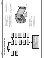


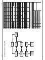
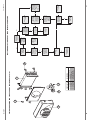


![Fountain Program [ 001930 ]](http://vs1.manualzilla.com/store/data/006022682_1-35065e157ee046f990de9548b34d6090-150x150.png)