1
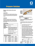
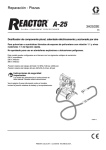
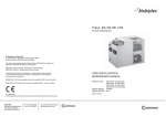
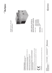
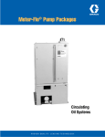
Single Line Parallel
Lubrication System
Multiple Point Lubrication Using Oil or Grease
L12100
LubriSystem
of reservoirs allow a system to be designed precisely for your
application. Reservoirs include a fill stud fp reservoir refilling.
Automated Centralized Lubrication System that can be used in
virtually any application where centralized operation is desired.
Timer
•
•
•
•
•
•
•
•
•
Dependable
Economical
Versatile
Adjustable injector outputs
Up to 100 or more lube points
Use with oil or grease
Wide range of options
Modular design
Option of aluminum or stainless steel injectors and manifolds
INTRODUCTION
LubriSystem™ utilized one of three (3) types of pumps: a singlestroke air-operated pump; a multiple-stroke hand-operated
pumpr; or a continuous flow, electric motor pump. Fed from a
lubrican reservoir mounted above, the pump output is delivered
to oil or grease metering valves (called meters or injectors) which
distribute lubricant to bearing points. Oil or grease (NLGI #1 or
lighter) may be used with the hand-operated and air-operated
pump. Oil or NLGI #00 or ligher grease may be used with the
electic motor pump. Air-operated pumps require a solenoidoperated air valve and controller to activate the pump. Electic
motor pumps use an electric motor (115 VAC is standard) and
a solid-state timer device to activate the pump. The injectors
are mounted in manifolds supplied by Graco. The bearing point
injectors mount at the bearing point and require no manifold.
Various accessories are available to simplify installation. An
optional pressure switch or gauge may be added at the pump
outlet port if required.
LubriSystem is referred to as a single-line, parallel system. This
means that when the solid-state timer, controller or operator
activates the pump, llubricant is forced down a single main
line to manifolds, and from there through parallel lines from
individual injectors to the lube points. If bearing point injectors
are used, no manifolds are required. Instead, the single main line
branches into parallel lines feeding the bearing point injectors. In
both cases the injectores inject lubricant to a bearing shown in
Figure 1. Once lubricant is dispensed at the lube points, system
pressure is vented by the pump. This allows the injectors to prime
themselves in preparation for the next lubrication cycle.
Solid-state timer can be set to control the solenoid or motor to
initiate lube cycle at intervals of 1/2 minute to 32 hours.
Manifolds and Injectors
One manifold can distribute lubricant to as many as eight (8)
injectors. Injectors come in six (6) sizes to meet a range of lube
requirements. Bearing point injectors are fed directly from the
pump through parallel branch lines and require no manifold.
Tubing, Hardware, Fittings and Accessories
LubriSystem utilezes tough 3/16 in and 5/16 in heavywall nylon
tubing and brass fittings for lube points. Mounting hardware and
accessories such as reservoir low-level switches and injector
indicator assemblies are available.
FEATURES AND BENEFITS
A more efficient method of applying lubricant, resulting in less
machine downtime, increased productivity, and a safer work
environment. In addition to these benefits, LubriSystem also
provides:
•
•
•
•
•
•
•
•
SYSTEM COMPONENTS
•
•
Pumps
Positive displacement, air-operated pumps are available in two
(2) pressure ratios. A manually-operated pump and an electric
motor pump are also offered. Several different types and sizes
Page 1
Stainless steel injectors and manifolds available for corrosive
environments
Easy system design and modification
Inexpensive components and installation
Fast payback! In terms of savings in lube maintenance manhours alone, LubriSystem usually pays for itself within the
first year
Easy adjustability to meet a wide range of operating
conditions
Quick-connect fill stud on pump permits complete refill in
minutes
High-pressure pump can serve more points with longer
tubing runs
Pump construction internally relieves system pressure,
requiring no extra cost in external valving
Several reservoir sizes available to fit a variety of
applications
Visual indicator pin available fo system diagnostics
L12100
HAND-OPERATED
PUMP
SEE PAGES
9 THROUGH 12
BEARING
AIR-OPERATED
PUMP
SEE PAGES
4 THROUGH 8
INJECTOR
MANIFOLD
SOLENOIDOPERATED
AIR VALVE
BEARING
POINT
INJECTOR
ELECTRIC
MOTOR
PUMP
SEE PAGES
13 THROUGH 160
BEARING
FEED LINES
Figure 1. LubriSystem Diagram
Page 2
L12100
SYSTEM OPERATION
As shown in Figure 1, when the electic motor or solenoid-operated air valve receives a signal from the timer, or when the operator actuates
the handle, the pump is activated. The pump dispenses lubricant either into the mainline tubing which distributes the lubricant to the
manifolds, feeding each injector, or to lines supplying bearing point injectors. Each of the injectors is sized to measure and dispense the
proper amount of lubricant based on the size of the bearing. Details of the operation of each component are included in this brochure.
INTERCHANGEABLILITY
LubriSystem components are functionally interchangeable with other commonly used single-line, parallel injector systems. Air inlet and
lube outlet ports are 1/4-8 NPT, typical of most other pumps in the field. Injectors have a 3/16 in tube connection as standard. An accossory
indicator/adaptor allows 1/8 in tubing to be connected to the outlet. Mounting dimensions of LubriSystem components are very close to
theose of other systems. And, if some components, there is a direct interchangeability in form and fit as well as function.
APPLICATIONS
Typical applications of LubriSystem include the following:
•
Mobile Equipment
•
- Palletizers
- Stackers
- Front End Loaders
- Haul Trucks
- Blast Hole Drill Rigs
- Paving Equipment
•
Plastic/Rubber Industrial Equipments
- Tire Presses
- Injection Molders
•
Food Processing Equipment
- Peelers
- Washers
- Mixers
- Ovens
- Conveyors
- Can-making Machines
Page 3
Packaging Equipment
- Wrappers
•
Lumber Equipment
- Debarkers
- Edgers
- Slasher Decks
- Planers
- Stoker Grates
- Saw Guides
- Winders
- Presses
L12100
AIR-OPERATED PUMPS
DESCRIPTION
LubriSystem air-operated pumps (Figure 2) are available in two
lube-to-air power ratios to meet your system requirements. The
standard pump has a 9:1 ratio while the high-pressure pump
provides a 24:1 ratio. Output per stroke is 1.5 cubic inches (24.59
cm³) for standard pumps and 1.4 cubic inches (22.95 cm³) for
high-pressure pumps. Both pump bodies are made from strong,
lightweight aluminum and are furnished with a corrosion-resistant
coating. This coating provides a tough, durable, impact-resistant
finish which is exceptionally resistant to corrosion; excellent
for salt spray or humid environments. Pump piston and cylinder
bore are precision machined and finished to minimize wear and
discourage corrosion.
Reservoirs in several different sizes are available in transparent
plastic. All reservoirs mount directly to the pump and are easily
interchangeable. The level of lubricant in the reservoir is easily
checked due to the transparent plastic.
Figure 2. Air-Operated Pump
SYSTEM SIZING AND CALCULATIONS
* To check that a system is not oversized for a pump, the following
calculations need to be performed:
1.
Sum the output volume of all injectors used in the system.
2. Add the number of injectors used in the system and multiply by .004 cu.
in. This is total volume required to re-prime the injector.
3. Total system requirement is the sum of 1 and 2, and should be less than
50% of the total output per cycle for the pump selected. (The 50% is a
rule of thumb to allow for line expansion and fluid compressibility.)
If totals are more than 50% of pump output, the following steps can be taken:
1. Select smaller injectors and increase system cycle frequency.
2. Split the system up and use 2 or possibly more pumps.
Page 4
L12100
All reservoirs used with grease are equipped with a spring-loaded
follower which provides a positive, air-free supply of grease to the
pump. Pumps are equipped with a fill stud and strainer to allow
easy filling of the reservoir from a supply source. Oil reservoirs
are also equipped with a fill cup and strainer, allowing easy
refilling from an oil can. Optional low-level switches, timers and
solenoid-operated air valves are available to custom design your
application.
The solenoid-operated air valve, designed for use with airoperated pumps, is controlled by a solid-state timer or other
electronic controller. The solenoid is a 115 VAC, three-way,
normally-closed valve with a manual override. The manual
override simplifies system testing, line filling, and line bleeding
by allowing the operator to control when the pump dispenses
lubricant. When the solenoid receives a 115 VAC signal from its
controller, it actuates the valve to allow air flow to the pump. While
the solenoid is energized, the pump strokes forward sending
lubricant through the system. When the solenoid is de-energized,
the pump piston returns. An FR unit (FRL with high pressure
pumps) must be used upstream of the air valve to remove harmful
dirt and water from the air supply. Air pressure should be a
maximum of 100 psi (7 bar) for the high-pressure pump or 150
psi (10 bar) for standard pumps.
MOUNTING
Sturdy bracket, with four mounting holes, holds pump with
solenoid and reservoir. Assembly should be mounted in a
protected, centralized, and readily accessible location. Pump must
be mounted in a vertical position only, with reservoir up. Use four
5/16 inch or M8 machine screws at the mounting holes to ensure
secure placement.
FEATURES / BENEFITS
Proven dependable performance. Many pumps now in use have
logged over 5 years of trouble-free operation. Pump features
include:
•
Simple design—few moving parts results in less wear and
downtime.
•
Compact modular construction allows you to customize the
pump/reservoir design to fit your application.
•
Lube supply status at a glance.
•
Rugged aluminum construction to provide lightweight features
with heavy-duty capabilities.
Page 5
OPERATION
Figure 3 portrays the air-operated pumps in the “at-rest” position.
The figure represents both standard and high-pressure pumps.
The description of operation applies to both. At this point, air is
not present and spring (8) pressure has moved piston (7) to the
down position. When the piston is down, flapper valve (1) opens
and lubricant from reservoir fills lube chamber (9) above the
piston. Spring pressure on check valve (4) prevents lubricant from
flowing through the outlet port. This condition also allows residual
pressure in the lube lines to raise ball (3), pass through screen (2)
and return to the reservoir. This venting of the output lines allows
injectors to prime themselves.
When air at 40 to 100 psi (3 to 7 bar) is applied to air inlet port
(6), pressurized air fills air chamber cavity (12), forcing piston
(7) upward, pressurizing lubricant in lube chamber (9). The
pressurized lubricant closes flapper valve (1) (preventing the
discharge lubricant from being fed back to the reservoir) and
forces check valve (4) open, allowing lubricant to flow through
lube outlet port (5) to the injectors. When air pressure is removed,
spring (8) returns piston (7) to the down position to repeat the
cycle. On the standard pump a diaphragm (10) is used to seal
the air chamber cavity (12), on the high-pressure pump, this is
accomplished by a lip seal (11).
OPTIONS
Low-Level Switches
Several assemblies are available to provide a signal when the
lubricant level is low. Low-level switch assemblies used on oil
reservoirs depend on floats that fall with the depletion of lubricant
and actuate contacts on the switch. Switch assemblies used
on grease reservoirs are actuated when a cable attached to the
grease follower is pulled away from the switch as the follower
reaches the low position. Limit switch assemblies used on grease
reservoirs are rated at 15 amps. Oil reservoirs use 10-watt reedtype switches.
The low-level assemblies with a 15 amp rating are often used
to activate a warning device such as light or alarm. The 10-watt
assemblies are used to provide input to controllers which may be
programmed to use the input signal as desired.
Solid-State Timer
This solid-state timer can be used to initiate pump cycles
on a time basis at intervals from 1/2 minute to 32 hours. A
built-in memory retains the cycle time for 1-1/2 hours during
power failure or machine shutdown to resume from the point
where it was suspended. For details, see Literature No. 14521.
Sophisticated multi-function controllers are also available for use
in systems using pressure switches. Refer to literature No. 14540
(LC-1000) and 14750 (WMP III).
L12100
1
2
RESERVOIR
1
2
RESERVOIR
3
3
9
9
4
5
4
8
5
7
8
12
10
7
11
6
STANDARD
12
1. FLAPPER VALVE
2. SCREEN
3. BALL
4. CHECK VALVE
5. LUBE OUTLET PORT
6. AIR INLET OUTLET PORT
6
HIGH-PRESSURE
7. PISTON
8. SPRING
9. LUBE CHAMBER
10. DIAPHRAGM
11. LIP SEAL
12. AIR CHAMBER CAVITY
Figure 3. Air-Operated Pump Operation
SPECIFICATION
125 VDC
0.5 amp
Pumps:
250 VDC
0.25 amp
Air Inlet Pressure
Type
Single-pole, double-throw
Stadard
40 to 150 psi (3 to 10 bar)
Oid Reservoir Only - 10 Watt
High-Pressure
40 to 100 psi (3 to 7 bar)
115 VAC
10 Watt
Type
Single-pole, single-throw reed
type switch, normally-open or
normally closed
Lube Outlet Pressure
Standard (9:1)
360 to 1350 psi (25 to 93 bar)
High-Pressure (24:1)
960 to 2400 psi (66 to 165 bar)
Pump Output per Stroke
Solid-State Timer:
Electrical
115 VAC, 50/60 Hz, 3 amp (max)
1.4 cu.in. (22.95 cm3)
Temperature range - Operating
Storage
0ºF to 131ºF (-18ºC to 55ºC)
-67ºF to 185ºF (-55ºc to 85ºC)
Air Inlet Port
1/4-18 NPSF
Enclosure
High Impact Plastic
Lube Outlet Port
1-4/18 NPSF
Component Technology
Solid-State CMOS
Operating Temperatures (w/NLGI #1)
40ºF to 135ºF (4ºC to 50ºC)
Cycle Frequency, Adjustable
Lubricant
Oil or Grease (NLGI #1 or lighter)
Range 1
1/2 min to 30 mins
Type
Air-actuated positive
displacement
Range 2
1/2 hour to 32 hours
“On” Time
0.2 min to 13 mins
Standard; LED Indicator, Manual Run
Buttom; Vibrations
5g’s, 50 Hz
Standard
1.5 cu.in. (24.59 cm3)
High-Pressure
Low-Level Switches:
Grease or Oil Reservoir 15 amp
Switch
115 VAC
15 amp
Page 6
L12100
DIMENSIONS
Figure 4 presents layouts of the standard and high-pressure pumps along with common options.
NOTE
DIMENSIONS SHOWN ARE IN INCHES
(MILLIMETERS)
STANDARD 9:1 PUMP
OPTIONS
0.75 (19.05)
1.00
(25.4)
2.85
(72.9)
3.75
(96.3)
3.25
(82.6)
“A”
PLASTIC GREASE
RESERVOIR
15 AMP GREASE LOWLEVEL
1.75
(44.5)
3.03
(76.9)
0.50
(12.7)
3.563
(90.50)
6.87 DIA.
(175)
1/2-14 NPSM
COND. CONN.
4.56
(116)
5.063
(129)
3.69
(93.7)
0.343 DIA.
(8.71)
MNTG. HOLES
TYP.
15 AMP OIL
LOW-LEVEL
RESERVOIR SIZE
6
12
20
A DIMENSION
12.72 (323)
17.22 (437)
24.22 (615)
HIGH-PRESSURE 24:1 PUMP
ALL DIMENSIONS ARE
IDENTICAL TO 9:1
PUMPS
EXCEPT THOSE
SHOWN.
5.38
(137)
1/2-14 NPSM
COND. CONN.
1/2-14 NPSF
COND. CONN.
2.62
(66.68)
10 WATT OIL
LOW-LEVEL
1.50
(38.1)
3.0
(76.2)
2.19
(55.6)
0.875 HEX
(22.23)
1/2 COND.
CONN.
MANUAL OVERRIDE
1/4 NPSF
SOLENOID
VALVE
Figure 4. Air-Operated Pumps - Dimensions
Page 7
L12100
SYSTEM ORDERING INFORMATION
COMPONENT ORDERING INFORMATION
LUBRISYSTEM AIR-OPERATED PUMPS
Description
Part No.
LUBRISYSTEM AIR-OPERATED PUMPS COMPONENTS
Old Part No.
Standard - Oil
563574
550-000-170
Standard Pump (no reservoir)
12 pint (5.68 liter) plastic reservoir
563575
550-000-180
High-Pressure Pump (no reservoir)
20 pint (9.46 liter) plastic reservoir
563576
550-000-190
6 pint (2.84 liter) plastic reservoir w/10 watt
low-level switch
Plastic Reservoirs
(for oil only, standard or high-pressure)
563577
550-000-230
20 pint (9.46 liter) plastic reservoir w/10 watt
low-level switch
563578
550-000-240
–
550-000-250
6 lb (2.72 kg) plastic reservoir
563571
550-000-050
12 lb (5.44 kg) plastic reservoir
–
550-000-060
20 lb (9.06 kg) plastic reservoir
–
550-000-070
6 lb (2.72 kg) plastic reservoir w/ low-level
switch
563572
550-000-080
12 lb (5.44 kg) plastic reservoir w/low-level
switch
563573
Standard - Grease*
20 lb (9.06 kg) plastic reservoir w/low-level
switch
Part No.
Old Part No.
563579
550-000-280
–
550-000-790
Pumps
6 pint (2.84 liter) plastic reservoir
12 pint (5.68 liter) plastic resevoir w/10 watt
low-level switch
550-000-090
–
550-000-100
6 pint (2.84 liter) plastic reservoir
–
550-000-940
12 pint (5.68 liter) plastic reservoir
Dis
550-000-950
High-Pressure - Oil
20 pint (9.46 liter) plastic reservoir
–
550-000-960
6 pint (2.84 liter) plastic reservoir w/10 watt
low-level switch
–
550-001-000
12 pint (5.68 liter) plastic resevoir w/10 watt
low-level switch
–
550-001-010
20 pint (9.46 liter) plastic reservoir w/10 watt
low-level switch
–
550-001-020
High-Pressure - Grease*
*
Description
6 pint (2.84 liter)
–
185-100-820
12 pint (5.68 liter)
562892
185-100-380
20 pint (9.46 liter)
562893
185-100-390
6 lb (2.72 kg)
562907
185-100-780
12 lb (5.44 kg)
562896
185-100-540
20 lb (9.06 kg)
562897
185-100-550
6 pint (2.84 liter) size
563014
456-010-171
12 pint (5.68 liter) size
563015
456-010-172
20 pint (9.46 liter) size
563016
456-010-173
6 pint (2.84 liter) size
563318
521-001-050
12 pint (5.68 liter) size
563316
521-001-030
20 pint (9.46 liter) size
563317
521-001-040
Plastic Reservoir
(for grease*, standard or high-pressure)
10 Watt Low-Level Switch
(for oil, plastic reservoir only)
15 Amp Low-Level Switch
(for oil, plastic reservoir only)
15 Amp Low-Level Switch
(grease applications)
All Grease Reservoirs
563322
521-001-110
115 VAC Solenoid Valve
563315
521-001-020
24 VDC Solenoid Valve
563332
521-002-100
DC Timer
557925
550-200-040
Solid State Timer, 115 VAC
562872
163-400-000
6 lb (2.72 kg) plastic reservoir
–
550-000-820
Reservoir Strap
557878
550-050-240
12 lb (5.44 kg) plastic reservoir
–
550-000-830
Tie Rod Clamp (3 required)
557046
461-301-030
20 lb (9.06 kg) plastic reservoir
–
550-000-840
6 lb (2.72 kg) plastic reservoir w/ low-level
switch
550-400-792
550-000-850
Standard Pump Repair/Rebuild Kit
(includes Pump Diaphragm)
563762
–
High Pressure Pump Repair Kit
563772
550-402-500
12 lb (5.44 kg) plastic reservoir w/low-level
switch
–
550-000-860
20 lb (9.06 kg) plastic reservoir w/low-level
switch
–
550-000-870
See page 25 for Fill Studs and Couplers
Nominal grease reservoir size is based on a direct conversion of oil reservoir capacity and does not reflect volume loss due to the follower and spring.
Actual volumes contained are: 6 lb (2.6 lb), 12 lb (5.8 lb), 20 lb (11.8 lb).
Page 8
L12100
HAND-OPERATED PUMPS
DESCRIPTION
The multiple stroke, positive-displacement LubriSystem Hand
Pump (Figure 5) delivers 0.125 cubic inches (2.0 cm3) with each
stroke of the handle. The LubriSystem Hand Pump is available
with standard clear plastic reservoirs for either oil or grease.
Modular pump/reservoir design plus built-in features readily tailor
the LubriSystem Hand Pump to a wide range of applications.
The pump is sturdily built of aluminum and steel in a compact,
space-saving package. Even with an integrally mounted 20-pint or
20-pound capacity reservoir, it stands only 25.3 inches (644 mm)
high, is 7.25 inches (184 mm) wide and 11.03 inches (280 mm)
deep. It requires only 24.3 inches (617 mm) clearance from the
mounting surface for a full handle pull.
MOUNTING
Sturdy bracket, with two mounting holes, hold pump with
reservoir. The assembly components should be mounted in a
protected, centralized and readily accessible location. Pump must
be mounted in a vertical position only, with reservoir up. Use two
3/8 in or M10 machine screws at the mounting holes to ensure
secure placement.
Figure 5. Hand-Operated Pump
Page 9
L12100
FEATURES / BENEFITS
•
Interchangeable reservoirs make it easy to customize the
pump package for each application.
•
Simple, positive-displacement pump design keeps the number
of wear parts to a minimum for extended pump life.
•
Built-in bleed mechanism provides system pressure venting
when the pump handle is returned to the fully upright
position.
•
3000 psi pressure gauge provides a fast check on system
status.
7
6
1
VIEW “A-A”
FRONT
VIEW
10
9
OPERATION
Figure 6 shows a cutaway view of a hand-operated pump. As the
pump handle (1) is pulled down, piston (2) moves forward past the
detent (3) closing the relief to tank port (4). Further forward motion
of piston (2) displaces the volume of lubricant in cavity (8) through
connecting port (5) and check valve (6) and to the outlet (7). The
handle is then partially returned until the detent ball (3) contacts,
but does not retract into, the ball indent cavity. If the handle is
returned too far, the pressure built up in the lube cavity (8) will be
vented, indicated by a decrease in the pressure gauge’s reading.
Continue to stroke the pump until the pressure gauge reads 1500
psi (103 bar) for oil or 2500 psi (173 bar) for grease). After system
pressure has been attained, causing all the injectors to dispense
lubricant, the pump handle is returned to the full upright position
(past the detent). This allows system pressure to vent through port
(4) back to reservoir, thereby allowing the injectors to reset and
prime for their next delivery of lubricant.
PRESSURE GAUGES
Pressure Gauges are installed in the pump outlet to allow the
operator to know when correct pressure has been attained.
When correct pressure has been reached, the operator returns
the handle to the full upright position, venting line pressure and
allowing the injectors to reset.
A 8
1.
2.
3.
4.
HANDLE
PISTON
DETENT BALL
RELIEF-TO-TANK
PORT
5. CONNECTING PORT
6. CHECK VALVE
7. OUTLET
8. LUBE CAVITY
9. BALL DETENT CAVITY
10. GAUGE PORT
A
2 3
4
5
Figure 6. Hand-Operated Pump - Operation
(Full upright position shown)
SPECIFICATION
Pump Body Material
Aluminum and steel
Pump Output
0.125 cu.in (2.0 cm3) per stroke
Max Operating Pressure
3000 psi (207 bar)
Force to Operate Handle
20 lbs (9 kg) per 1000 psi (69 bar)
Lubricant
Oil or Grease (NLGI #1 or lighter)
Reservoir Capacities
(for oil or grease, plastic)
6 pints (2.84 liters) or 6 lbs (2.72 kg)*
12 pints (5.68 liters) or 12 lbs (5.44 kg)*
20 pints (9.46 liters) or 20 lbs (9.06 kg)*
*Nominal grease reservoir size is based on a direct conversion of oil
reservoir capacity and does not reflect volume loss due to the follower
and spring. Actual volumes containd are: 6 lb (2.6 lb), 12 lb (5.8 lb), 20
lb (11.8 lb).
Page 10
L12100
DIMENSIONS
Figure 7 provides dimensions for the hand-operated pump.
DETENT POSITION
PRESSURE RELIEF POSITION (FULLY UPRIGHT)
17.03 FULL STROKE (433)
3.91
(99.3)
FILL CUP OIL
RES’V ONLY
11.0 PUMPING (279) 0.75
(19.05)
STROKE
3.25
(82.6)
FILL STUD GREASE
RES’V ONLY
1.00
(25.4)
15.00
(381)
PUMPING
RANGE
1.28
(32.52)
“A”
2.37
(60.2)
1/4 NPT
LUBE OUTLET
11.09
(282)
0-3000 PSI PRESSURE GAUGE
RESERVOIR SIZE
6
12
20
A DIMENSION
10.5 (267)
15 (381)
22 (559)
Figure 7. Hand-Operated Pump - Dimensions
Page 11
0.437 (11.10)
DIA. MOUNTING HOLES,
TWO PLACES
2.37
(60.2)
6.0
(152.4)
21.25
(53.98)
7.25
(184)
L12100
SYSTEM ORDERING INFORMATION
LUBRISYSTEM HAND-OPERATED PUMPS
Description
Part No.
Old Part No.
6 pint (2.84 liter) w/3000 psi gauge
–
550-000-430
12 pint (5.68 liter) w/3000 psi gauge
564419
550-000-440
20 pint (9.46 liter) w/3000 psi gauge
564420
550-000-450
6 lb (2.72 kg) w/3000 psi gauge
564421
550-000-460
12 lb (5.44 kg) w/3000 psi gauge
564422
550-000-470
20 lb (9.06 kg) w/3000 psi gauge
564423
550-000-480
Hand-Operated Pump w/Plastic Reservoir for oil
Hand-Operated Pump w/Plastic Reservoir for grease*
COMPONENT ORDERING INFORMATION
LUBRISYSTEM HAND-OPERATED PUMP COMPONENTS
Description
Part No.
Old Part No.
Pump Assembly
563580
550-000-520
3000 psi Gauge
557864
543-362-000
6 pint (2.84 liter)
562904
185-100-750
12 pint (5.68 liter)
562889
185-100-060
20 pint (9.46 liter)
562890
185-100-070
*6 lb (2.72 kg)
562905
185-100-760
*12 lb (5.44 kg)
562884
185-100-000
*20 lb (9.06 kg)
562885
185-100-010
Reservoirs
Plastic, used for oil:
Plastic, used for grease:
See page 25 for fill studs and couplers
* Nominal grease reservoir size is based on a direct conversion of oil reservoir capacity and does not reflect volume loss due to the follower and spring. Actual volumes
contained are: 6 lb (2.6 lb), 12 lb (5.8 lb), 20 lb (11.8 lb).
Page 12
L12100
ELECTRIC MOTOR PUMPS
FEATURES / BENEFITS
DESCRIPTION
PUMP FEATURES INCLUDE:
The electric motor LubriSystem pump (Figure 8) is a rugged,
reliable pump for applications using oil or fluid grease as the
lubricant. The motor itself is a high torque, gear-reduction motor
operating at 300 rpm and 115 VAC 50/60 Hz. (Other voltages are
available.) The motor drives a positive displacement, self-priming
gear pump capable of pumping at a rate of 2.0 cubic inches (32.8
cm3) per minute at 1,000 psi (69 bar). All electric motor pumps are
equipped with a Hirshman Connector. A 20 foot mating cable is
available as an accessory (see ordering information on page 16).
No motor starter or capacitor is required. Pumps may be ordered
with an integral solid-state timer or control may be provided by an
external system controller.
•
Reliable gear pump design proven in mobile equipment
applications.
•
Energy efficient motor uses only 25 watts.
•
Allows the design of an all-electric system; no air required.
Reservoirs in several different sizes are available in transparent
plastic. All reservoirs mount directly to the pump and are easily
interchangeable. The level of oil in the reservoir is easily checked
due to the transparent plastic. Pumps are equipped with a fill stud
and filter screen to allow easy filling of the reservoir from a supply
source. Optional low-level switches and timers are available to
custom design your application.
MOUNTING
Sturdy bracket, with four mounting holes, holds pump with
motor, timer and reservoir. The assembled components should
be mounted in a protected, centralized and readily accessible
location. Pump must be mounted in a vertical position only, with
reservoir up. Use four 5/16 inch or M8 machine screws at the
mounting holes to ensure secure placement.
OPERATION
Figure 9 portrays the pump in the “at rest” position. When the
motor (1) is energized, the gear pump (2) runs, drawing in
lubricant through inlet (3). Pressure builds in passage (4) moving
the poppet (5) to the right, sealing off the retainer (6) opening
to the tank. As the pump continues to run, pressure exceeds
the check valve (7) resistance. The check valve opens allowing
lubricant to flow through internal porting to the lube outlet and
injector distribution system. After 1250 psi (86 bar) is obtained,
the relief valve (8) vents excess flow back to the tank maintaining
constant pressure.
When the motor is de-energized, pressure relieves through the
orifice (9) and the check valve closes. The accumulator effect of
the system now pushes on the poppet until the force exceeds the
relieving force in passage (4). At this time the poppet moves to
the left, allowing lubricant pressure to vent to the tank through an
opening in the retainer passage. This allows the injectors in the
system to reset and prepare for the next cycle.
3
9
4
2
8
6
5
7
1
1.
2.
3.
4.
5.
Figure 8. Electric Motor LubriSystem Pump
Page 13
MOTOR
GEAR PUMP
INLET
PASSAGE
POPPET
6.
7.
8.
9.
RETAINER
CHECK VALVE
RELIEF VALVE
ORIFICE
Figure 9. Electric Motor Pump Operation
L12100
DIMENSIONS
OPTIONS
Figure 10 provides dimensions for the electric motor pump.
Solid-State Timer
If the pump is equipped with the optional solid-state timer. The “on
time” and “cycle time” are controlled via screwdriver adjustable pots. A
manual run button is integral with the pump to be used for system check
and system filling/purging. When depressed it will activate the pump
output as long as button is held in. Pressing button will not reset timer.
The timer option fits neatly beneath the motor cover, adding nothing to
the overall dimensions of the pump package.
Low-Level Switches
Several assemblies are available to provide a signal when the reservoir
oil level is low. Low-level switch assemblies depend on floats that fall
with the depletion of lubricant and actuate contacts on the switch.
These switches are rated at 10 watts and are used to activate a warning
device such as a light or alarm. The 10-watt assemblies are used to
provide input to controllers which may be programmed to use the input
signal as desired.
“C”
3.75
(95.25)
SPECIFICATION
Pumps:
Lube Outlet Pressure (max)
1000 psi (69 bar)
Pump Output
2.0 in3 (33cm3 per min)
Lube Output Port
1/4-18 NPSF
Lubricant
Oil (all temperatures), NLGI #00 grease for 50ºF or higher,
NLGI #000 grease for below 50ºF
Type
Electric-motor driven, postive displacement, self-priming
4.56
(115.9)
0.343 DIA.
(8.71) MOUNTING HOLES
(TYP.)
1.75
(44.45)
5.062
(128.5)
Low-Level Switches:
10 watt switch: Rating at
115 VAC
10 Watt
Type
Single-pole, single-throw reed type switch, normally-closed
Electical Specifications:
12 VDC w/w/o timer
Applied Voltage
12 VDC
Current Draw
5 amps
Duty Cycle
30% (run time not to exceed 2 min)
24 VDC w/w/o timer
Applied Voltage
24 VDC
Current Draw
5 amps
Duty Cycle
30% (run time not to exceed 2 min)
115 VAC w/w/o timer
Appllied Voltage
115 + 10% VAC, 50/60 Hz
Current Draw
0.2 amps
Duty Cycle
30% (run time not to exceed 2 min)
230 VAC w timer
5.75 (146) DIA.
RESERVOIR SIZE
C DIMENSION
Applied Voltage
230 + 10% VAC, 50/60 Hz
6 PINT (2.84 LITERS)
16.28 (413.5)
Current Draw
0.1 amps
12 PINT (5.68 LITERS)
20.78 (527.8)
Duty Cycle
30% (run time not to exceed 2 min)
20 PINT (9.46 LITERS)
27.78 (705.6)
Timer:
On Time Range
30-90 sec
Off Time Range
10-45 min
Figure 10. Electric Motor Pump - Dimensions
Page 14
L12100
WIRING DIAGRAMS FOR ELECTRIC PUMPS
WHITE
HIRSCHMANN
CONNECT OR
BLACK
BLACK
RE D + IGNITIO N
GREEN
RE D + IGNITIO N
GREEN GROUND
12 VA C
GREEN
WHITE + BATTE RY
WHITE + BATTER Y
GROUND TO 8-32 SCRE W
ON TRANSFORME R
BLACK
GROUND TO 8-32 SCRE W
ON MOUNTIN G BRACKET
+
VD C
-
USE TIM E D ELAY F USE
115 VAC - 0.25A
230 VA C - 0.125A
FUSE BOTH BATTER Y + (WHITE)
AND IGNITIO N ( RED) :
12 VD C - 10A
24 VD C - 5A
RE D
YELLO W
+
~
~
CAP
+
-
BLACK
BLACK - BATTER Y
BLUE
HIRSCHMANN
CONNECT OR
+
-
12 VDC
MANUA L
RUN
MANUAL
RUN
DC
MOTOR
12 VDC
MOTOR
For 12 & 24 VDC with Timer
HIRSCHMANN
CONNECT OR
For 115 & 230 VAC with Timer
BLACK
WHITE
GREEN GROUND
HIRSCHMANN
CONNECTOR
GREEN
GROUND TO 8-32 SCRE W
ON MOUNTIN G BRACKET
115 VAC
BLACK
GREEN
GROUND TO 8-32 SCREW
ON TRANSFORMER
FUSE BATTER Y + (WHITE):
12 VD C - 10A
24 VD C - 5A
USE TIME DELAY FUSE
115 VAC - 0.25A
12 VAC
+
~
+CAP
+ 12 VDC
12 VDC
MOTOR
DC
MOTOR
For 12 & 24 VDC without Timer
Page 15
For 115 VAC without Timer
~
BLACK
WHITE +
WHITE +
BLUE
BLACK -
L12100
PUMP ORDERING INFORMATION
EGP -
XX
–
XX
–
XXX
–
XX
VOLTAGE OPTION
V1 - 12 VDC (W/TIMER)
V2 - 24 VDC (W/TIMER)
V3 - 115 VAC (W/TIMER)
V4 - 230 VAC (W/TIMER)
V5 - 12 VDC (W/O TIMER)
V6 - 24 VDC (W/O TIMER)
V7 - 115 VAC (W/O TIMR)
SERVICE OPTION
OS - OIL SERVICE
GS - GREASE SERVICE
RESERVOIR OPTION
R03 - 6 PINT PLASTIC OIL/LIQUID GREASE
R04 - 12 PINT PLASTIC OIL/LIQUID GREASE
R05 - 20 PINT PLASTIC OIL/LIQUID GREASE
*LOW LEVEL OPTION
LL-LOW LEVEL SWITCH (10 WATT)
*FOR OIL SERVICE ONLY, OMIT IF NOT REQUIRED
REPLACEMENT PARTS ORDERING INFORMATION
ORDERING INFORMATION
Description
Description
Part No.
Pump Assembly w/Timer (no reservoir),
12 VDC, Oil
Pump Assembly w/Timer (no reservoir),
12 VDC, Grease
Pump Assembly w/Timer (no reservoir),
24 VDC, Oil
Pump Assembly w/Timer (no reservoir),
24 VDC, Grease
Pump Assembly w/Timer (no reservoir),
115 VAC, Oil
Old Part No.
Consult Factory
–
550-001-685
Consult Factory
563588
550-001-695S
Consult Factory
Part No.
Old Part No.
Reservoir Assemblies, 6 pt, Plastic
–
550-050-960
Reservoir Assemblies, 12 pt, Plastic
–
550-050-970
Reservoir Assemblies, 20 pt, Plastic
–
550-050-980
Replacement Gear Pump
557822
540-800-603
Replacement Motor, 12 VDC, 115/230 VAC
557284
493-040-034
Replacement Motor, 24 VDC
557288
493-040-071
Replacement Transformer, 115 VAC
563135
492-210-009
Replacement Transformer, 230 VAC
–
492-210-008
Replacement Capacitor/Rectifier, 115/230 VAC
563136
492-240-098
Timer, 12 VDC, 115/230 VAC
557210
492-110-014
Pump Assembly w/Timer (no reservoir),
115 VAC, Grease
Consult Factory
Pump Assembly w/Timer (no reservoir),
230 VAC, Oil
Tmer, 24 VDC
557211
492-110-015
Consult Factory
563142
492-240-244
Pump Assembly w/Timer (no reservoir),
230 VAC, Grease
20ft Cable w/Mating Connector, 12/24 VDC w/
Timer (4 Condictor)
Consult Factory
563140
492-240-196
Pump Assembly w/out Timer (no
reservoir), 12 VDC, Oil
20ft Cable w/Mating Connector, 12/24 VDC
w/o Timer, 115/230 VAC (all) (3 Conductor)
Consult Factory
Pump Assembly w/out Timer (no
reservoir), 12 VDC, Grease
Consult Factory
Pump Assembly w/out Timer (no
reservoir), 24 VDC, Oil
Consult Factory
Pump Assembly w/out Timer (no
reservoir), 24 VDC, Grease
Consult Factoru
Pump Assembly w/out Timer (no
reservoir), 115 VAC, Oil
Pump Assembly w/out Timer (no
reservoir), 115 VAC, Grease
564426
550-001-831
Consult Factory
Page 16
L12100
INJECTORS AND MANIFOLDS
DESCRIPTION
Oil injectors in two types and grease injectors in one type (Figure
11) are available for use in the lubrication system. The first, a
manifold injector, is designed specifically for mounting in the
LubriSystem manifold. The second, a bearing point injector, is
designed to be mounted at the lubrication point and does not
require a manifold.
Both injector styles are designed with a unique feature, allowing
output capacity to be changed using adjustment spacers. This
reduces the number of replacement injectors to be stocked. It
also permits increasing/decreasing an injector’s lube delivery
capacity, in order to deal with unexpected needs to change the
amount of lubricant delivered to lube points after installation.
Manifold injectors are available for oil or grease and are positivedisplacement, spring-loaded devices used in the LubriSystem
manifold. These injectors are available in six displacements,
from 0.0015 to 0.024 cu.in. (0.025 to 0.039 cm3) of lubricant per
injector cycle. The choice of displacements fits a wide range of
applications.
Positive-displacement injectors dispense a precisely metered
amount of oil or grease to a lube point with every lube cycle.
Injectors are inexpensive and disposable. They should be
replaced if not functioning properly. If an injector is to be
disassembled for purposes of adding or deleting output
adjustment spacers, great care must be taken to make sure
both the inside and outside of the injectors are dirt-free when
reassembled in the system.
Input to the injector is from the manifold. Output is into lines
delivering the lubricant to a specific lube point. Injectors are
available in either an aluminum alloy or stainless steel. The
inlet port of all injectors utilizes a 1/2-24 in tubing. An indicator
adaptor is available to change 3/16 in tube connection to 1/8
in for use with 1/8 in tubing. Stainless steel injectors come
standard with 1/8 in fittings.
Bearing point injectors are positive-displacement, spring-loaded
devices that can be mounted directly at the lubrication point.
An injector cycle indicator is available for use in system
diagnostics. This cycle indicator can be attached to the output
end of aluminum injectors. When the pump cycles, and the
indicator is pressurized, the stem of the indicator extends. When
the indicator is not pressurized the indicator stem is not visible.
These indicators give an immediate visual indication that the
injector has cycled. Injector cycle indicators are not available for
stainless steel or bearing point injectors.
Manifolds are available in two types of materials: aluminum and
stainless steel. The number and configuration of outlet ports
can also be ordered to meet the specific needs of the system.
Refer to pages 21, 22 and 23 for more specific information on
dimensions and configurations of manifolds.
Aluminum manifolds are available with 4 outlet ports in an
in-line, single-sided configuration. They are also available with
8 outlet ports in an in-line, double-sided configuration. These
manifolds are dimensionally interchangeable with many of those
used on other single-line parallel injector systems.
Stainless steel manifolds are available with 1, 2, 3, or 4 outlet
ports in an in-line configuration. These also interchange with
others in common use.
Figure 11. Injectors and Manifolds
Bearing point injectors are available in five output capacities,
from 0.0015 to 0.012 cubic inches (0.025 to 0.2 cm3) of
lubricant per injector cycle.
Input to the bearing point injector is from the pump, using a
parallel branch from the main line. Bearing point injectors utilize
a stainless steel body. The inlet port of this type of injector is
1/8-27 NPSF. The outlet port is a standard 1/8-27 NPTF male
thread for attachment at the lubrication point.
Page 17
Plugs are available to close off any port not required. A torque
of only 1 to 2 ft-lbs is required to provide a leak tight connection
between the injectors and manifold.
L12100
INJECTOR OPERATION
Note: Although oil and grease injectors operate in the same
manner, each design has been optimized for use with its type
of lubricant and system operating conditions. Oil injectors are
designed for lower viscosity lubricants, higher cycle rates and
lower operating pressure. They will not function properly with
grease. Grease injectors are designed for grease consistency
lubricants, low cycle rates and higher operating pressure. Their
output accuracy will decrease with lighter lubricants and their life
will be considerable reduced if used on high cycle rate systems.
Lubricant from the pump is supplied either to the manifold which,
in turn, provides lubricant to the manifold injectors, or directly
to the bearing point injector. Figure 12 represents a typical
manifold injector. When pressurized lubricant enters the injector
inlet, piston A shifts until the valve port is exposed. Lubricant
flows through the valve port and is directed behind piston B to
chamber B1. This forces piston B towards the outlet, dispensing a
measured amount of lubricant from chamber B2 to the bearing.
When the pump has completed its dispense cycle it allows the
pressure in the feed lines to vent. This allows piston A to shift
back towards the inlet, opening the valve port to piston B. Piston
B shifts, transferring the volume of lubricant in chamber B1
to chamber B2. This primes the injector in preparation for the
next dispense cycle. This operation is identical in both types of
injectors.
VALVE
PORT
PISTON B
PISTON A
FLOW
CHAMBER B2
CHAMBER B1
Figure 12. Injector Operation
Page 18
L12100
INJECTOR CYCLE INDICATOR OPERATION
The injector cycle indicators are attached to the output side of
aluminum injectors installed in an in-line manifold only. During
the lube cycle, they provide a visual indication that the injector
has cycled. Figure 13 represents an injector cycle indicator. As the
pump pressurizes the injector, the injector piston moves toward
the outlet, pushing a measured amount of lubricant toward the
lubrication point. This piston contacts the plunger of the indicator
moving it in the same direction. As the plunger moves toward the
indicator outlet, the indicator stem is pushed toward the end of
the indicator. This opens the outlet of the indicator releasing the
lubricant and extends the indicator stem past the indicator body.
This gives an indication that the injector has cycled.
When the pump has completed its cycle, and the injector piston
has retracted, the spring-loaded indicator stem retracts, leaving
the end of the stem flush with the indicator body and sealing the
outlet port of the indicator.
DIRECTION
OF LUBRICANT
FLOW
INDICATOR STEM
PLUNGER
DIRECTION OF
PISTON MOVEMENT
INDICATOR
(SHOWN EXTENDED)
INJECTOR
PISTON
Figure 13. Injector Cycle Indicator
Part No: 563769 (550-401-261)
The outlet of the injector cycle indicator accepts 1/8 inch tubing.
DIMENSIONS
SPECIFICATION
Manifold:
Operating Pressure (max)
INJECTOR INDICATOR OUTLET
(1/8 TUBE)
2500 psi (173 bar)
Injectors:
Operating Pressure (max)
2500 psi (173 bar)
Min Pressure to Fire Injectors
450 psi (31 bar)
Vent Pressure
160 psi max (11 bar)
Min On-Time
30 sec
Min Off-Time
3 min
Injectors
All manifold injectors are approximately 2.125 inches (54 mm)
long with a 0.625 inch (15.88 mm) hex body. For injectors utilizing
from one to four output adjustment spacers add 0.04 inch (1 mm)
per spacer to the length.
Installing Injector into
Manifold
2-3 ft lbs
All bearing point injectors are approximately 2.5 inches (63.5 mm)
long with a 0.625 (15.88 mm) hex body. For injectors utilizing from
one to four output adjustment spacers add 0.04 inch (1 mm) per
spacer to the length. Figure 14 provides dimensions for the two
types of injectors.
Tightening Tube Nut
18-36 in lbs
Manifolds
Torque Specs:
Figures 15 and 16 provide dimensions for aluminum and stainless
steel manifolds.
Page 19
L12100
STAINLESS STEEL MANIFOLD INJECTOR
(OIL)
ALUMINUM MANIFOLD INJECTOR
(OIL OR GREASE)
2.125
(53.97)
0.38 (9.65)
HEX
2.125
(53.97)
0.38 (9.65)
HEX
FOR 3/16 TUBE
FOR 1/8 TUBE
INJECTOR CYCLE INDICATOR (BRASS)
FOR ALUMINUM INJECTOR
BEARING POINT INJECTOR (OIL)
PLATED CARBON
STEEL
STAINLESS
STEEL
1/8 TUBE
INJECTOR
0.969 (24.61)
2.55 (64.77)
1.156 (29.36)
1/8-27 NPSF
1/8-27 NPTF
Figure 14. Injector and Indicator Dimensions
Injectors can be identified by the following characteristics:
HIGH OUTPUT
INJECTOR BODY
SLEEVE
“O” RING
“O” RING
1/2-24 THD. INLET5/8 HEX
HEAD
METER VALVE
ASSEMBLY
OUTPUT
SPACER
WASHER
CUP
“O” RING
NUT
OUTPUT
END
METER BODY
SPRING
5/8 HEX
Page 20
L12100
DOUBLE-SIDED
SINGLE-SIDED
0.875
(22.23)
0.875 (22.23)
0.812
(20.62)
TYP.
0.375 (9.53)
0.812
(20.62)
0.375 (9.53)
TYPICAL
SIDE VIEW
B
0.664 (16.87)
B
TYP.
.266 DIA. MTG. HOLES (6.76)
1/4-18 NPSF SUPPLY PORTS
D
D
0.375 (9.53)
0.375 (9.53)
C
C
0.203 (5.16)
0.203 (5.16)
1.000 (25.4)
1/2 - 24 (TYP)
1.000 (25.4)
SINGLE-SIDED DIMENSION
DOUBLE-SIDED DIMENSION
HOLE QTY
B DIM
C DIM
D DIM
HOLE QTY
B DIM
C DIM
D DIM
8
0.906
(23.01)
3.500
(88.90)
4.250
(108.0)
4
0.906
(23.01)
3.500
(88.90)
4.250
(108.0)
Part No: 561122 (550-401-783)
Part N0: 561120 (550-401-774)
Figure 15. Extruded Aluminum Manifold Dimensions and Configurations
Page 21
0.375
(9.53)
L12100
1/4-20 X 1 1/2
1/2 HEX HEAD SCREW
(2 SUPPLIED)
0.812
(20.6)
(TYP.)
0.75
(19.05)
0.75
(19.05)
S
M
L
0.664
(16.87) 1.00
(25.4)
1/4-18 NPSF
BOTH ENDS
STAINLESS STEEL
NO. OF PORTS
S
M
L
PART NO.
OLD PART NO.
1
0.625
(15.8)
1.25
(31.7)
1.75
(44.5)
563764
550-401-101
2
0.594
(15.1)
2.0
(50.8)
2.5
(63.5)
563765
550-401-102
3
0.563
(14.3)
2.75
(69.8)
3.25
(82.6)
563766
550-401-103
4
0.532
(13.5)
3.5
(88.9)
4.0
(101.6)
563767
550-401-104
Figure 16. Stainless Steel Manifold Dimensions and Configurations
Page 22
L12100
ORDERING INFORMATION
LUBRISYSTEM MANIFOLD AND ACCESSORIES
INJECTOR ACCESSORIES
Description
Description
Part No.
Old Part No.
Manifolds - Stainless Steel
Inlet Adaptor, 1/2-27 in FM x 1/8 in NPSF Female
Part No.
Old Part No.
Dis
550-401-820
1 Port Manifold
563764
550-401-101
Outlet Adaptor, 3/8-24 in FM x 1/8 NPT Female
–
550-402-020
2 Port Manifold
563765
550-401-102
Injector Outlet Plug
557901
550-150-130
3 Port Manifold
563766
550-401-103
Aluminum Ouput Adjustment Spacer
557898
550-150-020
4 Port Manifold
563767
550-401-104
Stainless Steel Ouput Adjustment Spacer
557905
550-150-180
Injector Cycle Indicator
563769
550-401-261
Manifolds - Aluminum
4 Port Manifold
561120
550-401-774
8 Port Manifold Double Sided
561122
550-401-783
Aluminum Manifold
15M038
550-350-040
Stainless Steel Manifold
561115
550-401-120
Aluminum Manifold
555808
550-050-210
Stainless Steel Manifold
556425
412-700-394
Manifold Accessories
Manifold Injector Port Plugs
End of Line Manifold Plugs
Aluminum Alloy Injectors (Oil)
Aluminum Alloy Injectors
(Grease)
Stainless Steel Injectors (Oil)
Bearing Point Injectors (Oil)
Size #
Output
cu.in. (cm3)
Adjustment
Spacers
Part No.
Old Part No.
Part No.
Old Part No.
Part No.
Old Part No.
Part No.
Old Part No.
0
.002 (0.033)
–
563628
550-100-001
563627
550-100-000
–
550-100-110
–
550-100-480
1
.005 (0.082)
1
563630
550-100-011
563629
550-100-010
–
550-100-120
–
550-100-490
2
.009 (0.148)
2
563632
550-100-021
563631
550-100-020
–
550-100-130
–
550-100-500
3
.012 (0.197)
3
563634
550-100-031
563633
550-100-030
–
550-100-140
–
550-100-510
4
.020 (0.328)
4
563636
550-100-041
563635
550-100-040
563639
550-100-150
–
550-100-520
8
.026 (0.426)
4
563638
550-100-081
563637
550-100-080
–
–
–
–
556587
423-700-052
556586
423-700-051
556587
423-700-052
–
–
Spart O-Ring
Page 23
L12100
ACCESSORIES/HARDWARE
Figure 17. Tubing (unplasticized nylon)
Figure 18. Union
HEAVYWALL LUBE LINES (TUBING)
Description
Part No.
TEES AND UNIONS
Old Part No.
Main Line (pump to manifold):
5/16 in OD x .059 wall (7.9 x 1.5), black,
60 ft (18.3 m)
561132
550-450-230
Burst Pressure Min - 1500 psi (103 bar)
at 75ºF (24ºC)
Description
Part No.
Old Part No.
Male Branch Tee, 5/16 tube, 1/8 NPTF Brass
556636
435-410-040
Union Tee, 5/16 tube, Brass
556637
435-420-030
Union, 3/16 tube, Brass
556647
435-470-020
Union, 5/16 tube, Brass
556648
435-470-040
Point Distribution Line (injector to lube
point):
3/16 in OD x .044 wall (4.8 x 1.1), black,
60 ft (18.3 m)
561131
550-450-190
Burst Pressure Min - 2000 psi (138 bar )
at 75ºF (24ºC)
Figure 19. Connectors
SELF-ALIGNING FERRULES AND NUTS
BRASS CONNECTORS
Description
Part No.
Old Part No.
Description
Part No.
Old Part No.
Brass Nut, w/captive ferrule, 3/16 tube
556660
435-702-340
Female Connector, 3/16 tube x 1/8 NPTF
556642
435-450-020
Brass Nut, w/captive ferrule, 5/16 tube
556666
435-702-503
Female Connector, 5/16 tube x 1/8 NPTF
556643
435-450-050
Stainless Steel Nut, 1/8 tube
556651
435-500-150
Male Connector, 3/16 tube x 1/8 NPTF
556644
435-460-030
Stainless Steel Ferrule, 1/8 tube
556654
435-510-050
Male Connector, 5/16 tube x 1/8 NPTF
556645
435-460-060
Brass Inserts for 5/16 tubing (pack of 20)
557963
550-402-330
Male Connector, 5/16 tube x 1/4 NPTF
556646
435-460-070
Page 24
L12100
Figure 20. Tubing Straps
Figure 22. Harness Clamps
TUBING STRAPS
HARNESS CLAMPS AND BRACKETS
Description
Part No.
Old Part No.
Description
Part No.
Old Part No.
100 pieces, 11.5 in (292 mm)
563770
550-402-340
5/16 (7.94) diameter
557943
550-400-040
3/8 (9.53) diameter
557946
550-400-070
7/16 (11.11) diameter
557944
550-400-050
1/2 (12.7) diameter
557947
550-400-080
5/8 (15.22) diameter
557945
550-400-060
Description
Part No.
Old Part No.
Air Line Restrictor, 1/2 x 1/8, M to F Pipe
561113
550-400-010
Air Line Restrictor, 3/8 x 1/8, M to F Pipe
561114
550-400-460
Pressure Gauge Kit, 3000 psi for Air Pump
–
560-001-780
Fill Studs, Pneumatic Oil Pumps
563155
506-189-010
Figure 21. Elbows
MISCELLANEOUS
ELBOWS
Description
Part No.
Old Part No.
Steel Pipe and Adaptor Elbows
1/4-28 (male) x 1/8 NPTF (female), 90º
Adapter Elbow
15K740
550-400-800
90º Street Elbow, 1/8 NPTF
15K783
509-110-000
Pneumatic & Hand Grease Pumps
557374
506-189-001
45º Street Elbow, 1/8 NPTF
557395
509-111-000
Electric Oil & Fluid Grease Pumps
557880
550-050-300
3/16 tube x 1/8 NPTF
556638
435-440-030
Pneumatic Oil Pump
558906
506-322-000
5/16 tube x 1/8 NPTF
556639
435-440-060
Pneumatic & Hand Grease Pumps
558906
506-322-000
5/16 tube x 1/4 NPTF
556640
435-440-070
Electric Oil & Fluid Grease Pumps
557877
550-050-230
Fill Couplers, mate w/above fill studs
Brass Male Tube Elbows
Page 25
HOW-TO-ORDER LUBRISYSTEM
ANALZING SYSTEM REQUIREMENTS
FOR MORE INFORMATION
1.
Determine individual bearing requirements. Graco
literature No. L20115 provides a procedure for
calculating the lubricant volume requirement for
individual lube points.
Literature No. L20102 - LubriSystem Design Guide. Guidelines
and information for LubriSystem component selection and
design calculation charts.
2.
Analyze bearing locatoins and group those that can
conveniently fed from a single manifold. See ordering
instructions.
Literature No. L14530 - TC-1000 Timer/Counter
Analyze routine maintenance setup to determine
reservoir options and other accessories required.
Literature No. L14750 - WMP III Maxi-Monitor †
3.
ORDERING INSTRUCTIONS
Literature No. L14521 - Solid-State Timer
Literature No. L14540 - LC-1000 Controller †
Literature No. L14760 - Multi Purpose Controller †
Literature No. L15521 - Pressure Switch
4.
Select the quantity of each injector size required.
5.
Specify the manifolds required based on the groupings of
injectors.
Literature No. L20115 - Procedure for calculating the
lubricant volume requirement for various types of rotating and
moving lubrication points.
6.
*Order a Timer or Controller.
† Requires a system mounted pressure switch.
7.
Select pump/reservoir configuration and specify part
number using one of the following:
•
Grease Reservoir - specify appropriate assembly
number.
•
Oil Reservoir - specify appropriate assembly
number.
8.
*Order Part No. 553315 (521-001-020), 115 VAC or
553332 (521-002-100), 24 VDC solenoid valve. (Install in
pump air inlet port.)
9.
Specify appropriate pressure switch, in one is
required, using Bulletin No. L15521. Part No. 557828
(542-210-107) is usually used.
10. Specify Part No. 557559 (514-215-001) if a pressure
gauge is required (0-3000 psir). See Bulletin No. L15326.
11. Select fittings, accessories and mounting harware to
complete installation.
*Required only for air operated pumps.
All written and visual data contained in this document are based on the latest product information available at the time of publication. Graco reserves the right to make changes at any time without notice.
Contact us today!
To receive product information or talk with a Graco representative,
call 800-533-9655 or visit us online at www.graco.com.
©2012 Graco Inc. Form No. L12100 Rev. C 8/12 Printed in U.S.A. All other brand names or marks are used for identification purposes and are trademarks of their respective owners. All written and visual
data contained in this document are based on the latest product information available at the time of publication. Graco reserves the right to make changes at any time without notice.