1
Detailed Drive Operation 2-111
Speed Feedback Loss Ride Through Configuration
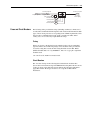
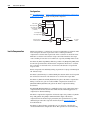
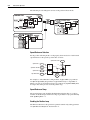
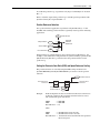
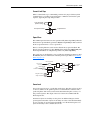
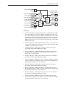
Parameter 151 [Logic Command] bit 2, "TackLoss Rst" provides a manual switch
between primary and alternate speed feedback devices with a “0” to “1” bit
transition. A transition from “1” to “0” does not cause a change in operation.
Parameter 152 [Applied LogicCmd] bit 2, "TachLoss Rst" shows the status of
parameter 151 [Logic Command] bit 2 "TachLoss Rst" switch.
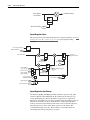
Setting parameter 153 [Control Options], bit 16 "Auto Tach Sw" to a value of “1”
enables the automatic switching of speed feedback devices when a failure is
detected. A value of “0” disables the automatic switching of speed feedback
devices. Only automatic switching from the primary device specified in parameter
222 [Mtr Fdbk Sel Pri] to the alternate device specific in parameter 223 [Mtr Fdbk
Sel Alt] is available. Switching from the alternate to the primary device must be
done manually by setting parameter 151 [Logic Command], bit 2 "TackLoss Rst"
from “0” to “1”.
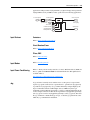
Parameter 155 [Logic Status] bit 12, "Tach Loss Sw," shows which speed feedback
device is currently active. A value of “0” in bit 12 indicates that the primary speed
feedback device selected in [Mtr Fdbk Sel Pri] is active. A value of “1” in bit 12
indicates that the alternate speed feedback device selected in [Mtr Fdbk Sel Alt] is
active.
Parameter 222 [Mtr Fdbk Sel Pri] selects the primary speed feedback device. It is
not intended to use the sensorless selection as the primary (or active) speed
feedback device as there is no feedback loss detection used with sensorless
operation.
Parameter 223 [Mtr Fdbk Sel Alt] selects the alternate speed feedback device. Any
selection of feedback devices, including sensorless operation is available providing
a corresponding motor type and associated feedback device is present.
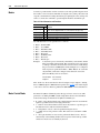
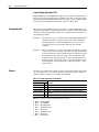
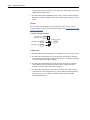
Settings for parameter 222 [Mtr Fdbk Sel Pri] and parameter 223 [Mtr Fdbk Sel
Alt]:
0=
1=
2=
Encoder 0
Encoder 1
Sensorless
3 = Reserved
4 = Motor Sim
5 = FB Opt Port0
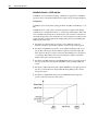
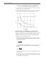
Parameter 224 [TachSwitch Level] sets the detection level for the automatic speed
loss switch over routine. A drop in feedback speed at the percent of rated speed
over a 0.5 mSec interval will cause a tach switch from primary to alternate device.
Setting this level lower will make the speed detection more sensitive and lower the
minimum speed at which a speed switch could occur. Setting this level higher will
make the speed switch less sensitive and raise the minimum speed for speed switch
detection.
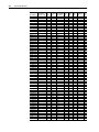
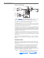
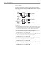
Parameter 320 [Exception Event1] bits 2 through 5 show the error status of the
corresponding speed feedback device.
2=
3=
4=
5=
Encdr0 Loss
Encdr1 Loss
FB Opt0 Loss
FB Opt1 Loss
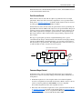
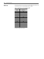
Parameter 365 [Fdbk LsCnfg Pri] and parameter 366 [Fdbk LsCnfg Alt] set the
feedback loss configuration for each feedback device. The primary feedback device
should be configured to 1 "Alarm". The alternate feedback device should typically
be configured to 2 "FltCoastStop".