1
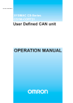
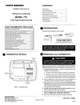
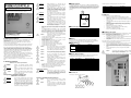
WARNING
Wiring, maintenance, or inspection must be
performed after turning OFF the power supply,
confirming that the CHARGE indicator (or status
indicators) is OFF, and after waiting for the time
specified on the Inverter front cover. Not doing so
may result in electrical shock.
WARNING
Do not damage, pull on, apply stress to, place
heavy objects on, or pinch the cables. Doing so
may result in electrical shock, operation stoppage,
or burning.
INSTRUCTION SHEET
Thank you for purchasing an OMRON product. Read this thoroughly and
familiarize yourself with the functions and characteristics of the product
before using it. Keep this instruction sheet for future reference.
WARNING
Do not attempt to disassemble or repair the Unit.
Doing either of these may result in electrical
shock, injury, or damage to the product.
WARNING
Provide safety measures in external circuits, i.e.,
not in the 3G3MV-PCORT21-E, in order to ensure
safety in the system if an abnormality occurs due
to malfunction of the Unit or another external
factor affecting the Unit operation. Not doing so
may result in serious accidents.
•
•
Emergency stop circuits, interlock circuits, limit circuits, and
similar safety measures must be provided in external control
circuits.
The 3G3MV-PCORT21-E will attempt to send a stop command
to the V7AZ when it detects any unrecoverable error. However,
there is no guarantee that the 3G3MV-PCORT21-E will
successfully stop the motor. As a result of this, external safety
measures must be provided to ensure safety in the system.
Caution
© 2005 OMRON Europe B.V.
Control Business Unit. All rights reserved.
1643495-1C
■ General Precautions
Observe the following precautions when using the VARISPEED Inverters and
peripheral devices.
This Instruction Sheet does not contain illustrations of the product with
protective covers removed from the V7AZ. Make sure that these protective
covers are on the inverter before use.
The user must operate the product according to the performance specifications
described in this instruction sheet and in the operation manual of the inverter.
•
•
•
•
•
•
•
•
Before using the product under conditions which are not described in the
inverter manual or applying the product to nuclear control systems, railroad
systems, aviation systems, vehicles, combustion systems, medical equipment,
amusement machines, safety equipment, and other systems, machines, and
equipment that may have a serious influence on lives and property if used
improperly, consult your OMRON representative.
Make sure that the ratings and performance characteristics of the product are
sufficient for the systems, machines, and equipment, and be sure to provide the
systems, machines, and equipment with double safety mechanisms.
Make sure that these safety precautions and the individual product manual
accompany the product and are delivered to the final user.
Locations subject to direct sunlight.
Locations subject to temperatures or humidity outside the range
specified in the specifications.
Locations subject to condensation as the result of severe
changes in temperature.
Locations subject to corrosive or flammable gases.
Locations subject to exposure to combustibles.
Locations subject to dust (especially iron dust) or salts.
Locations subject to exposure to water, oil, or chemicals.
Locations subject to shock or vibration.
Caution
Do not allow foreign objects to enter inside the
product. Doing so may result in fire or malfunction.
Caution
Do not apply any strong impact. Doing so may
result in damage to the product or malfunction.
Caution
Be sure to wire correctly and securely. Not doing
so may result in injury or damage to the product.
Caution
Be sure to firmly tighten the screws on the
terminal block. Not doing so may result in fire,
injury, or damage to the product.
Caution
Keep these safety precautions in a convenient location even after reading
them.
Caution
■ Safety Precautions
Definition of Precautionary Information
DANGER
Indicates an imminently hazardous situation
which, if not avoided, will result in death or serious
injury.
WARNING
Indicates a potentially hazardous situation which,
if not avoided, could result in death or serious
injury.
Caution
Indicates a potentially hazardous situation which,
if not avoided, may result in minor or moderate
injury, or property damage.
•
•
•
•
Do not store, install, or operate the product in the
following places. Doing so may result in electrical
shock, fire or damage to the product.
Carefully handle the product because it uses
semiconductor elements. Careless handling may
result in malfunction.
Take appropriate and sufficient countermeasures
when installing systems in the following locations.
Not doing so may result in equipment damage.
Locations subject to static electricity or other forms of noise.
Locations subject to strong electromagnetic fields and magnetic
fields.
Locations subject to possible exposure to radioactivity.
Locations close to power supplies.
Setting Precautions
DANGER
Install devices to stop operation as required to
ensure safety. Equipment damage may result.
This is particularly important when operation is set
to continue for communications errors because
the Inverter will continue operation.
Transportation, Installation, Wiring, and
Maintenance Precautions
WARNING
WARNING
Do not touch the conductive parts such as internal
PCBs or terminal blocks while power is being
supplied. Doing so may result in electrical shock.
Turn ON the input power supply only after
mounting the front cover, terminal covers, bottom
cover, Operator, and optional items. Leave them
mounted in place while power is being supplied.
Not doing so may result in electrical shock,
malfunction, or damage to the product
Operation and Adjustment Precautions
Caution
Do not carelessly change Inverter's settings.
Doing so may result in injury or damage to the
product.
Caution
Be sure to perform the setting switch settings
correctly and confirm the settings before starting
operation. Not doing so may result in malfunction
or damage to the product.
Unit Description
The 3G3MV-PCORT21-E can be attached to an OMRON YASKAWA MOTION
CONTROL V7AZ Inverter to control the inverter via a CANopen network as shown
in the picture. Its purpose is to control the speed and the reference of the inverter.
The application side in the CANopen network is responsible for correct behaviour
of the application. In that sense, the 3G3MV-PCORT21-E is just a transparent
gateway.
This table shows the meaning of the pins on the CAN connector.
Pin
1
2
3
4
5
Name
CAN_VCAN_L
CAN_H
CAN_V+
Description
Ground/ 0V
CAN_L bus line (dominant low)
No connection
CAN_H bus line (dominant high)
External power supply
■ CANopen
3G3MV-PCORT21-E
Memobus
3G3MV-PCORT21-E
Wiring, maintenance, or inspection must be
performed by authorized personnel. Not doing so
may result in electrical shock or fire.
CAN bus
WARNING
Model
3G3MV
Inverter
General Specifications
Item
Ambient operating temperature
Ambient operating humidity
Storage temperature
Dimensions
Weight
CAN power supply
CAN current consumption
Specifications
-10°C to 55°C
10% to 90% (with no condensation)
-20 to +75°C
73mm x 53mm
36g
24V typical (18V to 30V)
42mA maximum
Wiring
Connect the cable of the CANopen network to the connector of the 3G3MVPCORT21-E. The maximum length of the cable depends of the selected bit rate.
For the advised way of wiring, see section on Installation Procedure.
LED Indicators
Indicator
RUN
(green)
ERR
(red)
Status
OFF
Flashing
ON
OFF
Flashing
ON
Meaning
Unit is not powered.
CANopen is pre-operational.
CANopen is operational.
Unit has no error.
Unit has a recoverable error.
Unit has an unrecoverable error.
Rotary Switch Settings
The bit rate of the CANopen network must be set before the unit is powered on.
Changing rotary switch settings after power-on will have no effect.
Position
Bit rate [kbit/s]
Maximum wiring length
[m]
0
10
5000
1
20
2500
2
50
1000
3
125
500
4
250
250
5
500
100
6
800
62
7
1000
10
1)
1)
8
1)
1)
9
1)
Positions 8 and 9 cause the unit to halt at power-up and turn on the ERR LED.
To recover, correct the switch setting and power the system off and on.
Connectors
The unit uses a 5-pin open style connector.
The CANopen interface has the following features:
•
It uses the memobus interface to read/write data in the V7AZ.
•
The CANopen Application layer and communication profile is of version
V4.01
•
Node number is equal to the memobus node number (n153). Possible
values are 1..32.
•
The mapping between CANopen objects and memobus registers is
transparent.
•
Mailbox functionality is realized to directly send a read or a write
memobus command for registers that are not mapped to CANopen
objects by default.
•
Both producer and consumer of heartbeats.
•
Storage of settings and mappings in non-volatile memory.
•
Output TPDO’s upon SYNC message,
Process received RPDO’s upon SYNC message.
Installation Procedure
Power-on the V7AZ Inverter with the Digital Operator unit attached to the Inverter.
Make the following selections via Digital Operator:
1.
Change Run Command Selection parameter (n003) to use the
RS422/485 communications reference (value 2).
2.
Change Frequency Reference Selection parameter (n004) to use the
RS422/485 communications reference (value 6).
3.
Change the memobus node number (n153) to the desired CANopen
node number.
Power-down the Inverter and follow the maintenance precautions given in this
sheet. Before powering on, take the following steps:
•
Remove the Digital Operator and the terminal cover from the Inverter.
•
Attach the 3G3MV-PCORT21-E and attach the terminal cover.
•
Secure the 3G3MV-PCORT21-E with the screw of the terminal cover.
•
Attach the cable of the CANopen network as indicated by the picture
below.
•
Select the CANopen bit rate via the rotary switch of the 3G3MVPCORT21-E.
Caution
The CANopen cable should be conducted straight
up. The purpose of placing the cable in this
direction is to prevent EMC problems.
The following picture shows a side-view of the inverter and the CANopen cable:
■ CANopen States
■ Using SYNC Function
At power-up the 3G3MV-PCORT21-E will be in pre-operational state. Entering
stopped state and entering pre-operational state is the same. When either of these
states is entered, the failsafe data is written if the 3G3MV-PORT21-E is configured
to do so.
Applying failsafe data means zeroes are written into object 2101.01 which will
result in stopping the motor if it was running.
Whether or not the 3G3MV-PCORT21-E should use failsafe data in such cases is
defined by object 2100.01.
TPDO’s can be configured to be output upon request, i.e. upon reception of a
SYNC frame or on a defined number of SYNC frames.
RPDO’s can be configured to be received but to process its contents later, i.e.
upon reception of a SYNC frame or on a defined number of SYNC frames.
Entering any CANopen state can be done by sending the right CANopen NMT
command to do so. Entering pre-operational state will also occur upon the
following error situations:
•
Heartbeat Consumer Error.
•
Entering Error Passive Mode
•
Bus Off Error or CAN Power Fail Occurred
When too many reception or transmission failures occur the 3G3MV-PCORT21-E
may come in error passive state or even in bus off state. These errors are
recoverable. This means that the 3G3MV-PCORT21-E will attempt to recover from
these states automatically.
To do so take the following steps per PDO:
•
Disable the PDO by setting the most-significant bit in the COB-ID
•
Change the transmission type to the number of SYNC messages
•
Enable the PDO by clearing the most-significant bit in the COB-ID
The transmission type object may contain the number of SYNC messages to
receive first before the 3G3MV-PCORT21-E will actually send out the TPDO or
process the contents of the RPDO.
Note: It is advised to keep the rate of SYNC messages as low as possible to keep
the busload low. A high SYNC rate is not useful for reading out objects from the
3G3MV-PCORT21-E. The internal refresh rate of the V7AZ is not high enough to
make a SYNC message cycle time lower than 200ms useful.
■ PDO Mapping
■ Product Specific CANopen Objects
All CANopen objects are in the appropriate .eds file that can be downloaded from
http://technicalsupport.europe.omron.com.
Mapping of Input Objects, index 2001 (read only):
Subindex
Type
Meaning
Memobus register
1
16 bit
Inverter status
0020h
2
16 bit
Actual speed
0024h
3
16 bit
Motor current
0027h
Mapping of Output Objects, index 2101:
SubIndex
Type
Meaning
Memobus register
1
16 bit
Inverter control
0001h
2
16 bit
Speed reference
0002h
If the contents of either Output Object is incorrect, the inverter will set the Data
Setting Error Flag in its status register. This may cause that the 3G3MVPCORT21-E sends out a PDO with this object but only in operational state and
only if the object is mapped.
The error flag will be reset immediately when the inverter receives only correct
data in the entire memobus cycle.
Failsafe Setting, index 2100:
Subindex
Type
Meaning
1
8 bit
Failsafe setting
Mailbox Command Objects, index 2110:
Subindex
Type
Meaning
1
8 bit
Handshake
2
8 bit
Function code
3
4
16 bit
16 bit
Memobus register
Memobus data
Explanation
If zero, the 3G3MVPCORT21-E will stop the
motor upon entering preoperational by clearing
object 2101.01 If not zero,
the 3G3MV-PCORT21-E will
not change the contents of
object 2101.01
Explanation
The command is send on a
rising edge of bit 0 in this field.
On a falling edge, the
handshake bit in the response
handshake field is cleared.
03 : Read one register
10 : Write one register
See V7AZ manual
Put data here in case of a
write function.
Mailbox Response Objects, index 2010 (read-only):
Subindex
Type
Meaning
Explanation
1
8 bit
Handshake
Bit 0 in this field is set when
the response is received.
It is cleared on a falling edge
of handshake bit in the
command handshake field.
2
8 bit
Function code
03 : Read one register
10 : Write one register
3
16 bit
Memobus register
See V7AZ manual
4
16 bit
Memobus data
In case of a read function the
read data is put here.
4
8 bit
Memobus endNormally zero. When the
code
V7AZ returns a memobus
error the end-code is stored in
this field.
For other details on objects, e.g. default values and min/max values, these are
defined in the .eds file.
By default the following PDO mapping exists:
PDO
COB-ID
Mapped Objects by default
RPDO0
200 + node ID
2101.01
RPDO1
300 + node ID
2101.02
RPDO2
400 + node ID
2110.01 .. 2110.04
TPDO0
180 + node ID
2001.01
TPDO1
280 + node ID
2001.02
TPDO2
380 + node ID
2001.03
TPDO3
480 + node ID
2010.01 .. 2010.05
Note: RPDO2 and TPDO3 are CANopen PDO messages that contain more than
one object. All objects are placed in string to build the PDO. All other PDO’s
consist of only one object.
The mapping of objects into PDO’s can be modified. However, not all objects can
be mapped. Product specific input objects can be mapped to TPDO’s. Product
specific output objects can be mapped to both RPDO’s and TPDO’s. This allows
confirmation of proper reception of the inverter command/reference.
If required, RPDO mappings may contain so-called dummy objects of size 8, 16 or
32 bit. It allows the use of existing PDO’s on the CAN bus but using only a part of
the data in those PDO’s. The PDO data bytes mapped as ‘dummy’ will be ignored.
The following dummy objects are available:
•
8 bit: object 5.00
•
16 bit: object 6.00
•
32 bit: object 7.00
In order to change the PDO mapping, take the following steps:
•
Disable the PDO by setting the most-significant bit in the COB-ID (e.g.
object 1400.01)
•
Set the number of entries (e.g. object 1600.00) to zero.
•
Map an object to the PDO (e.g. object 1600.01). The mapping data has
the following format:
Least significant word
Most significant word
MSB
LSB
Object number
Sub-index
Size (bits)
•
Add as much objects as required to the PDO (max. 8 objects).
•
Set the number of entries to the number of objects mapped.
•
Enable the PDO by clearing the most-significant bit in the COB-ID
When the 3G3MV-PCORT21-E receives too short PDO messages (i.e. less data
bytes than configured in the mapping) the PDO is discarded and the appropriate
EMCY message is send out.
When the 3G3MV-PCORT21-E receives a PDO message that is longer than the
data configured in the mapping, the mapped part of the PDO is used and the
remaining bytes will be ignored. No EMCY message will be sent.
■ Details on Mailbox
Before sending a new memobus command, make sure that the handshake flags
are both cleared (objects 2010.01 and 2110.01). Once the command is defined the
command handshake flag may be set. Only the read and write commands are
supported. If a read command is requested the data field in the command mailbox
is ignored. If any other command is requested the 3G3MV-PCORT21 will set endcode 1. In all other cases, the end-code object will contain the end-code defined by
the V7AZ inverter.
When the inverter has processed the command it will send a response to the
3G3MV-PCORT21 and the input mailbox objects will be filled accordingly: the
response handshake flag will be set (object 2010.01). Always check the end-code
is zero.
When the mailbox functionality is to be used regularly, it is advised to map the
output objects that change often in one RPDO. Also it is advised to map the
handshake object into a separate RPDO in such a case.
A similar advice applies to the input mailbox (containing the memobus response):
only map the required objects that change often, e.g. in many applications only
handshake, data and end-code need to be mapped.
■ Mailbox Example
Assuming that the inverter node number is 1, and assuming that the default PDO
mappings are used, the following PDO sequence is an example of writing (10h)
data (first: 0002h, later: FFFFh) into a memobus register (011Fh):
PCORT21
COB-ID
LEN
Data
Meaning
Receive
401
6
00 10 011F 0002
preparation
Receive
401
6
01 10 011F 0002
trigger command
Transmit
481
7
01 10 011F 0002 00
response
Receive
401
6
00 10 011F 0002
preparation
Transmit
481
7
00 10 011F 0002 00
prepared
Receive
401
6
00 10 011F FFFF
Incorrect data
Receive
401
6
01 10 011F FFFF
trigger command
Transmit
481
7
00 10 011F FFFF 21
Error response
Note: For more details on the memobus registers, data and error codes, see the
inverter manual.
■ EMCY Messages
Format of EMCY messages
Byte
Contents
0
LSB EMCY Code
1
MSB EMCY Code
2
ER (current errors)
3
Communication / Protocol Errors
4
Device Errors
5
EMCY trigger
6
Reserved
7
Reserved
List of defined EMCY messages (byte 0 and 1)
EMCY
Meaning
code
0000
No Error / Error resolved
8110
CAN overrun. Receive or transmit queue overflow
8120
CAN in error passive mode
8130
Heartbeat Error
8140
Recovered from bus off
8210
PDO length Error (too few data bytes)
FF00
Device Specific.
Contents of ER (current errors, byte 2)
Bit
Meaning
0
Generic Error
1
Not used
2
Not used
3
Not used
4
Communication Error
5
Not used
6
Not used
7
Device Error
Contents of Communication/Protocol Errors (byte 3)
Bit
Meaning
0
Receive queue overflow (CAN overrun)
The Unit was not able to process all the messages that it was
configured to receive due to a too high bus load.
This bit is negated as soon as the receive queue did not
overflow again during 100 ms.
1
Transmit queue overflow
The Unit was not able to transmit all CAN frames between 2
inverter access cycles. This bit is negated as soon as the
Unit is able to transmit all data again.
2
CAN in Error Passive Mode
The communication interface of the Unit has detected a high
occurrence of errors on the bus.
This bit is negated when the bus communication is resumed
without errors i.e. when enough correct frames have been
send/received.
3
Recovered from Bus Off
The Unit has recovered from the Bus Off state
This bit is negated at the next EMCY message or at least
within 100 ms after the bus off recovery.
And / or
Recovered from CAN Network Power Error
The Unit has recovered from the CAN Network Power Error
This bit is negated at the next EMCY message or at least
within 100 ms after the CAN Network Power recovery.
4
PDO Length Error
The received RPDO contains less data bytes than
configured. As a result, the RPDO is ignored.
This bit is negated when a PDO is received with the correct
amount of data bytes
5..6
Not used
7
Heartbeat error
This bit is negated again when two valid heartbeat messages
are received.
Contents of ER Device Errors (byte 4)
Bit
Meaning
0
Inverter error / Memobus communication error.
1
Parameter storage error
The Unit was not able to store / restore parameters to / from
non-volatile memory.
This bit is negated again when another attempt is done to
store / restore and this attempt was successful
2
Not used
3
Not used
4
Not used
5
Not used
6
Not used
7
Not used
Contents of EMCY Trigger (byte 5)
Bit
Meaning
0
Receive queue overflow (CAN overrun)
1
Transmit queue overflow
2
CAN in Error Passive Mode
3
Recovered from Bus Off
And / or
Recovered from CAN Network Power Error
4
PDO Length Error
5
Inverter error (inverter communication error)
6
Parameter storage error
7
Heartbeat error
■ Storage in Non-Volatile Memory
Settings related to SYNC/EMCY COB-ID’s, heartbeat consumer/producer and
PDO mappings can be stored into non-volatile memory. Regarding the product
specific objects, only the Failsafe setting is stored.
To store the current settings write value 0x65766173 (hex code for “SAVE”) into
object 1010.01. This will overwrite the settings in the non-volatile memory.
To restore the factory default settings write value 0x64616F6C (hex code for
“LOAD”) into object 1011.01. This will write the factory default settings in the nonvolatile memory.
Note that settings will only by read from the non-volatile memory upon power-up.
Therefore always cycle the power after a restore action to make the factory default
settings effective.
■ Error History
The 3G3MV-PCORT21-E can store up to 8 errors in an error history (object 1003).
The most recent error is stored in 1003.01. However, when an error occurs which
is already in the history, the Error Count in the existing Error History entry is
increased instead of inserting a new entry.
Each time a new error needs to be added to the history objects 1003.01 .. 1003.07
are shifted one down and the new entry is inserted in object 1003.01.
Since the 3G3MV-PCORT21-E only supports 8 different types of errors, no error
will be lost when a new entry is inserted to the history.
Each Error History object is of following format
Most significant word
Least significant word
MSB
LSB
Error Count
Error Trigger
EMCY Code
■ Reference Manuals
Name
VARISPEED V7AZ Inverter User’s Manual
C200HW-CORT21-V1 CanOpen Unit Operation Manual
CJ1W-CORT21-V1 User-Defined Can Unit Operation Manual
Cat. No.
TOEPC
7106060501-OY
W904-E2
W03E-EN
Note: Specification is subject to change without notice
Printed in The Netherlands.
OMRON EUROPE B.V.
Wegalaan 67-69, NL-2132 JD Hoofddorp, The Netherlands
Phone (+31) 23 - 56 81 300, Fax (+31) 23 - 56 81 388
Note: Specification subject to change without notice
Printed in The Netherlands
1643495-1C