1
English
User Manual
F2337 TV Mount
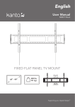
FIXED FLAT PANEL TV MOUNT
23” - 37”
100 lbs
(45 kg)
100 x 100
to
400 x 300
VESA
COMPLIANT
Supporting your digital lifestyle™
Table of Contents
Table of Contents / Introduction . . . . . . . . . . . . .
Supplied Parts & Hardware . . . . . . . . . . . . . . . . . .
Setup - Step 1 . . . . . . . . . . . . . . . . . . . . . . . . . . . .
Setup - Step 2 . . . . . . . . . . . . . . . . . . . . . . . . . . . .
2
3
4
5
Setup - Steps 3 to 4 . . . . . . . . . . . . . . . . . . . . . . . . 6
Other Kanto Products . . . . . . . . . . . . . . . . . . . . . . 7
Warranty . . . . . . . . . . . . . . . . . . . . . . . . . . . . . . . . 8
Introduction
Thank you for choosing a Kanto AV Systems wall mount. The F2337 is designed to mount flat panel televisions weighing
up to 100 lbs (45 kg) within 1” of your wall.
Read these instructions fully before installation of this mount. If you do not understand these directions, or have any
doubts about the safety of the installation, please consult a qualified installation contractor to install this mount. Make sure
there are no defective or missing parts. Do not use defective parts. If you are uncertain whether the part is defective call
Kanto AV Systems directly at 1-888-848-2643 or [email protected]. Kanto AV Systems can not be liable for property
damage or injury caused by incorrect mounting, incorrect assembly, lifting or incorrect use of this product.
This product should not be mounted on steel stud walls or cinder block walls. Consult a qualified installation contractor if
you are unsure about the type of wall you may have. We make every effort to ensure all necessary hardware is included. If
there is hardware missing please call Kanto AV Systems directly at 1-888-848-2643 or [email protected].
See installation video online at:
www.kantoav.com/pages/video-f2337
CAUTION
The maximum loading weight is 100 lbs (45 kg). This wall mount is intended for use only within the maximum
weight restrictions indicated. Use with products heavier than the maximum weights indicated may result in instability
causing possible injury. Recommended TV Size: 23 inch to 37 inch.
CAUTION
The wall you plan to affix the Kanto mount to must be able to support more than 5 times the weight of the
television and the wall mount combined. Do not use this product for any purpose other than to mount a flat panel
TV on a vertical surface as outlined in this manual. Improper installation may cause damage to your TV or serious
injury. This product should not be mounted to steel stud walls, cinder block or old concrete walls. Consult a qualified
installation contractor if you are unsure about the type of wall you may have.
2
Supplied Parts and Hardware
Wall Plate
x4
A: M4 x 15mm
Screw
x4
E: M6 x 15mm
Screw
x4
J: Washer
x4
B: M4 x 25mm
Screw
x4
F: M6 x 25mm
Screw
x4
x4
C: M5 x 15mm
Screw
D: M5 x 25mm
Screw
x4
G: M8 x 15mm
Screw
x4
K: Lag Bolt Washer
x4
x4
H: M8 x 25mm
Screw
I: M8 x 35mm
Screw
x4
L: Plastic Spacer
x4
x4
M: Lag Bolt
x2
R: Quick-Lock
TV Bracket
N: Concrete Anchor
Required Tools
• 3/16” wood drill bit
• hammer (for concrete installs)
• 7/16” masonry bit (for concrete installs) • carpenter’s level
• Socket set
• stud finder
• Phillips screwdriver
3
Supporting your digital lifestyle™
Step 1: Attach TV Brackets
There are a wide variety of TVs available offering an assortment of screw sizes. We provide a selection of mounting
screws to fit most TVs. If you have any concerns about this mounting hardware or installation call us direct at 1-888848-2643 or email at [email protected] .
Step 1.1 Select the correct size of bolt.
Step 1.2 Attach TV bracket arms to the back of the TV
Kanto provides 4 bolt diameters (Metric sizes M4, M5, M6
and M8) in various lengths.
Now that you have selected the correct bolt length, it’s
time to attach the arms to the TV, as shown in Diagram
A.
Part items: A, B, C, D, E, F, G, H, or I
Select the correct diameter screw and hand screw into
the back of the TV to determine the correct length. Use
the longest available bolt without reaching the bottom of
the TV threads.
Use the washer (J) for bolts A-F (sizes M4, M5 and M6).
The washer will work for all three screw sizes.
Please note: The washer is not required for M8 size bolts
(G, H & I).
If your TV has a curved back, you can use the spacers (L).
Quick-Lock TV bracket (R)
Screws (A thru I)
Quick-Lock TV bracket (R)
Washer (J) used
with screws A thru F
Diagram A
Spacer (L), if necessary
for curved TVs
WARNING
Never over-tighten a screw into the back of your flat panel TV.
Do not lay the TV face down on its glass front. Use a wall or a TV stand.
4
Step 2: Mount Wall Plate
Wood Stud Wall
Brick or Concrete Wall
The Wall Plate must be mounted to two wood studs. Use
a stud sensor to locate the two studs, clearly marking
the outer edges of the studs (see Diagram B). Use a long
level to ensure the two holes are level at the desired
height.
Using the Wall Plate as a template, mark four holes
toward the outer edge of the Wall Plate at your desired
height (see Diagram C). Adjust the Wall Plate position to
be clear of mortar joints, keeping in mind that the mount
provides minor horizontal shift along the length of the
Wall Plate. Use a long level to ensure the four holes are
level and at the desired height.
Pre-drill two upper holes in the center of your studs,
and attach the Wall Plate to the wall using 2 Lag Bolts
(M) and Lag Bolt Washers (K) (see Diagram B). Do not
over-tighten lag bolts (M). Make sure the Wall Plate is flat
against the wall surface. Using the Wall Plate as template,
pre-drill the bottom 2 holes, and secure using 2 Lag
Bolts (M) and 2 Lag Bolt Washers (K), taking care not to
over-tighten.
Wood
Pre-drill four holes, and insert a Concrete Anchor (N) into
each of the holes flush with the concrete wall surface and
not flush with the surface covering, such as drywall.
Attach the Wall Plate using 4 Lag Bolts (M) and Lag Bolt
Washers (K) (see Diagram C). Make sure the Wall Plate
is flat against the wall surface. Do not over-tighten
Lag Bolts (M).
Concrete
3” (75 mm)
3” (75 mm)
3/16”
(5 mm)
7/16”
(11mm)
N
K
K
M
Diagram B
CAUTION
Make sure the supporting surface will support
the load limits outlined in the Caution at bottom
of page two. Tighten Lag Bolts until the Wall Plate is
snug flat against the wall. Do not over tighten Lag Bolts
(M). Each Lag Bolt must be located in the center of a
wood stud.
5
M
Diagram C
CAUTION
Make sure the concrete or brick wall is at least
3.5” thick. Make sure the anchor is seated completely
flush with the concrete surface even if there is another
layer of material, such as drywall. If drywall is over 5/8”
thick custom lag bolts must be used. Concrete must be
a minimum of 2000psi in density.
™
Supporting
Supporting your
your digital
digital lifestyle
lifestyle™
CAUTION
Read this section carefully prior to install.
Step 3: Attach TV to Wall Plate
With the TV brackets firmly secured to the TV, use two
people to lift the TV into position and hook the TV brackets
onto the wall plate, as shown in Diagram D.
The two spring loaded Quick-Lock brackets will snap into
place as you lower the bottom of the TV onto the plate.
For minor level adjustment, you can adjust the two top
screws using a Phillips screwdriver to ensure the TV hangs
level, as shown in Diagram E. If you need to release pressure on the screws, pull down slightly on the Quick Release
cords as shown in Diagram F.
Level
Loosen
Hook
Pull
Cord to
Release
Diagram D
Diagram E
Diagram F
Step 4: Release the TV
Because the TV sits so close to your wall, the Quick-Lock TV
brackets are equipped with quick release cords. Loosen the
top levelling screws slightly to release tension, then simply
pull to release both Quick-Locks (as shown in Diagram F), and
pull the bottom of the TV away from the wall. Then, using two
people, lift the TV up and away from the wall plate.
WARNING
Use two people to lift and position the TV onto the Wall Plate.
6
Check out more great products from Kanto!
Kanto YARO Speaker System
• Our stunning new audio system designed for Apple TV
• Utilizing audio technology by Bang & Olufsen ICEpower
• 100 watts of pure clean sound
• Optional 200 watt sub-woofer
• Visit kantospeakers.com for more!
Kanto Infinity Series Cables
• 3D and 1080p HD Full Colour Capabilities
• 24 kt gold plated contacts
• Metal head connectors with flex relief and grip
• HDMI Ethernet Channel
For more TV and desktop mounts, along with our other
products, please visit kantoav.com.
“LIKE” Kanto on Facebook to receive upcoming news
and special product offers.
7
Supporting your digital lifestyle™
Warranty
Limited Warranty To Original Purchaser
Kanto AV Systems (Kanto) warrants the equipment it manufactures to be free from defects in material and workmanship for
the following limited warranty period of:
24 months parts and labour
If equipment fails because of such defects and Kanto or an authorized dealer is notified within 24 months from the date
of shipment with proof of original invoice. Kanto will, at its option, repair or replace the equipment, provided that the
equipment has not been subjected to mechanical, electrical, or other abuse or modifications. Equipment that fails under
conditions other than those covered will be repaired at the current price of parts and labor in effect at the repair. Such repairs
are warranted for 90 days from the day of reshipment to the original purchaser. This warranty is in lieu of all other warranties
expressed or implied, including without limitation, any implied warranty or merchantability or fitness for any particular
purpose, all of which are expressly disclaimed.
The information in the owner’s manual has been carefully checked and is believed to be accurate. However, Kanto assumes
no responsibility for any inaccuracies that may be contained in the manual. In no event will Kanto, be liable for direct, indirect,
special, incidental, or consequential damages resulting from any defect or omission in this manual, even if advised of the
possibility of such damages.
Rev 12-05
www.kantoav.com [email protected]
Tel 604.231.9574 Fax 604.231.9535