1
UM0549
User manual
STM3210E-EVAL demonstration software
Introduction
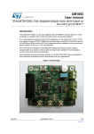
This user manual describes the demonstration firmware running on the STM3210E-EVAL
evaluation board. It can be used to evaluate the capabilities and on-board peripherals of the
high-density access line and performance line MCUs (STM32F101xC, STM32F101xD,
STM32F101xE, STM32F103xC, STM32F103xD, STM32F103xE).
The STM3210E-EVAL board is delivered with the demonstration and the DFU (device
firmware upgrade) programmed in the internal Flash memory, and all the files needed by the
demonstration are programmed in the NOR Flash memory. At each reset (board power-up,
external reset, etc.) the demonstration is executed. To run the DFU, the Key push-button
must be kept pressed at reset.
If the STM3210E-EVAL board was not factory-programmed, the demonstration application
was erased or the NOR Flash memory contents were modified, the DFU can be used to
program those files. For more details, refer to Section 2 and Section 3.
This demonstration firmware, the USB library, and other such firmware are available for
download from the STMicroelectronics website: www.st.com.
August 2010
Doc ID 14703 Rev 3
1/59
www.st.com
Contents
UM0549
Contents
1
Functional description . . . . . . . . . . . . . . . . . . . . . . . . . . . . . . . . . . . . . . . 7
1.1
Power control . . . . . . . . . . . . . . . . . . . . . . . . . . . . . . . . . . . . . . . . . . . . . . . 8
1.2
Clocking . . . . . . . . . . . . . . . . . . . . . . . . . . . . . . . . . . . . . . . . . . . . . . . . . . . 8
1.3
Reset control . . . . . . . . . . . . . . . . . . . . . . . . . . . . . . . . . . . . . . . . . . . . . . . 8
1.4
Debug JTAG interface . . . . . . . . . . . . . . . . . . . . . . . . . . . . . . . . . . . . . . . . 8
1.5
Serial wire debugger interface . . . . . . . . . . . . . . . . . . . . . . . . . . . . . . . . . . 8
1.6
Display devices . . . . . . . . . . . . . . . . . . . . . . . . . . . . . . . . . . . . . . . . . . . . . . 8
1.7
2
1.6.1
LCD . . . . . . . . . . . . . . . . . . . . . . . . . . . . . . . . . . . . . . . . . . . . . . . . . . . . . 8
1.6.2
LED . . . . . . . . . . . . . . . . . . . . . . . . . . . . . . . . . . . . . . . . . . . . . . . . . . . . . 8
Interfaces . . . . . . . . . . . . . . . . . . . . . . . . . . . . . . . . . . . . . . . . . . . . . . . . . . 8
1.7.1
RS232 . . . . . . . . . . . . . . . . . . . . . . . . . . . . . . . . . . . . . . . . . . . . . . . . . . . 8
1.7.2
CAN . . . . . . . . . . . . . . . . . . . . . . . . . . . . . . . . . . . . . . . . . . . . . . . . . . . . . 9
1.7.3
USB . . . . . . . . . . . . . . . . . . . . . . . . . . . . . . . . . . . . . . . . . . . . . . . . . . . . . 9
1.8
Motor control . . . . . . . . . . . . . . . . . . . . . . . . . . . . . . . . . . . . . . . . . . . . . . . 9
1.9
IrDA . . . . . . . . . . . . . . . . . . . . . . . . . . . . . . . . . . . . . . . . . . . . . . . . . . . . . . 9
1.10
Miscellaneous peripherals . . . . . . . . . . . . . . . . . . . . . . . . . . . . . . . . . . . . . 9
1.10.1
Joystick . . . . . . . . . . . . . . . . . . . . . . . . . . . . . . . . . . . . . . . . . . . . . . . . . . 9
1.10.2
Push-buttons . . . . . . . . . . . . . . . . . . . . . . . . . . . . . . . . . . . . . . . . . . . . . . 9
1.10.3
12-bit analog-to-digital converter (ADC) . . . . . . . . . . . . . . . . . . . . . . . . . 9
1.10.4
Audio . . . . . . . . . . . . . . . . . . . . . . . . . . . . . . . . . . . . . . . . . . . . . . . . . . . . 9
1.10.5
Storage memories . . . . . . . . . . . . . . . . . . . . . . . . . . . . . . . . . . . . . . . . . 10
1.10.6
Temperature sensor . . . . . . . . . . . . . . . . . . . . . . . . . . . . . . . . . . . . . . . . 10
1.10.7
STM3210E-EVAL board jumper configuration . . . . . . . . . . . . . . . . . . . . 10
Running the demonstration . . . . . . . . . . . . . . . . . . . . . . . . . . . . . . . . . . 11
2.1
2.2
2.3
Menu . . . . . . . . . . . . . . . . . . . . . . . . . . . . . . . . . . . . . . . . . . . . . . . . . . . . 11
2.1.1
Demo startup . . . . . . . . . . . . . . . . . . . . . . . . . . . . . . . . . . . . . . . . . . . . . 13
2.1.2
Navigation . . . . . . . . . . . . . . . . . . . . . . . . . . . . . . . . . . . . . . . . . . . . . . . 15
Clock sources . . . . . . . . . . . . . . . . . . . . . . . . . . . . . . . . . . . . . . . . . . . . . . 16
2.2.1
Clock control . . . . . . . . . . . . . . . . . . . . . . . . . . . . . . . . . . . . . . . . . . . . . 16
2.2.2
Clock failure . . . . . . . . . . . . . . . . . . . . . . . . . . . . . . . . . . . . . . . . . . . . . . 16
STM32F103ZE(T6) resources . . . . . . . . . . . . . . . . . . . . . . . . . . . . . . . . . 18
2.3.1
2/59
Peripherals . . . . . . . . . . . . . . . . . . . . . . . . . . . . . . . . . . . . . . . . . . . . . . . 18
Doc ID 14703 Rev 3
UM0549
Contents
2.4
3
4
2.3.2
Interrupts . . . . . . . . . . . . . . . . . . . . . . . . . . . . . . . . . . . . . . . . . . . . . . . . 19
2.3.3
External interrupts . . . . . . . . . . . . . . . . . . . . . . . . . . . . . . . . . . . . . . . . . 20
2.3.4
Internal memory size . . . . . . . . . . . . . . . . . . . . . . . . . . . . . . . . . . . . . . . 20
2.3.5
External memory size . . . . . . . . . . . . . . . . . . . . . . . . . . . . . . . . . . . . . . 20
Demo applications . . . . . . . . . . . . . . . . . . . . . . . . . . . . . . . . . . . . . . . . . . 21
2.4.1
Product presentation . . . . . . . . . . . . . . . . . . . . . . . . . . . . . . . . . . . . . . . 21
2.4.2
Calendar . . . . . . . . . . . . . . . . . . . . . . . . . . . . . . . . . . . . . . . . . . . . . . . . 23
2.4.3
Animation submenu . . . . . . . . . . . . . . . . . . . . . . . . . . . . . . . . . . . . . . . . 28
2.4.4
Wave Player submenu . . . . . . . . . . . . . . . . . . . . . . . . . . . . . . . . . . . . . . 30
2.4.5
USB mass storage . . . . . . . . . . . . . . . . . . . . . . . . . . . . . . . . . . . . . . . . . 34
2.4.6
Low-power modes . . . . . . . . . . . . . . . . . . . . . . . . . . . . . . . . . . . . . . . . . 36
2.4.7
Smartcard . . . . . . . . . . . . . . . . . . . . . . . . . . . . . . . . . . . . . . . . . . . . . . . 43
2.4.8
Thermometer . . . . . . . . . . . . . . . . . . . . . . . . . . . . . . . . . . . . . . . . . . . . . 46
2.4.9
Help submenu . . . . . . . . . . . . . . . . . . . . . . . . . . . . . . . . . . . . . . . . . . . . 47
2.4.10
About submenu . . . . . . . . . . . . . . . . . . . . . . . . . . . . . . . . . . . . . . . . . . . 49
Demonstration programming using the DFU . . . . . . . . . . . . . . . . . . . . 50
3.1
Programming the M29W128 NOR Flash memory . . . . . . . . . . . . . . . . . . 50
3.2
Demo programming . . . . . . . . . . . . . . . . . . . . . . . . . . . . . . . . . . . . . . . . . 54
Revision history . . . . . . . . . . . . . . . . . . . . . . . . . . . . . . . . . . . . . . . . . . . 58
Doc ID 14703 Rev 3
3/59
List of tables
UM0549
List of tables
Table 1.
Table 2.
Table 3.
Table 4.
4/59
STM32F103ZE(T6) demo peripherals . . . . . . . . . . . . . . . . . . . . . . . . . . . . . . . . . . . . . . . . 18
STM32F103ZE(T6) demo interrupts . . . . . . . . . . . . . . . . . . . . . . . . . . . . . . . . . . . . . . . . . . 19
STM32F103ZE(T6( demo external interrupts . . . . . . . . . . . . . . . . . . . . . . . . . . . . . . . . . . . 20
Document revision history . . . . . . . . . . . . . . . . . . . . . . . . . . . . . . . . . . . . . . . . . . . . . . . . . 58
Doc ID 14703 Rev 3
UM0549
List of figures
List of figures
Figure 1.
Figure 2.
Figure 3.
Figure 4.
Figure 5.
Figure 6.
Figure 7.
Figure 8.
Figure 9.
Figure 10.
Figure 11.
Figure 12.
Figure 13.
Figure 14.
Figure 15.
Figure 16.
Figure 17.
Figure 18.
Figure 19.
Figure 20.
Figure 21.
Figure 22.
Figure 23.
Figure 24.
Figure 25.
Figure 26.
Figure 27.
Figure 28.
Figure 29.
Figure 30.
Figure 31.
Figure 32.
Figure 33.
Figure 34.
Figure 35.
Figure 36.
Figure 37.
Figure 38.
Figure 39.
Figure 40.
Figure 41.
Figure 42.
Figure 43.
Figure 44.
Figure 45.
Figure 46.
Figure 47.
Figure 48.
Evaluation board overview . . . . . . . . . . . . . . . . . . . . . . . . . . . . . . . . . . . . . . . . . . . . . . . . . . 7
Structure of the demonstration menus . . . . . . . . . . . . . . . . . . . . . . . . . . . . . . . . . . . . . . . . 12
Warning message . . . . . . . . . . . . . . . . . . . . . . . . . . . . . . . . . . . . . . . . . . . . . . . . . . . . . . . . 13
ST Logo . . . . . . . . . . . . . . . . . . . . . . . . . . . . . . . . . . . . . . . . . . . . . . . . . . . . . . . . . . . . . . . 13
STM32 family . . . . . . . . . . . . . . . . . . . . . . . . . . . . . . . . . . . . . . . . . . . . . . . . . . . . . . . . . . . 13
Time and date configuration . . . . . . . . . . . . . . . . . . . . . . . . . . . . . . . . . . . . . . . . . . . . . . . . 14
Main menu . . . . . . . . . . . . . . . . . . . . . . . . . . . . . . . . . . . . . . . . . . . . . . . . . . . . . . . . . . . . . 14
Corresponding submenus. . . . . . . . . . . . . . . . . . . . . . . . . . . . . . . . . . . . . . . . . . . . . . . . . . 15
Navigating in the demonstration menus . . . . . . . . . . . . . . . . . . . . . . . . . . . . . . . . . . . . . . . 15
Clock tree diagram . . . . . . . . . . . . . . . . . . . . . . . . . . . . . . . . . . . . . . . . . . . . . . . . . . . . . . . 16
No HSE clock detected . . . . . . . . . . . . . . . . . . . . . . . . . . . . . . . . . . . . . . . . . . . . . . . . . . . . 17
Standby mode entered . . . . . . . . . . . . . . . . . . . . . . . . . . . . . . . . . . . . . . . . . . . . . . . . . . . . 17
Internal Flash memory organization . . . . . . . . . . . . . . . . . . . . . . . . . . . . . . . . . . . . . . . . . . 20
NOR Flash memory organization . . . . . . . . . . . . . . . . . . . . . . . . . . . . . . . . . . . . . . . . . . . . 20
Product presentation is ready to start . . . . . . . . . . . . . . . . . . . . . . . . . . . . . . . . . . . . . . . . . 21
First presentation slide . . . . . . . . . . . . . . . . . . . . . . . . . . . . . . . . . . . . . . . . . . . . . . . . . . . . 21
Last presentation slide . . . . . . . . . . . . . . . . . . . . . . . . . . . . . . . . . . . . . . . . . . . . . . . . . . . . 22
No loaded wave file . . . . . . . . . . . . . . . . . . . . . . . . . . . . . . . . . . . . . . . . . . . . . . . . . . . . . . 22
End of slide show . . . . . . . . . . . . . . . . . . . . . . . . . . . . . . . . . . . . . . . . . . . . . . . . . . . . . . . . 23
Setting the time and date . . . . . . . . . . . . . . . . . . . . . . . . . . . . . . . . . . . . . . . . . . . . . . . . . . 23
Time Adjust submenu . . . . . . . . . . . . . . . . . . . . . . . . . . . . . . . . . . . . . . . . . . . . . . . . . . . . . 24
Time Show submenu . . . . . . . . . . . . . . . . . . . . . . . . . . . . . . . . . . . . . . . . . . . . . . . . . . . . . 24
Setting the Year . . . . . . . . . . . . . . . . . . . . . . . . . . . . . . . . . . . . . . . . . . . . . . . . . . . . . . . . . 25
Setting the Month . . . . . . . . . . . . . . . . . . . . . . . . . . . . . . . . . . . . . . . . . . . . . . . . . . . . . . . . 26
Setting the day of the month . . . . . . . . . . . . . . . . . . . . . . . . . . . . . . . . . . . . . . . . . . . . . . . . 26
Exiting the Date Show submenu. . . . . . . . . . . . . . . . . . . . . . . . . . . . . . . . . . . . . . . . . . . . . 26
Setting the alarm activation time. . . . . . . . . . . . . . . . . . . . . . . . . . . . . . . . . . . . . . . . . . . . . 27
Alarm Show submenu. . . . . . . . . . . . . . . . . . . . . . . . . . . . . . . . . . . . . . . . . . . . . . . . . . . . . 27
The time and date need setting . . . . . . . . . . . . . . . . . . . . . . . . . . . . . . . . . . . . . . . . . . . . . 28
Animation submenu . . . . . . . . . . . . . . . . . . . . . . . . . . . . . . . . . . . . . . . . . . . . . . . . . . . . . . 28
STM32 Banner animation . . . . . . . . . . . . . . . . . . . . . . . . . . . . . . . . . . . . . . . . . . . . . . . . . . 29
Exit submenu . . . . . . . . . . . . . . . . . . . . . . . . . . . . . . . . . . . . . . . . . . . . . . . . . . . . . . . . . . . 29
STM32 Display Speed . . . . . . . . . . . . . . . . . . . . . . . . . . . . . . . . . . . . . . . . . . . . . . . . . . . . 30
Exit submenu . . . . . . . . . . . . . . . . . . . . . . . . . . . . . . . . . . . . . . . . . . . . . . . . . . . . . . . . . . . 30
Wave Player submenu . . . . . . . . . . . . . . . . . . . . . . . . . . . . . . . . . . . . . . . . . . . . . . . . . . . . 31
Wave Player interface. . . . . . . . . . . . . . . . . . . . . . . . . . . . . . . . . . . . . . . . . . . . . . . . . . . . . 31
Wave Player Playing submenu . . . . . . . . . . . . . . . . . . . . . . . . . . . . . . . . . . . . . . . . . . . . . . 32
Pause submenu . . . . . . . . . . . . . . . . . . . . . . . . . . . . . . . . . . . . . . . . . . . . . . . . . . . . . . . . . 32
Memory Error submenu . . . . . . . . . . . . . . . . . . . . . . . . . . . . . . . . . . . . . . . . . . . . . . . . . . . 33
I2C Communication Error submenu . . . . . . . . . . . . . . . . . . . . . . . . . . . . . . . . . . . . . . . . . . 33
Audio file Error submenu . . . . . . . . . . . . . . . . . . . . . . . . . . . . . . . . . . . . . . . . . . . . . . . . . . 34
USB Mass Storage submenu . . . . . . . . . . . . . . . . . . . . . . . . . . . . . . . . . . . . . . . . . . . . . . . 34
USB Mass Storage submenu selected . . . . . . . . . . . . . . . . . . . . . . . . . . . . . . . . . . . . . . . . 35
USB cable connected . . . . . . . . . . . . . . . . . . . . . . . . . . . . . . . . . . . . . . . . . . . . . . . . . . . . . 35
NAND Erase operation . . . . . . . . . . . . . . . . . . . . . . . . . . . . . . . . . . . . . . . . . . . . . . . . . . . . 36
NAND Flash Erase operation completed . . . . . . . . . . . . . . . . . . . . . . . . . . . . . . . . . . . . . . 36
Exiting the Stop mode. . . . . . . . . . . . . . . . . . . . . . . . . . . . . . . . . . . . . . . . . . . . . . . . . . . . . 37
Stop mode entered . . . . . . . . . . . . . . . . . . . . . . . . . . . . . . . . . . . . . . . . . . . . . . . . . . . . . . . 37
Doc ID 14703 Rev 3
5/59
List of figures
Figure 49.
Figure 50.
Figure 51.
Figure 52.
Figure 53.
Figure 54.
Figure 55.
Figure 56.
Figure 57.
Figure 58.
Figure 59.
Figure 60.
Figure 61.
Figure 62.
Figure 63.
Figure 64.
Figure 65.
Figure 66.
Figure 67.
Figure 68.
Figure 69.
Figure 70.
Figure 71.
Figure 72.
Figure 73.
Figure 74.
Figure 75.
Figure 76.
Figure 77.
Figure 78.
Figure 79.
Figure 80.
Figure 81.
Figure 82.
Figure 83.
6/59
UM0549
MCU in the Stop mode . . . . . . . . . . . . . . . . . . . . . . . . . . . . . . . . . . . . . . . . . . . . . . . . . . . . 38
RTC Alarm causes the MCU to exit the Stop mode . . . . . . . . . . . . . . . . . . . . . . . . . . . . . . 38
Setting the Wakeup time. . . . . . . . . . . . . . . . . . . . . . . . . . . . . . . . . . . . . . . . . . . . . . . . . . . 39
RTC Alarm wakeup configured . . . . . . . . . . . . . . . . . . . . . . . . . . . . . . . . . . . . . . . . . . . . . . 39
RTC Alarm wakeup. . . . . . . . . . . . . . . . . . . . . . . . . . . . . . . . . . . . . . . . . . . . . . . . . . . . . . . 39
Time and Date configuration prompt . . . . . . . . . . . . . . . . . . . . . . . . . . . . . . . . . . . . . . . . . 40
Entering the Standby mode . . . . . . . . . . . . . . . . . . . . . . . . . . . . . . . . . . . . . . . . . . . . . . . . 40
MCU in Standby mode . . . . . . . . . . . . . . . . . . . . . . . . . . . . . . . . . . . . . . . . . . . . . . . . . . . . 41
RTC Alarm causes the MCU to exit the Standby mode . . . . . . . . . . . . . . . . . . . . . . . . . . . 41
Setting the wakeup time . . . . . . . . . . . . . . . . . . . . . . . . . . . . . . . . . . . . . . . . . . . . . . . . . . . 42
RTC Alarm wakeup configured . . . . . . . . . . . . . . . . . . . . . . . . . . . . . . . . . . . . . . . . . . . . . . 42
Time and Date configuration prompt . . . . . . . . . . . . . . . . . . . . . . . . . . . . . . . . . . . . . . . . . 43
Smartcard submenu - 1 . . . . . . . . . . . . . . . . . . . . . . . . . . . . . . . . . . . . . . . . . . . . . . . . . . . 43
Smartcard submenu - 2 . . . . . . . . . . . . . . . . . . . . . . . . . . . . . . . . . . . . . . . . . . . . . . . . . . . 44
Smartcard submenu - 3 . . . . . . . . . . . . . . . . . . . . . . . . . . . . . . . . . . . . . . . . . . . . . . . . . . . 44
Smartcard ATR decoded . . . . . . . . . . . . . . . . . . . . . . . . . . . . . . . . . . . . . . . . . . . . . . . . . . 44
Smartcard ATR . . . . . . . . . . . . . . . . . . . . . . . . . . . . . . . . . . . . . . . . . . . . . . . . . . . . . . . . . . 45
Smartcard Error message. . . . . . . . . . . . . . . . . . . . . . . . . . . . . . . . . . . . . . . . . . . . . . . . . . 45
Noncompatible smartcard error message. . . . . . . . . . . . . . . . . . . . . . . . . . . . . . . . . . . . . . 46
Thermometer submenu selected . . . . . . . . . . . . . . . . . . . . . . . . . . . . . . . . . . . . . . . . . . . . 46
Temperature display . . . . . . . . . . . . . . . . . . . . . . . . . . . . . . . . . . . . . . . . . . . . . . . . . . . . . . 47
Temperature sensor error . . . . . . . . . . . . . . . . . . . . . . . . . . . . . . . . . . . . . . . . . . . . . . . . . . 47
Help submenu. . . . . . . . . . . . . . . . . . . . . . . . . . . . . . . . . . . . . . . . . . . . . . . . . . . . . . . . . . . 48
Joystick buttons . . . . . . . . . . . . . . . . . . . . . . . . . . . . . . . . . . . . . . . . . . . . . . . . . . . . . . . . . 48
Second Help slide . . . . . . . . . . . . . . . . . . . . . . . . . . . . . . . . . . . . . . . . . . . . . . . . . . . . . . . . 48
About submenu. . . . . . . . . . . . . . . . . . . . . . . . . . . . . . . . . . . . . . . . . . . . . . . . . . . . . . . . . . 49
Programming the NOR Flash memory . . . . . . . . . . . . . . . . . . . . . . . . . . . . . . . . . . . . . . . . 51
Selecting the STM3210E-EVAL_Demo_NORFlash_V1.0.dfu file . . . . . . . . . . . . . . . . . . . 52
Click Yes to continue . . . . . . . . . . . . . . . . . . . . . . . . . . . . . . . . . . . . . . . . . . . . . . . . . . . . . 52
NOR Flash memory programming . . . . . . . . . . . . . . . . . . . . . . . . . . . . . . . . . . . . . . . . . . . 53
Programming the demo . . . . . . . . . . . . . . . . . . . . . . . . . . . . . . . . . . . . . . . . . . . . . . . . . . . 54
Selecting the STM3210E-EVAL_Demo_V1.0.dfu file . . . . . . . . . . . . . . . . . . . . . . . . . . . . . 55
Click Yes to continue . . . . . . . . . . . . . . . . . . . . . . . . . . . . . . . . . . . . . . . . . . . . . . . . . . . . . 55
Internal Flash memory programming . . . . . . . . . . . . . . . . . . . . . . . . . . . . . . . . . . . . . . . . . 56
DFU mode left. . . . . . . . . . . . . . . . . . . . . . . . . . . . . . . . . . . . . . . . . . . . . . . . . . . . . . . . . . . 57
Doc ID 14703 Rev 3
UM0549
Functional description
The STM32F103ZE(T6) microcontroller evaluation board provides a development and
demonstration platform for STM32F103xx-based applications. It is designed to allow the
user to try out the major functions of the STM32F103ZE(T6) microcontroller.
Figure 1 summarizes the main functional blocks of the evaluation board.
Figure 1.
Evaluation board overview
3.3 V voltage
regulator
I2S
512 Kbit × 16
SRAM
GPIO
512 Mbit
NAND Flash
128 Mbit
NOR Flash
FSMC
1
Functional description
STM32F103ZE(T6)
TFT LCD
64 Mbit or 128 Mbit
Serial Flash memory
MC control
connector
MicroSD card
Temperature sensor
SPI1
QST
connector
Extension
connector
for GPIOs
RS232
Tranceiver
USART1
DB9 connector
USART2
RS232
Tranceiver
USART2
DB9 connector
IrDA
Tranceiver
USART3
Smartcard
interface
I2C
JTAG
LEDs Key
and Joystick
USART1
MC
SDIO
Audio DAC
CAN
CAN
tranceiver
ADC
3 BNC
connector
Smartcard
connector
CAN DB9
connector
Debug
TRACE
Potentiometer
USB
USB type B
connector
ai15160
Doc ID 14703 Rev 3
7/59
Functional description
1.1
UM0549
Power control
The evaluation board can be powered from an external 5 V supply or from the USB
connector, all other required voltages are provided by on-board voltage regulators.
1.2
Clocking
Two clock sources are available on the STM3210E-EVAL evaluation board:
1.3
●
32 kHz crystal for embedded RTC
●
8 MHz crystal for STM32F103ZE
Reset control
The reset can be generated by hardware or software:
1.4
●
Reset button: activates the RESET input when pressed
●
JTAG reset
Debug JTAG interface
Software debug is done via the standard ARM® JTAG connection: 20-pin IDC (insulation
displacement connector) for connection to the standard ARM host interface.
1.5
Serial wire debugger interface
The Serial Wire Debug Port (SWD-DP) provides a 2-pin (clock + data) interface to the AHPAP port.
1.6
Display devices
1.6.1
LCD
A color LCD module is mounted on the STM3210E-EVAL board. It is interfaced through the
embedded FSMC controller.
1.6.2
LED
Four general-purpose LEDs are available. They are used as a display.
1.7
Interfaces
1.7.1
RS232
The STM32F103ZE evaluation board (STM3210E-EVAL) provides two on-board RS-232
serial ports. Both RS232 ports are accessed via DB9 connectors.
8/59
Doc ID 14703 Rev 3
UM0549
1.7.2
Functional description
CAN
The STM3210E-EVAL evaluation board supports CAN 2.0 A/CAN 2.0 B-compliant CAN bus
communication based on a 3.3 V CAN transceiver. Both the high-speed mode and the
slope-control mode are available. They are selected by setting a dedicated jumper.
1.7.3
USB
The STM3210E-EVAL evaluation board supports full-speed USB 2.0 communication thanks
to its embedded USB peripheral.
1.8
Motor control
The STM3210E-EVAL evaluation board supports inductor motor control via a 34-pin
connector that provides all required control and feedback signals to and from the motor
power-driving board.
1.9
IrDA
The STM3210E-EVAL evaluation board supports IrDA communication. The interface is
mounted on USART3.
1.10
Miscellaneous peripherals
1.10.1
Joystick
Four-direction joystick with a selection key.
1.10.2
Push-buttons
The following push-buttons are provided:
1.10.3
●
Key: user push-button
●
Tamper: user push-button
●
Wakeup: push-button used to wake up the processor from a low-power mode
12-bit analog-to-digital converter (ADC)
Varistor: ADC channel3 connected to an on-board variable resistor. The variable resistor
provides a voltage in the range of 0 V to 3.3 V.
Moreover, three BNC connectors are available for analog input.
1.10.4
Audio
The STM3210E-EVAL evaluation board implements a dedicated audio DAC with an I2S
interface. For the audio output, a speaker and an audio Jack are available on the board and
connected to the DAC.
Doc ID 14703 Rev 3
9/59
Functional description
1.10.5
UM0549
Storage memories
The STM3210E-EVAL evaluation board has five different storage memories: an SPI Flash
memory of 8 Mbyte connected to the SPI1 peripheral, an MSD (mass storage device) of 128
Mbyte connected to the SDIO peripheral, a 1 Mbyte SRAM, a 64 Mbyte NAND Flash
memory and a 16 Mbyte NOR Flash memory. The SRAM, the NAND Flash memory and the
NOR Flash memory are connected together to the FSMC interface.
1.10.6
Temperature sensor
The STM3210E-EVAL evaluation board includes an I2C temperature sensor connected to
the I2C1 peripheral.
1.10.7
STM3210E-EVAL board jumper configuration
To be able to run the STM3210E-EVAL demo correctly, configure the following STM3210EEVAL board jumpers as follows:
10/59
●
I2S MCLK JP18: position 2<->3
●
Smartcard JP15: fitted
●
Smartcard JP16: fitted
●
SD Card JP17: fitted
●
SD Card JP20: open
●
USB JP14: position 2<->3
●
NAND JP7: position 1<->2
●
JP4: position 1<->2
Doc ID 14703 Rev 3
UM0549
Running the demonstration
2
Running the demonstration
2.1
Menu
Figure 2 shows the menu system of the STM32F103ZE demonstration. The main menu is
shown on the left-hand side. The UP, DOWN, RIGHT and LEFT joystick directions allow the
user to navigate between items in the main menu and the submenus. To enter a submenu,
press the SEL push-button (SEL push-button is the switch closure that occurs when the
joystick button is pushed). To exit a submenu select the Return menu and press SEL.
Doc ID 14703 Rev 3
11/59
Running the demonstration
Figure 2.
UM0549
Structure of the demonstration menus
Product presentation
Start
Return
Adjust
Time
Show
Return
Adjust
STM32F10xxx Welcome message
Date
Calendar
Show
Return
Adjust
Alarm
Show
Return
Main menu
Return
STM32 banner
Animation
STM32 display speed
Return
Wave player
Wave player
Return
Start
USB mass storage
NAND physical format
Return
Exit: EXTI
Stop
Exit: RTC Alarm
Return
Exit: Wakeup pin
Low-power modes
Standby
Exit: RTC Alarm
Return
Return
Smartcard interface
Smartcard
Return
Thermometer
Temperature
Return
Help
Help
Return
About
About
Return
ai15161
12/59
Doc ID 14703 Rev 3
UM0549
2.1.1
Running the demonstration
Demo startup
After a board reset, at demo startup, the icons and bitmap files are checked in the NOR
Flash memory. All the icons have to be correctly programmed in the NOR Flash memory for
the demo to start, so if an icon is missing, the demo will not start and the message shown in
Figure 3 is displayed on the LCD screen.
Figure 3.
Warning message
However, if the icons are correctly loaded into the NOR Flash memory, the Welcome screen
is displayed and the ST Logo appears on the LCD (see Figure 4).
Figure 4.
ST Logo
Then, after 1 second, the following STM32 slide is displayed on the LCD screen as shown in
Figure 5.
Figure 5.
STM32 family
When the board is powered up for the first time and no power supply on VBAT is detected
(Battery), the user is prompted to set the time, year, month and day. The user may choose to
ignore it by pressing any key except for the SEL push-button to abort the configuration
Doc ID 14703 Rev 3
13/59
Running the demonstration
UM0549
sequence. To set the time and date, the user should press SEL and follow the setting
sequence.
The message shown in Figure 6 appears on the LCD screen.
Figure 6.
Note:
Time and date configuration
1
If the user chooses to configure the time and date, the Time Adjust and Date Adjust
menus are displayed. Otherwise the main menu is displayed and the user can set the time
parameters in the Calendar menu. To set the time/date use the joystick up/down and SEL
push-buttons.
2
If the time configuration has already been done, then the number of elapsed days (higher
than 1 day) from the last time the demo board was powered up appears on the LCD screen.
It is soon followed by the current date.
Once the time/date have been set, the main menu appears. The main menu is displayed in
the form of a set of icons. It presents all the submenus in the same screen. The user can
navigate using the UP, DOWN, RIGHT and LEFT joystick directions to select the desired
submenu. To enter the desired submenu, the user has to press the SEL joystick pushbutton, and the new submenu corresponding to the selected icon is displayed.
Figure 7.
Main menu
APP Main Menu Name
1. The icons shown in Figure 7 are taken from http://commons.wikimedia.org/wiki/Crystal_Clear.
Once a submenu has been selected, the name of the application is listed at the top of the
display and all the corresponding submenus are listed below as shown in Figure 8.
14/59
Doc ID 14703 Rev 3
UM0549
Running the demonstration
Figure 8.
Navigation
The demonstration menu is based on circular navigation, submenu selection, item selection
and back capability as described in Figure 9.
Left
Item 9
Right
Left
Down
Item 10
Up
Up
Right
Item 8
Left
Right
Item 11
Left
Item 3.1
Right
Item 12 Right
Left
Down
Down
Up
Down
Right
Item 7
Left
Right
Up
Right
Up
Down
Up
Item 6
Item 4
Left
Down
Left
Right
Item 3
Left
Up
Right
Down
Up
Item 5
Right
Up
Item 2
Down
Left
Up
Left
Right
Down
Item 1
Down
Left
Up
Navigating in the demonstration menus
Up
Figure 9.
Down
2.1.2
Corresponding submenus
Down
Select
Item 3.1.1
ect
l
Se
Item 3.2
ect
Sel
Item 3
...
Item 3.1.2
...
Item 3.1.n
Item 3.n
Return
Return
ai15162
The user navigates using the joystick push-buttons located on the evaluation board: RIGHT,
LEFT, SEL, UP and DOWN.
●
the UP, DOWN, RIGHT and LEFT push-buttons are used to perform circular navigation
in the main menu and the current menu items
●
the SEL push-button selects the current item
●
the UP and DOWN push-buttons are used for vertical navigation in the submenus
●
to return to the upper menu, go to the Return line and press SEL
Doc ID 14703 Rev 3
15/59
Running the demonstration
UM0549
2.2
Clock sources
2.2.1
Clock control
The STM32F103ZE’s internal clocks are derived from the HSE (clocked by the external
8 MHz crystal).
In this demo application, the different system clocks are configured as follows:
●
System clock is set to 72 MHz: the PLL is used as the system clock source: 72 MHz (two wait
states, Flash memory prefetch buffer enabled).
●
HCLK frequency is set to 72 MHz
●
Timer clock (TIMCLK) is set to 72 MHz
●
PCLK1 is set to 36 MHz
●
PCLK2 is set to 72 MHz
●
USB clock (USBCLK) is set to 48 MHz (internal clock: PLLCLK / 1.5)
Only the RTC is clocked by a 32 kHz external oscillator.
Figure 10. illustrates the clock tree organization for this demo.
Figure 10. Clock tree diagram
APB1 prescaler
/2, 4, 8, 16
PLL
×16...×2, ×3, ×4
8 MHz
AHB prescaler
/1, 2...512
APB2 prescaler
/2, 4, 8, 16
LSE
oscillator
32 kHz
72 MHz
HSE
oscillator
SYSCLK
8 MHz × 9 =
72 MHz
36 MHz
USB prescaler
/1, 1.5
PCLK1 to APB1
peripherals
TIM2, 3, 4, 5, 6, 7
×1, 2 multiplier
48 MHz
36 MHz
36 × 2 = 72 MHz
PCLK2 to APB2
peripherals
72 MHz
TIM1, TIM8
×1, 2 multiplier
72 MHz
RTC
32 kHz
ai15163
2.2.2
Clock failure
At any demo level, if no clock is present on OSC_IN (broken or disconnected crystal), the
message shown in Figure 11 is displayed on the LCD screen.
16/59
Doc ID 14703 Rev 3
UM0549
Running the demonstration
Figure 11. No HSE clock detected
If the 8 MHz Crystal is not reconnected in the next few seconds, the MCU enters the
Standby mode. If the 8 MHz crystal is reconnected within a few seconds, a system reset is
generated.
Note:
The clock security system (CSS) feeds the MCU with the HSI OSC used as an emergency
clock if no clock is detected.
When a timeout occurs, the MCU enters the Standby mode and the message shown in
Figure 12 is displayed on the LCD screen.
Figure 12. Standby mode entered
1. The demo will not restart as long as the 8 MHz crystal is not present.
2. Connecting the 8 MHz crystal after reset may not restart the demo correctly. The crystal must be
connected before starting the demo.
Doc ID 14703 Rev 3
17/59
Running the demonstration
UM0549
2.3
STM32F103ZE(T6) resources
2.3.1
Peripherals
All used peripherals are described in Table 1.
Table 1.
STM32F103ZE(T6) demo peripherals
Used peripherals
18/59
Application
I2C1
Temperature sensor
BKP
Calendar + Demo kernel
EXTI
Menu navigation + joystick + Push Button + low-power modes
GPIO
All applications + LEDs
NVIC
All applications using interrupts
PWR
Low-power modes
RCC
All applications + Demo kernel
RTC
Calendar
SPI1
SPI Flash
SysTick
Generate 10 ms time base
TIM1
LED toggling
FSMC
Color LCD + NAND Flash + NOR Flash
SDIO
MSD
SPI2 (I2S)
Audio codec
Doc ID 14703 Rev 3
UM0549
2.3.2
Running the demonstration
Interrupts
Table 2 shows all the enabled interrupts.
Table 2.
STM32F103ZE(T6) demo interrupts
Interrupts
Priority
Used for
SysTick
Preemption: 0
SubPriority: 0
System timing
RTC
Preemption: 0
SubPriority: 0
Calendar, date update
NMI
Preemption(fixed): -2
CSS interrupt
EXTI3
Preemption: 2
SubPriority: 1
Menu navigation
EXTI9_5
Preemption: 2
SubPriority: 1
Menu navigation
EXTI15_10
Preemption: 2
SubPriority: 0
Menu navigation
USB_LP_CAN_RX0
Preemption: 1
SubPriority: 0
USB Mass Storage
USB_HP_CAN_TX
Preemption: 0
SubPriority: 1
USB Mass Storage
TIM1_UP
Preemption: 1
SubPriority: 3
LED toggling
RTCAlarm
Preemption: 1
SubPriority: 1
Alarm generation
SPI2
Preemption: 0
SubPriority: 0
Audio data transfer
Doc ID 14703 Rev 3
19/59
Running the demonstration
2.3.3
UM0549
External interrupts
Table 3.
STM32F103ZE(T6( demo external interrupts
External interrupts
2.3.4
Used for
EXTI line3
Joystick DOWN (interrupt mode, falling edge)
EXTI line15
Joystick UP (interrupt mode, falling edge)
EXTI line7
Joystick SEL (interrupt mode, falling edge)
EXTI line8
User Button (interrupt mode, falling edge)
EXTI line17
RTC Alarm (interrupt mode, rising edge)
Internal memory size
Figure 13. Internal Flash memory organization
0x0807 FFFF
STM3210E-EVAL
Demo
0x0800 3000
0x0800 0000
USB DFU Demo
ai15164
2.3.5
External memory size
Figure 14. NOR Flash memory organization
0x64FF FFFF
0x64FC AC7E
Icons
Product slides
0x64D7 285E
STM32 animation
0x6461 EB7A
Product speech
0x6406 0000
0x6400 0000
Free space
ai15165
20/59
Doc ID 14703 Rev 3
UM0549
2.4
Running the demonstration
Demo applications
The following section provides a detailed description of each part of the demonstration.
Note:
2.4.1
1
In the demonstration, the core runs at HCLK = 72 MHz.
2
Four LEDs: LD1, LD2, LD3 and LD4 flash throughout the demonstration at a frequency
depending on the core clock.
Product presentation
This part of the demo is dedicated to the listing of all the embedded STM32F103ZE(T6)
peripherals and features. This presentation of the microcontroller is made with a set of
slides accompanied by a speech. Each slide is associated with a dedicated speech. When
the user starts the product presentation, the first slide appears and the corresponding
speech starts. Once the speech is finished, the second slide is displayed accompanied by
its speech and so on until the last slide.
When the Product presentation menu is selected, the message shown in Figure 15 is
displayed on the LCD screen.
Figure 15. Product presentation is ready to start
Product presentation slides
The set of slides is composed of 14 slides where all features and advantages of the
STM32F103ZE(T6) are listed. Figure 16 and Figure 17 show the first and last slides,
respectively.
Figure 16. First presentation slide
Doc ID 14703 Rev 3
21/59
Running the demonstration
UM0549
Figure 17. Last presentation slide
Product presentation speech
The High-density STM32F103xx microcontroller has two embedded SPI peripherals that
can be used in I2S mode for audio communication. An external audio codec is implemented
on the evaluation board in order to allow speech audio files to be played through the
embedded speaker or headphone.
The properties of the product presentation speech wave file are the following:
Note:
●
Playing time: 6 min 16s
●
File size: 6 024 058 bytes
●
Format tag: PCM
●
Channels: Mono
●
Sample rate: 8 kHz
●
Bits per sample: 16 bits
If the wave file of the promotion presentation speech is not loaded in the dedicated memory,
the message shown in Figure 18 is displayed on the LCD screen.
Figure 18. No loaded wave file
ERROR:
Wave File
End
of No
slide
show
Press joystick
to
Click
to exit
exit...
To stop the product presentation slide show and speech, push the SEL push-button. The
message shown in Figure 19 is displayed.
22/59
Doc ID 14703 Rev 3
UM0549
Running the demonstration
Figure 19. End of slide show
End of slide show
Exit: Push joystick
At the end of the product presentation or if the presentation was stopped, simply press any
joystick key to exit and return to the Product Presentation submenu.
2.4.2
Calendar
The STM32F103ZE(T6) features a real-time clock (RTC) that provides a set of continuously
running counters. These can be used, with suitable software, to implement a clock-calendar
function. The counter values can be written to set the current time of the system.
This submenu is used to configure the time, date and alarm. The date, time and alarm
settings are not lost when the board is powered off owing to the battery connected to the
VBAT pin. The VBAT pin supplies power to the RTC unit, allowing the RTC to operate even
when the main digital supply (VDD) is turned off.
Note:
To be able to use the battery to back up the RTC, the JP1 jumper must be in the position 12 in the STM3210E-EVAL board.
In any submenu, if the time and date parameters have not yet been configured, the
message shown in Figure 20 is displayed on the LCD screen.
Figure 20. Setting the time and date
The user has the choice to set or not the time, year, month and day. Press any key (except
for SEL) to ignore the prompt and abort the configuration sequence. Press on SEL and
follow the setting sequence to set the time and date.
Doc ID 14703 Rev 3
23/59
Running the demonstration
UM0549
Time submenu
This submenu is divided into two items that allow the user to display or set the current time.
●
Time Adjust: After the evaluation board is powered up, the user has to select this
submenu to change the default time (00:00:00) to the current time. Once “Time Adjust”
has been selected, the first digit of the hour field can be changed. Pressing the “UP”
button will display the current value plus one. Pressing the “DOWN” button will display
the previous digit value. After setting the digit value, press “SEL”, the cursor
automatically jumps to the next digit. When all the time digits have been set, the “Time”
submenu appears. Some digit values are limited to a range of values depending on the
field (hour, minute or seconds). The following message (with the default time or the
current time) is displayed on the LCD when this submenu is selected.
Figure 21. Time Adjust submenu
●
Time Show: this item displays the current time. If time and date have not been
configured before, a message is displayed, that gives the choice to set the time and
date or, to exit to the upper submenu. When this submenu is selected, the message
shown in Figure 22 appears on the LCD. In the example, the time has not been set yet.
Figure 22. Time Show submenu
To exit the Time Show submenu press the SEL push-button. To exit Time submenu select
the Return line and press the SEL push-button.
24/59
Doc ID 14703 Rev 3
UM0549
Running the demonstration
Date submenu
This submenu is divided into two items that allow the user to display or set the current date.
●
Date Adjust: this item has to be selected after each power-up in order to set the
current date. If the time and date have not been configured before, a message is
displayed, that gives the choice to set the time and date or, to exit to the upper
submenu. The user is asked to set the current date to be stored in the application
memory. The date is displayed as Year, Month, Week Nbr, Day Nbr (number of the
day in the year) with the selected day shown in the month. There is no default date
since the user has to set the date at least once. Once the submenu has been selected,
the user starts by setting the Year, then the Month and the day of the selected month.
The Month and the Year are selected using the UP or DOWN push-button. For the day,
the UP, DOWN, RIGHT and LEFT push-buttons can be used. Pressing the UP pushbutton will display the current value plus one, pressing the DOWN push-button will
display the previous value. To confirm the selected month, the user has to press the
SEL push-button and an automatic jump to the year configuration takes place. The
same procedure is applicable for the year configuration. After configuring the day,
pressing the SEL push-button will store the entered value and exit to the Date
submenu. The current date value is then shown and the user can change the setting if
required. The messages shown in Figure 23, Figure 24 and Figure 25 are successively
displayed on the LCD when this submenu is selected.
Figure 23. Setting the Year
Doc ID 14703 Rev 3
25/59
Running the demonstration
UM0549
Figure 24. Setting the Month
Figure 25. Setting the day of the month
– Date Show: this item displays the current date. If the time and date have not been
configured before, a message is displayed, that gives the choice to set the time and
date or, to exit to the upper submenu. The message shown in Figure 26 is displayed
on the LCD when the submenu is selected (with the date already configured).
Figure 26. Exiting the Date Show submenu
To exit this submenu press the SEL push-button. To exit the Date submenu, select the
Return line and press the SEL push-button.
26/59
Doc ID 14703 Rev 3
UM0549
Running the demonstration
Alarm submenu
Using this submenu, the user can configure the alarm activation time. When the alarm time
value is reached, all the LEDs (LED1 to LED4) start flashing together and so for 30 seconds.
This submenu is divided into two items to display or set the current alarm.
●
Alarm Adjust: the alarm time activation is set in the same way as the time is set in the
Time Adjust submenu. The following messages are successively displayed on the
LCD when this submenu is selected:
Figure 27. Setting the alarm activation time
●
Alarm Show: this item displays the current alarm time. The default Alarm activation
time displayed after power-up and before setting in the Alarm Adjust submenu is
00:00:00. If the time and date have not been configured before, a message shown in
Figure 29 is displayed, when you press select it takes you back to the Alarm submenu.
The message shown in Figure 28 is displayed on the LCD when this submenu is
selected.
Figure 28. Alarm Show submenu
To exit the Alarm Show submenu press the SEL push-button. To exit the Alarm submenu,
select the Return line and press the SEL push-button.
Note:
In the Alarm Adjust and Alarm Show menus, if the time and date have not yet been
configured, the message shown in Figure 29 is displayed on the LCD screen.
Doc ID 14703 Rev 3
27/59
Running the demonstration
UM0549
Figure 29. The time and date need setting
2.4.3
Animation submenu
The STM32F103ZE(T6) microcontroller provides an FSMC memory interface that is used
with a parallel LCD.
The Animation submenu is used to demonstrate the LCD control performance using the
embedded FSMC interface. The application is a successive display of stored images. The
result is a video-like animation.
Figure 30. Animation submenu
Animation
STM32 Banner
STM32 Display Speed
Return
STM32 Banner
This STM32 Banner animation is composed of fifty images. These images are displayed at a
rate equal to 12 frames per second (fps).
When the STM32 Banner menu is selected, the animation shown in Figure 31 is displayed
on the LCD screen.
28/59
Doc ID 14703 Rev 3
UM0549
Running the demonstration
Figure 31. STM32 Banner animation
Once the STM32 Banner Animation submenu has been selected, the relative animation is
displayed in a loop on the LCD screen.
If the SEL push-button is pressed while the animation is playing, the animation is stopped
and the submenu shown in Figure 32. is displayed.
Figure 32. Exit submenu
Exit: Push JoyStick
If any push-button is pressed, the application returns to the Animation menu.
STM32 Display Speed
This submenu displays the set of STM32 presentation slides composed of 14 slides with a
speed controlled through the RV1 trimmer. Increase or decrease the delay between two
frames by adjusting RV1: the maximum delay is of about 1s when RV1 is at its maximum
position.
When the STM32 Display Speed menu is selected, the animation shown in Figure 33 is
displayed on the LCD screen.
Doc ID 14703 Rev 3
29/59
Running the demonstration
UM0549
Figure 33. STM32 Display Speed
If the SEL push-button is pressed while the animation is playing, the animation is stopped
and the Exit submenu shown in Figure 34. is displayed.
Figure 34. Exit submenu
Exit: Push JoyStick
2.4.4
Wave Player submenu
The STM32F103ZE(T6) microcontroller provides SPI peripherals that support the I2S mode.
The Wave Player submenu is used to demonstrate the I2S feature. An audio codec is
connected to the I2S interface to play a stored wave file.
By selecting Wave Player, the submenu shown in Figure 35. is displayed.
30/59
Doc ID 14703 Rev 3
UM0549
Running the demonstration
Figure 35. Wave Player submenu
Wave Player
Wave Player
Return
When Start is selected the wave player interface is displayed as shown in Figure 36.
Figure 36. Wave Player interface
Wave Player
Control Buttons:
Up > Speaker
DOWN > Headphone
Stopped
vol
-
+
When the Wave Player starts, by default, the audio stream is stopped. In Figure 36, the
active push-buttons and their functions are displayed below “Control Buttons”. For example,
at start-up, pressing the “Up” JoyStick push-button causes the file to be played through the
embedded speaker, whereas pressing the “Down” push-button causes the file the file to be
played through the Headphone (in which case a headphone needs to be connected to the
audio jack implemented on the evaluation board).
Once the play command is prompted, the submenu shown in Figure 37. is displayed.
Doc ID 14703 Rev 3
31/59
Running the demonstration
UM0549
Figure 37. Wave Player Playing submenu
Wave Player
Control Buttons:
Up> Vol+
KEY> Pause
SEL> Stop
DOWN> VolPlaying
vol
+
-
The Progress bar and the Volume bar are displayed at the bottom of the Wave Player
Playing submenu. The Progress bar is updated every ~1% of the audio file duration and the
Volume bar is updated each time the volume level is changed.
At this application level, pressing:
–
the Key push-button pauses the audio stream
–
the SEL push-button stops the audio stream
–
the Up push-button increases the audio volume
–
the Down push-button decreases the audio volume
When the audio stream is paused, the menu in Figure 38 is displayed.
Figure 38. Pause submenu
Control Buttons:
Up> SPKR
KEY> Play
SEL> Stop
DOWN> HEAD
Paused
vol
-
+
To resume playing, press the Key push-button. To change the audio output, press the Up
JoyStick push-button to select the Speaker, and press the Down push-button to select the
Headphone. Once the output device has been selected, the stream resumes playing
immediately from the paused position and the menu shown in Figure 37 is displayed.
When the audio stream is stopped, the stream position is reset and the menu shown in
Figure 36 is displayed.
When the volume is being increased or decreased (by pressing the Up/Down push-button)
the Volume bar is updated accordingly at the same time.
32/59
Doc ID 14703 Rev 3
UM0549
Running the demonstration
A message may be displayed on the LCD screen when an error occurs during the
application component initialization.
If the memory fails to communicate, the error menu shown in Figure 39 is displayed and the
user is prompted to reset the device.
Figure 39. Memory Error submenu
Wave Player
Control Buttons:
ERROR: Memory -> RST
If communication with the codec through the I2C peripheral fails, the error message shown
in Figure 40 is displayed.
Figure 40. I2C Communication Error submenu
Wave Player
Control Buttons:
ERROR:I2C com. -> RST
If the audio file is missing or if its format is not supported, the error message shown in
Figure 41 is displayed and a reset is required.
Doc ID 14703 Rev 3
33/59
Running the demonstration
UM0549
Figure 41. Audio file Error submenu
Wave Player
Control Buttons:
ERROR: File -> RST
In all cases a manual reset might be performed using the Reset push-button. If the problem
persists, the error source has to be checked.
2.4.5
USB mass storage
The STM32F103ZE(T6) microcontroller features a USB (universal serial bus) that provides
a full-speed interface to a USB host PC.
The USB Mass Storage submenu is used to configure the USB interface for communication
with the PC and, run the mass storage demo using either an MSD card or a NAND Flash.
Figure 42. USB Mass Storage submenu
USB Mass Storage
Start
NAND Physical Format
Return
If the SEL push-button is pressed when Start is selected, the message shown in Figure 43
appears on the LCD screen until the cable is plugged in.
34/59
Doc ID 14703 Rev 3
UM0549
Running the demonstration
Figure 43. USB Mass Storage submenu selected
Plug the USB Cable
Exit: Push joystick
To return to the previous submenu, the user has to connect a USB cable between the USB
connector type B (CN14) and the PC. If the user connects a cable or presses any joystick
push-button, the message shown in Figure 44 is displayed on the LCD.
Figure 44. USB cable connected
To Stop Press SEL
Once the cable has been connected, the PC recognizes the board as a mass storage device
and consequently opens a window to show the contents of the MSD or NAND Flash
mounted on the STM3210E-EVAL board. The user can transfer files between the MSD or
NAND Flash and the PC.
NAND Physical Format submenu
This submenu erases all the NAND Flash contents. When the NAND Physical Format
submenu is selected the message shown in Figure 45 is displayed on the LCD.
Doc ID 14703 Rev 3
35/59
Running the demonstration
UM0549
Figure 45. NAND Erase operation
Erase NAND Content
Please Wait...
Once the NAND Erase operation has completed, the message shown in Figure 46 is
displayed on the LCD.
Note:
In some cases the NAND Flash memory contents can be corrupted and thus this memory
cannot be used as a mass storage device. The NAND Physical Format submenu erases all
the NAND Flash memory contents and rebuilds the look-up table (LUT) used to translate
logical addresses to physical ones and, to detect bad blocks in the NAND Flash memory.
This operation could take a few seconds. Once this operation has been performed, the
NAND Flash memory can be used as a mass storage device.
Figure 46. NAND Flash Erase operation completed
NAND Erased
To exit Press SEL
To exit this submenu and return to the USB Mass Storage submenu, press SEL.
Caution:
The build look-up table (LUT) process used to translate logical addresses to physical ones
and keep the block status is patented by STMicroelectronics. It is not allowed to use it
outside the STM32F10xxx firmware and it should not be reproduced without
STMicroelectronics’s agreement.
2.4.6
Low-power modes
The STM32F103ZE(T6) microcontroller provides different operating modes in which the
power consumption is reduced. The purpose of this menu is to show the behavior of the
microcontroller in different low-power modes. The Stop and Standby modes are taken as
examples.
36/59
Doc ID 14703 Rev 3
UM0549
Running the demonstration
Stop mode menu
This menu allows the user to put the STM32F103ZE(T6) in the Stop mode. The software
performs the specific instruction sequence needed to enter the Stop mode.
In this application, the STM32F103ZE(T6) can be made to exit the Stop mode in two ways
as shown in Figure 47.
Figure 47. Exiting the Stop mode
●
In the first case, The EXTI Key button is used to make the MCU exit the Stop mode.
Once the Stop mode submenu has been selected, the red LEDs continue blinking until
the “SEL” push-button is pressed, and the system enters the Stop mode. When the
MCU is in the Stop mode, the message shown in Figure 48 is displayed on the LCD.
Figure 48. Stop mode entered
The MCU remains in the Stop mode until the Key push-button is pressed and the message
shown in Figure 49 is displayed on the LCD screen.
Once the Key push-button has been pressed, the MCU exits the Stop mode. The system
clock is then set to 72 MHz and the application resumes execution.
Doc ID 14703 Rev 3
37/59
Running the demonstration
UM0549
Figure 49. MCU in the Stop mode
Stop Mode
Wake-Up by Key
Button. Press joystick
to continue...
Note:
if an RTC Alarm is generated while the MCU is in the Stop mode and the message shown in
Figure 49 is displayed (which means that the Key push-button needs to be pressed to exit
the Stop mode), the RTC Alarm causes the MCU to exit the Stop mode. The message
shown in Figure 50 is then displayed.
Figure 50. RTC Alarm causes the MCU to exit the Stop mode
Stop Mode
Wakeup by RTC Alarm
Press joystick to
continue...
●
38/59
In the second case, the RTC Alarm wakes up the MCU from the Stop mode after the
programmed time has elapsed. When selecting this submenu, the user has to set the
alarm to the time when the MCU is to exit the Stop mode. Figure 51 shows how to set
the wakeup time.
Doc ID 14703 Rev 3
UM0549
Running the demonstration
Figure 51. Setting the Wakeup time
HH:MM:SS
Once the alarm has been configured, the red LEDs stop blinking and the system enters the
Stop mode. The message shown in Figure 52 is displayed on the LCD.
Figure 52. RTC Alarm wakeup configured
MCU in Stop Mode
Wait For RTC Alarm
After the programmed time has elapsed, the system exits the Stop mode. The system clock
is then set to 72 MHz and the application resumes execution. The message shown in
Figure 53 is displayed on the LCD screen.
Figure 53. RTC Alarm wakeup
Stop Mode
Wakeup by RTC Alarm
Press joystick to
continue...
Doc ID 14703 Rev 3
39/59
Running the demonstration
Note:
UM0549
if the Time and Date have not been set, the message shown in Figure 54 is displayed on the
LCD screen.
Figure 54. Time and Date configuration prompt
Time and Date are
not configured,
please go to the
Calendar menu and
set time and Date
parameters. Press
joystick to continue...
Standby mode menu
This menu allows the user to put the STM32F103ZE(T6) in the Standby mode. The software
runs the specific instruction sequence needed by the STM32F103ZE(T6) to enter the
Standby mode.
In this application, the STM32F103ZE(T6) can be made to exit the Standby mode in two
ways as shown in Figure 55.
Figure 55. Entering the Standby mode
Standby Mode
Exit: Wakeup Pin
Exit: RTC Alarm
Return
●
In the first case, the Wakeup push-button is used to wake up the MCU from Standby
mode.
Once the Standby mode submenu has been selected, the red LEDs continue blinking
until the “SEL” push-button is pressed, and the system enters the Standby mode. When
the MCU is in the Standby mode, the message shown in Figure 56 is displayed on the
LCD
40/59
Doc ID 14703 Rev 3
UM0549
Running the demonstration
Figure 56. MCU in Standby mode
MCU in Standby Mode
To exit press Wakeup
The MCU remains in the Standby mode until the Wakeup push-button is pressed. Once the
Wakeup push-button has been pressed, the MCU exits the Standby mode and the system
reset signal is generated.
Note:
if an RTC Alarm is generated while the MCU is in the Standby mode and the message
shown in Figure 56 is displayed (which means that the Wakeup push-button needs to be
pressed to exit the Standby mode), the RTC Alarm causes the MCU to exit the Standby
mode and a system reset signal is generated.
Figure 57. RTC Alarm causes the MCU to exit the Standby mode
Stop Mode
Wakeup by RTC Alarm
Press joystick to
continue...
●
In the second case, the RTC Alarm wakes up the MCU from the Standby mode after
the programmed time has elapsed. When selecting this submenu, the user has to set
the alarm to the time when the MCU is to exit the Standby mode. Figure 58 shows how
to set the wakeup time.
Doc ID 14703 Rev 3
41/59
Running the demonstration
UM0549
Figure 58. Setting the wakeup time
HH:MM:SS
Once the alarm has been configured, The red LEDs stop blinking and the system enters the
Standby mode. The message shown in Figure 59 is then displayed on the LCD.
Figure 59. RTC Alarm wakeup configured
MCU in Standby Mode
Wait For RTC Alarm
After the programmed timing has elapsed, the system exits the Standby mode and a system
reset signal is generated.
Note:
42/59
if the Time and Date have not been set, the message shown in Figure 60 is displayed on the
LCD screen.
Doc ID 14703 Rev 3
UM0549
Running the demonstration
Figure 60. Time and Date configuration prompt
Time and Date are
not configured,
please go to the
Calendar menu and
set time and Date
parameters. Press
joystick to continue...
2.4.7
Smartcard
The STM32F103ZE(T6) microcontroller provides USART peripherals that support the
Smartcard mode.
The Smartcard submenu is used to demonstrate the Smartcard control using the USART
interface.
Figure 61. Smartcard submenu - 1
Smartcard Interface
Smartcard
Return
If the Smartcard submenu is selected, the message shown in Figure 62 is displayed and the
user is prompted to insert a smartcard.
Doc ID 14703 Rev 3
43/59
Running the demonstration
UM0549
Figure 62. Smartcard submenu - 2
Please insert Card
Press SEL to exit.
If a smartcard is inserted, the ATR is decoded and displayed on the LCD screen.
Figure 63. Smartcard submenu - 3
Card inserted
Decoding ATR...
Once the smartcard answer to reset (ATR) is decoded and if the inserted card is ISO7816-3
T=0 compatible, the message shown in Figure 64 is displayed.
Figure 64. Smartcard ATR decoded
Smartcard ISO7816-3
Compatible.
Protocol T = 0
Push JoyStick to
continue.
If the JoyStick is pushed, the ATR is displayed and the message shown in Figure 65 is
displayed.
44/59
Doc ID 14703 Rev 3
UM0549
Running the demonstration
Figure 65. Smartcard ATR
Decoded ATR
TS = 0x3B, T0 = 0x3E
Setup Characters
95 00
Historical Characters
80 31 00 73 FE 21 13
Press any JoyStick key to exit this submenu.
If no smartcard is inserted and the SEL push-button is pressed, the message shown in
Figure 66.is displayed.
Figure 66. Smartcard Error message
Card not inserted
Push JoyStick to exit.
If the JoyStick push-button is pressed the application returns to the Smartcard submenu.
If a smartcard that is not ISO7816-3 T= 0 compatible is inserted, then the message shown
in Figure 67 is displayed.
Doc ID 14703 Rev 3
45/59
Running the demonstration
UM0549
Figure 67. Noncompatible smartcard error message
Non supported card.
Only ISO7816-3 T=0
cards are supported.
Push JoyStick to exit.
2.4.8
Thermometer
The STM32F103ZE(T6) microcontroller has two embedded I2C peripherals that can be
connected to any device supporting the I2C protocol including the system management bus
(SMBus) mode. An STLM75 (or a compatible device) I2C temperature sensor is mounted on
the STM3210E-EVAL board and used to get instantaneous external temperature.
When the Thermometer submenu is selected, the message shown in Figure 68 is
displayed on the LCD.
Figure 68. Thermometer submenu selected
Thermometer
Temperature
Return
Once the Temperature submenu has been selected by pressing the SEL push-button, the
temperature value is displayed in Celsius and Fahrenheit as shown in Figure 69.
46/59
Doc ID 14703 Rev 3
UM0549
Running the demonstration
Figure 69. Temperature display
Temperature
+xxx.xxx ¬×
+xxx.xxx ¬×
Press any key to return to the Thermometer submenu.
Note:
Any hardware trouble with the temperature sensor is detected by a test. In this event, the
message shown in Figure 70 is displayed.
Figure 70. Temperature sensor error
End
of slide show
NO TSENSOR Present
Click
exit
Exit:
pushto
joystick
2.4.9
Help submenu
This submenu provides help on the different keys used in the STM32F103ZE(T6) demo.
When this submenu is selected, the message shown in Figure 71 is displayed on the LCD
screen.
Doc ID 14703 Rev 3
47/59
Running the demonstration
UM0549
Figure 71. Help submenu
Help
Help
Return
If the user presses on SEL, the image shown in Figure 72 is displayed on the LCD screen.
Figure 72. Joystick buttons
Press any joystick push-button to display the next help slide shown in Figure 73.
Figure 73. Second Help slide
UP, DOWN, RIGHT and
LEFT push-buttons
perform circular
navigation in the
main menu, current
menu items. SEL
push-button selects
the current item. UP
and DOWN perform
vertical navigation
Press SEL to exit the slide and return to the Help submenu.
48/59
Doc ID 14703 Rev 3
UM0549
2.4.10
Running the demonstration
About submenu
This submenu shows the version of the STM32F103ZE(T6) demo software. When the
About submenu is selected, the message shown in Figure 74 is displayed on the LCD
screen.
Figure 74. About submenu
About
About
Return
Pressing SEL then displays a message showing the STM3210E-EVAL demo version on the
LCD screen.
Doc ID 14703 Rev 3
49/59
Demonstration programming using the DFU
3
UM0549
Demonstration programming using the DFU
This section explains how to use the DFU (device firmware upgrade) application to program
the demonstration application. It also describes the files needed for the STM3210E-EVAL
board.
To save programming time using DFU, proceed as follows:
Note:
●
use a certified USB 2.0 high-speed hub between STM3210E-EVAL board and your PC
●
minimize the used PC RAM size by closing unused applications
●
use an efficient PC
When using the DFU application, make sure that in the STM3210E-EVAL board, jumper
JP14 is in the position 2-3.
The USB DFU firmware and the demo firmware support three different NOR Flash
memories. The DFU firmware will automatically detect which NOR Flash is being used, and
configure its attributes. The supported NOR Flash memories are:
3.1
●
ST M29W128F NOR Flash
●
ST M29W128G NOR Flash
●
Spansion S29GL128P NOR Flash
Programming the M29W128 NOR Flash memory
To program the NOR Flash memory, go through the following steps:
1.
Load the DFU firmware project using your preferred Toolchain and load the DFU image
using JTAG for the first time.
2.
Connect the STM3210E-EVAL board to the PC with a USB cable. The first time this is
done, you will be asked to install a driver for the board. The driver is already available in
the installation directory.
Hold down the Key push-button on the STM3210E-EVAL board to enter the DFU mode.
50/59
3.
Run the DfuSeDemo.exe program
4.
In the Action (Select Target(s)) field, select NOR Flash: M29W128 and in the
Upgrade or Verify Action field, click on the Choose... button as shown in Figure 75.
Doc ID 14703 Rev 3
UM0549
Demonstration programming using the DFU
Figure 75. Programming the NOR Flash memory
5.
Select the STM3210E-EVAL_Demo_NORFlash_V1.0.dfu file, as shown in Figure 76.
Doc ID 14703 Rev 3
51/59
Demonstration programming using the DFU
UM0549
Figure 76. Selecting the STM3210E-EVAL_Demo_NORFlash_V1.0.dfu file
6.
Then click on the Upgrade button. A dialog window will appear. Select Yes to continue
(see Figure 77).
Figure 77. Click Yes to continue
52/59
Doc ID 14703 Rev 3
UM0549
Demonstration programming using the DFU
7.
At this step the M29W128 NOR Flash memory programming will start as shown in
Figure 78.
Figure 78. NOR Flash memory programming
Doc ID 14703 Rev 3
53/59
Demonstration programming using the DFU
3.2
UM0549
Demo programming
To program the STM3210E-EVAL_Demo_V1.0.dfu file in the internal Flash memory, go
through the following steps:
1.
When the NOR Flash memory has finished programming, in the Action (Select
Target(s)) field, select Internal Flash and in the Upgrade or Verify Action field, click
on the Choose... button.
Figure 79. Programming the demo
54/59
Doc ID 14703 Rev 3
UM0549
Demonstration programming using the DFU
2.
Select the STM3210E-EVAL_Demo_V1.0.dfu file, as shown in Figure 80.
Figure 80. Selecting the STM3210E-EVAL_Demo_V1.0.dfu file
3.
Then click on the Upgrade button. A dialog window will appear. Select Yes to continue.
Figure 81. Click Yes to continue
Doc ID 14703 Rev 3
55/59
Demonstration programming using the DFU
4.
At this step the STM32F103ZE(T6)’s internal Flash memory programming starts as
shown in Figure 82.
Figure 82. Internal Flash memory programming
56/59
UM0549
Doc ID 14703 Rev 3
UM0549
Demonstration programming using the DFU
5.
Once the internal Flash memory programming has completed, click on Leave DFU
Mode, This causes the target to switch from DFU mode to Application mode, as shown
in Figure 83. And the demonstration starts executing.
Figure 83. DFU mode left
Doc ID 14703 Rev 3
57/59
Revision history
4
UM0549
Revision history
Table 4.
58/59
Document revision history
Date
Revision
Changes
22-May-2008
1
Initial release.
13-Jun-2008
2
Caution: on page 36 reference to firmware license agreement removed.
“STM3210E-EVAL information” figure removed.
27-Aug-2010
3
Cover page modified to specify supported MCUs.
Doc ID 14703 Rev 3
UM0549
Please Read Carefully:
Information in this document is provided solely in connection with ST products. STMicroelectronics NV and its subsidiaries (“ST”) reserve the
right to make changes, corrections, modifications or improvements, to this document, and the products and services described herein at any
time, without notice.
All ST products are sold pursuant to ST’s terms and conditions of sale.
Purchasers are solely responsible for the choice, selection and use of the ST products and services described herein, and ST assumes no
liability whatsoever relating to the choice, selection or use of the ST products and services described herein.
No license, express or implied, by estoppel or otherwise, to any intellectual property rights is granted under this document. If any part of this
document refers to any third party products or services it shall not be deemed a license grant by ST for the use of such third party products
or services, or any intellectual property contained therein or considered as a warranty covering the use in any manner whatsoever of such
third party products or services or any intellectual property contained therein.
UNLESS OTHERWISE SET FORTH IN ST’S TERMS AND CONDITIONS OF SALE ST DISCLAIMS ANY EXPRESS OR IMPLIED
WARRANTY WITH RESPECT TO THE USE AND/OR SALE OF ST PRODUCTS INCLUDING WITHOUT LIMITATION IMPLIED
WARRANTIES OF MERCHANTABILITY, FITNESS FOR A PARTICULAR PURPOSE (AND THEIR EQUIVALENTS UNDER THE LAWS
OF ANY JURISDICTION), OR INFRINGEMENT OF ANY PATENT, COPYRIGHT OR OTHER INTELLECTUAL PROPERTY RIGHT.
UNLESS EXPRESSLY APPROVED IN WRITING BY AN AUTHORIZED ST REPRESENTATIVE, ST PRODUCTS ARE NOT
RECOMMENDED, AUTHORIZED OR WARRANTED FOR USE IN MILITARY, AIR CRAFT, SPACE, LIFE SAVING, OR LIFE SUSTAINING
APPLICATIONS, NOR IN PRODUCTS OR SYSTEMS WHERE FAILURE OR MALFUNCTION MAY RESULT IN PERSONAL INJURY,
DEATH, OR SEVERE PROPERTY OR ENVIRONMENTAL DAMAGE. ST PRODUCTS WHICH ARE NOT SPECIFIED AS "AUTOMOTIVE
GRADE" MAY ONLY BE USED IN AUTOMOTIVE APPLICATIONS AT USER’S OWN RISK.
Resale of ST products with provisions different from the statements and/or technical features set forth in this document shall immediately void
any warranty granted by ST for the ST product or service described herein and shall not create or extend in any manner whatsoever, any
liability of ST.
ST and the ST logo are trademarks or registered trademarks of ST in various countries.
Information in this document supersedes and replaces all information previously supplied.
The ST logo is a registered trademark of STMicroelectronics. All other names are the property of their respective owners.
© 2010 STMicroelectronics - All rights reserved
STMicroelectronics group of companies
Australia - Belgium - Brazil - Canada - China - Czech Republic - Finland - France - Germany - Hong Kong - India - Israel - Italy - Japan Malaysia - Malta - Morocco - Philippines - Singapore - Spain - Sweden - Switzerland - United Kingdom - United States of America
www.st.com
Doc ID 14703 Rev 3
59/59