1
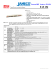
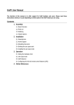
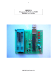
Friendly PIC Lab-I
PIC Microcontroller Development Board
Amer Iqbal Qureshi
User Manual
Microtronics Pakistan
Www.electronicspk.com
Friendly PIC Lab-I
Congratulations on purchasing our friendly PIC Lab-I development board. As the
name suggests this is not just a trainer board, but a complete development system.
The board is “friendly” in the sense that it does not bind your project to its configuration like many other boards do. This board is 100% configurable to user needs.
Powered with 18 pin PIC microcontrollers the board has a host of commonly required devices on it. Unlike many other boards these devices are not hard wired to
the I-O lines of microcontroller, giving you the ability to connect them to lines of
your choice.
Each device has its connections close to pre-selected I-O lines on which you just
place a jumper and they are connected. In case you want to connect the device line
to any other I-O just remove the jumper and use jumper cables to connect.
This has made the board configurable according to your choice. Just connect the devices required for the project and to whatever I-O lines you want and enjoy the project.
Board at a Glance:
Have a look at board and get comfortable with position of various devices. The
board has a host of commonly used devices with microcontroller
projects.
Power Supply
The board has to be given external power supply through a stable DC outlet. It has its own 5V regulator therefore the supplied
power can be anything from 6V to 12V. We prefer a 9V supply.
The 5V regulator tends to get hot when given more than 12V to
dissipate energy therefore it must be
properly heat sinked.
The center of power supply pin should be
positive, the board has a protection diode
to avoid reversed polarity feed to the circuit. An On-OFF switch has been provided to turn the power ON. An LED
close to power jack will show the power
status.
Microcontroller Socket
This board supports all 18-pin Microchip PIC microcontrollers. Most of the Microchip PIC microcontrollers are pin compatible, however there can
be an odd one with different layout.
The microcontroller does not need to be taken out
of the board in most cases as it can be programmed
right in the circuit. In case you need to take it out
and replace with another number if your project re-
quires a different one, then make sure it is inserted in correct direction.
We tend to supply the board with PIC16F819 microcontroller as it has built-in analog to digital converters as well that helps in acquiring external analog data.
Crystal Oscillator
An oscillator is the heart of any microcontroller application.
Most microcontrollers run with an external crystal oscillator
or another source. Some microcontrollers now have built-in
oscillators as well. Using those oscillators will reduce the
circuit and allow you to use the pins dedicated for crystal
connections as I-O lines.
Since this is a development board it allows you to experiment your project in any possible combination
you like. Notice there are two jumpers close to the
crystal oscillator. Placing these jumpers will connect
the oscillator to the OSC1 and OSC2 lines of the chip.
If you take these jumpers off the oscillator is disconnected and now you will have to enable the internal
oscillator using software commands. A Quick look at
the datasheet will reveal that (in case of 16F819) these
two lines are then available as RA6 and RA7 as general purpose digital I-O lines.
Note these are available on I-O headers of the board. Do not use these lines on
header if crystal oscillator is plugged in as these lines will have crystal signals then.
USART Serial Port
Although serial port is vanishing rapidly from PCs yet it is an important
device in the microcontroller world.
A large number of devices communicate between themselves using
UASRT protocols. A USART with
MAX232 level shifter has been provided on board for communication
with PC and other devices if required
by the project. The interface of the
USART device is an RX and TX line
indicated at a header close to the device. The RX pin will receive data
from microcontroller and send to the
host device (your PC for example)
The TX line will transmit data sent
by host device to your microcontroller. Opposite to these pins are pins
with labels B2 and B1. These are the
RB2 and RB1 lines from microcontroller. Microcontrollers with USART
module in them use RB2 to send data
(Tx) and RB1 to receive data (Rx).
Thus if jumpers are placed on these
lines the Rx of PC will get connected to Tx (RB2) of microcontroller and TX of PC
to RX of Microcontroller.
When jumpers are removed the pins are free and using jumper wires you can connect the Tx and Rx of Pc to any other lines of microcontroller and use Software
commands to produce serial data communication. Similarly in applications that do
not need serial communication, and you want to use RB2 and RB1 in your application, removing jumpers will free the I-O lines.
HD44780 Character LCD
Character LCD is most commonly used to display the results from microcontrollers.
HD44780 is the industry standard LCD type that is easy to use. Most of the popular
compilers provide pre-compiled libraries to communicate with this LCD type. A
header has been provided on this board to easily plug-in LCD when required. Also a jumper
header with LCD connections on one side and
recommended microcontroller connections on
other side has been provided. Placing the
jumpers will connect the LCD to these I-O
lines. In case your project requires these lines
and you want to relocate the LCD connections, just unplug the jumper or jumpers and
use jumper wires to connect the LCD lines to
I-O lines of your choice.
Most designs of LCD require a potentiometer
to set the contrast , we have permanently provided contrast through a 1.5K resistor. You
therefore can not set contrast of LCD in this
board. The value is optimum if your power is
5V with sufficient amperes to give the best
contrast. The backlight of LCD has been
given power directly so in this board backlight can not be controlled.
Note the same header block is also used to
connect IR sensor, which has no direct connection with LCD.
Push Switches
Push switches or momentary switches as they are generally called are also
commonly used to get user response or to simulate in a prototype the input from an
on-off type sensor.
Essentially you can
call push switch a
simple touch sensor.
There are three
switches on board
and their connections
are again provided
through jumpers to
RB7, RA2 and RA1.
just like any other
device if you want to relocate the connections unplug the jumpers and using jumper
wires connect to lines of your choice.
These switches are connected in Active Low configuration with a 10k pull up
resistor on active end. Thus the respective I-O line will see a logic 1 when switch is
open and logic 0 when it is pushed.
LED Indicators
LEDs are commonly used to indicate various status of the
application, like to indicate that monitoring of port is ON or
receiving of a signal etc. many development boards provide a
lot of LEDs, truly speaking the purpose is not an LED show
but to indicate a status. In any given project at the most one or
two status LEDs are used. However for learning purpose you
may need more to refine the programming skills.
Each LED is connected through a 220 to 330 ohms current
limiting resistor so that microcontroller pin does not get
damaged. The LEDs are connected through a header block to
RB0, RB3, RB4 and RB5.
Notice the placement of resistors and header block is not close
to the LEDs physically.
The anode of LEDs is connected to the I-O line and cathode is
permanently connected to ground. Thus a logic High on I-O
line will make the LED glow and a logic 0 will turn it Off.
Note that the default connections of LEDs to RB0, RB3,RB4 and RB5 are also used
by LCD module. Therefore if you want to use both devices in a project you will
need to redirect the connections to some other pins using jumper cables.
Heavy DC Load using TIP 122
Some applications may require driving a somewhat heavy DC load. This can be a
fan, DC motor, a solenoid or even a relay. We have provided a TIP 122 Darlington
pair for that. The TIP122 will take its
DC load directly from the one provided
by DC adapter. Although TIP122 can
easily tolerate currents up to 5A. We
suggest to remain within 1 to 1.5A as the
power will be supplied through 1N4007
diode which may not tolerate very heavy
current load.
The DC load is inserted into the T-Block
and the TIP122 can be controlled from
RB3 when jumper is connected. Notice
RB3 is also CCP1 which means hardware PWM module. So using PWM you
can increase or decrease the power de-
livered to DC load. Note a true PWM needs a properly setup low pass filter to give
analog output.
38 KHz Infra Red Remote Sensor
Most of the commonly used remote controls use 38KHz modulated infra red beams to send commands. This board has a standard sensor that can detect only 38KHz modulated signals and
will ignore all other type of IR signals.
The sensor by itself gives a logic low signal when the IR signals
are received and high when there is no signal. This is OK for remote control applications and indeed some compilers like PROTON Basic have built-in command to decode the Sony remote
controls.
However if you want to use it to communicate serial data using
an IR LED, then this becomes a problem as serial
modules when send logic high they expect the logic
high on other end. We have rectified this problem by
using a transistor inverter on the IR sensor output.
Thus our board will give a logic high when 38KHz
modulated signals are received and logic 0 when not.
If you combine it with a simple IR LED, that can be
easily plugged into I-O lines you can easily make IR
modem.
This arrangement however failed the SONY remote
command with PROTON Basic as it assumes a logic
low when there is signal. We have provided a complete
program to decode the Sony IR remotes at the end of
this manual, using this non-inverted arrangement.
The output of IR sensor can be connected to RA4
through jumper located on the LCD jumpers block.
Using jumper wires you can relocate the sensor output
to any other line of choice.
Analog Inputs
PIC microcontrollers vary in built-in Analog to digital converter modules. Some
controllers like 16F84 do not have ADC in them, while 16F628 has only comparator
modules, 16F819 has 5 channels of analog data. Details of these channels and the
pins are given in datasheets of the concerned controller.
Acquiring analog data can be a daunting task. First of all stray signals and sampling
line capacitance tend to change the data shape. Secondly analog data can be low
voltages or high. PIC ADC can handle voltages only up to 5V. Therefore smaller
volts are not a problem but a signal more than 5V can be problem. The standard
practice is to protect the I-O lines with a 5.1V zener diode and secondly to use a
voltage divider to scale down the incoming signals. For example if you want to work
with a 12V signal you will need to scale
it down 3 times to make it 4V and then
feed into the controller. We have provided two variable resistors (actually a
variable voltage divider) The input signal
first gets into the variable resistor and
from the center tape gets into PIC ADC
lines. Thus positioning the POT you can
scale down the signal volts.
The Input header has pin for analog signal as well as 5V and GND pins. This
will facilitate connecting the sensors or
devices that need 5V supply as well, otherwise use only signal and GND to acquire data.
If a jumper is placed on signal and VDD line the POT will get 5V analog signal and
you can experiment with ADC by rotating the POT to simulate various levels of 05V analog signals.
You can also use this arrangement to set the scale down position. For example you
want to work with 12V signal and want to scale it down 4 times. Thus making 12V
to 3V data. To adjust the pot position to achieve this just place a jumper between signal and VDD and measure the volts using a voltmeter at center pin or output pin of
the module. You have to get 4 times reduced 5V thus 5/4=1.25 adjust the pot in such
a way to get 1.25V at output. Now remove the jumper and you can safely give 12V
signal at input, the output will be reduced by 4 times that will be compensated for in
software by multiplying the value measured by 4.
There are two such modules and by default they can be connected to RA0 (which is
AN0) and RA3 (AN3).
Reference Volts
You can read about reference volts in the proper manual about analog data. I would
only mention that most projects do not need an external reference, as they use 5V
supply as reference. However PIC microcontrollers allow you to get external reference volts. RA3 or AN3 pin has this capability. That is why our second Analog module has by default connection to RA3. using software configuration you can set this
pin as analog channel, or act an ANref+ . In that case you can connect the signal sin
to 5V and set the pot to desirable levels.
For example your analog data is going to be in the range of 0 to 2.5V. So we want
the upper limit of ADC module to be 2.5V instead of 5V. This will be set by AN3 as
VRef+ and setting the output of second module to 2.5V using POT.
I-O Line Headers
Although the board contains a lot of devices that you can use to learn and explore
microcontrollers, but a real
project will need something
more than that. For example
you may need to have external memory in the form of
EEPROM, a real time clock or drive a set of motors. You will be using some devices
on board like LCD and
switches but want to interface
with your boards. This can be
done by connecting your project with this board through I-O
line headers. There are two
headers, one for PORTA and
other for PORTB. Each line is
labeled and each header has
GND and VDD supply in case
you board needs 5V supply
from this board. Note the VDD
header pin is directly connected
to the main VDD (5V supply of
the board). In case your external board has its own supply do not connect it to VDD of this board. Connecting
GND is OK (indeed required). This is to avoid an accidental higher volts to enter
this board and damage it.
Note PORTA headers have RA6 and RA7 as well, they are usually connected to oscillator and not used as I-O lines, however if you have disconnected the oscillator
and using internal oscillator then these lines are available as digital I-O. Similarly
the line labeled MCLR. This line can be configured as RA5 if MCLR function is
disabled using software settings. However note this pin has a 10K pull resistor on it.
In Circuit Serial Programming
The traditional method for programming microcontrollers was to insert the controller into a
specific device called programmer, transfer the
compiled .hex file into the controller and then
take the controller back into the development
board. This method requires removal of controller from the board again and again
that can damage the legs and is cumbersome.
The standard method today is to use In Circuit Programming. We have therefore provided a header called ICSP for that. In order to use this port for programming you
will need to read the guidelines from microchip about in circuit programming.
Your programmer must have the capability to program microchip microcontrollers in
circuit. If so then place a cable from programmer to this header and send programming commands. You will not need to take the controller out.
Microtronics PIC PG-II Programmer
A number of programmers exist in market to
transfer the .hex file into PIC microcontroller. We have developed this simple Serial
port based programmer. As you can see it
has In circuit programming header just like
the one on our board. Using a flat cable you
just connect this header with your board and
now you can program your controller.
Decoding SONY Remote Control using PROTON BASIC
compiler
'****************************************************************
' This program will decode the sony remote control without using SONYIN command
' The program just skips the header and gaps
' and counts the logic 1 and 0
' logic 0 is 250 us and logic 1 is 580 us
' so anything larger than 300 is logic 1 and otherwise logic 0
'*****************************************************************
Device=16F819
Xtal 20
All_Digital true
LCD_DTPin PORTB.4
LCD_RSPin PORTB.0
LCD_ENPin PORTB.3
Input PORTA.4
' logic 1 is 569
' logic 0 is 269
Dim x As Word
Dim a[12] As Word
Dim i As Byte
Dim c As Byte
Dim d As Byte
Cls
Print At 1,1,"Sony Remote"
While 1=1
'wait for the signal
While PORTA.4=0
Wend
' let header pass
While PORTA.4=1
Wend
GoSub gap
For i=0 To 11
x=0
While PORTA.4=1
Inc x
DelayUS 1
Wend
a[i]=x
GoSub gap
Next i
x=0
For i=0 To 11
x=x>>1
If a[i] > 300 Then
x.11=1
Else
x.11=0
EndIf
Next i
' from 12 bit data extract lower 7 bits that contain the command
c=x & %01111111
d= x >> 7
Print At 2,1, "key:",Dec2 c
Print At 2,10, "Dev:", Dec2 d
Wend
End
gap:
While PORTA.4=0
Wend
Return