1
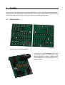
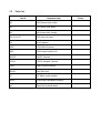
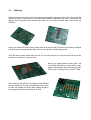
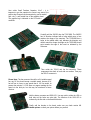
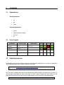
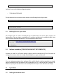
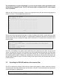
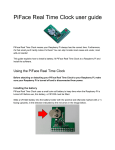
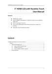
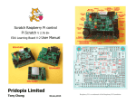
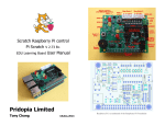
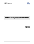
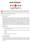
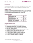
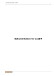
HotPi User Manual
The intention of this manual is to offer support for HotPi builders and users. Please read these
instructions entirely or in part depending on which parts of the HotPi board you are using.
Contents
1. Assembly
1.1. Board Overview
1.2. Parts List
1.3. Soldering
1.4. Header Options
2. Installation
2.1. Dependencies
2.2. Kernel Support
2.3. Rebuilding the kernel
2.4. Building the user space tools
2.5. Installing the user space tools
3. Operation
3.1. Setting the hardware clock
3.2. User space tools
3.3. HotPi-Daemon
3.4. Configuring the infra-red remote control features (LIRC)
4. Online References
1.
Assembly
If you've never soldered before then this is probably a good place to start, our boards are nicely manufactured
and well plated so the solder should run quite effectively. If you're new to soldering check the online references
at the end for a link to the “Soldering is Easy” comic which is an excellent beginners guide.
1.1
Board Overview
The HotPI Rev 2.1 PCB front and back.
A HotPi Rev 2.1 PCB and completed board. There
may be slight variations in the board that you have
received including for instance a different colour
PCB and silkscreen, or slight adjustments in the
component layout.
1.2
Parts List
Part ID
Component value
R1
100R (brown, black, brown)
R2
47R (yellow, violet, black)
R3
10K (brown, black, orange)
R4, R5, R6, R7
220R (red, red, brown)
C1
0.1uF capacitor
1838
TSOP1838 IR Receiver
RGB
RGB common cathode LED
2N2222
2N2222 Transistor
TIP122
TIP122 Darlington Transistor
FAN1
Molex 3 pin fan connector
DS1307
Real Time Clock
XT
32.768kHz crystal resonator
IROUT
3.5mm Stereo headphone connector
rpi
26pin male or female header
Picture
1.3
Soldering
Solder the resistors first, feed each of the resistors legs through the appropriate hole, I like to ensure that the
resistors all point the same way, in my case gold band towards the top edge of the board. I should note that
resistors aren't fussy about which direction they point, so if you make a mistake here it won't make any
difference.
Once you've inserted all of the resistors, solder them on the reverse side of the board, once a point is soldered
you should then trim any spare lead down so there's no stray bits of metal floating around.
You'll find that the solder moves quite fast and you only need a tiny bit of it when the pad and leg are hot
enough so be careful not to use too much.
Next up you should solder the clock crystal – this
is the small cylindrical bit of metal with two legs.
Again it doesn't matter which way around it goes.
It fits into the XT space just next to the RTC Chip.
Then solder the chip holder (or the chip if you feel confident
you wont damage it). The chip, and chip holder have a notch
on them, the notched side should point towards the gap in
the rectangle that represents the chip on the PCB.
Next solder Small Tantalum Capacitor, 0.1uF – it is
important to get the capacitor the correct way around, the
positive leg is longer than the negative leg, and is marked
with a tiny + and vertical line on the capacitor bead.
The negative leg is indicated on the PCB with a
small line.
Carefully add the 2N2222 then the TSOP1838. The 2N2222
has it's direction indicated with a bulge which more or less
matches the shape of the transistor. The TSOP1838 has a
bulge in the middle which only indicates the direction and
doesn't match the shape, the bulge on the TSOP1838 should
point towards the edge of the board as indicated by the
silkscreen.
Then solder the TIP122 and the fan connector. These
components face back to back with one another. Then pop
the IROUT connector in.
Please Note: The fan connected should be a 5V variable speed
fan, any DC fan should accept a variable speed, however a 5V
fan will run at closer to max speed than a 12V fan would. At
present the revision 2.1 PCB does not support reading the fan
speed via the third pin, but this may be introduced in future
versions.
Add the battery connector and RGB LED. You may wish to solder the LED on
both sides as the holes are quite tight. The direction of the RGB LED is
indicated by the flat side on the board and device.
Finally, add the headers to the board, make sure you check section 1.3
Header options to check your options before you proceed
1.3
Header options
There are two header options, the first option is to insert 13x2 pin female header pins on the bottom of the
board, in this case the board can be plugged directly into the raspberry-pi. The second option is to insert 13x2
pin male header pins on the top of the board, in this case a straight through 26 pin ribbon cable is required.
1.4
Assembling the IR Transmitter
The IR transmitter can be trained to transmit any Infra-Red remote control signal. However certain devices
such as a iRobot Roomba may have difficulties in correctly receiving and decoding the signals sent. This is a
problem more with the receiving devices than the transmitter itself. The common usage of the transmitter is to
control an external television or tuner device, for instance for controlling a cable TV set top box.
The HotPi is designed to be compatible with most IR transmitter jacks which come with media center remote
USB dongles or similar. Included in the kits is a length of wire approximately 40cm long and a 940nm IR LED.
This IR LED performs significantly better than the transmitters usually included with USB dongles.
WARNING: If you try to drive more than one LED at a time you will find that one or both of the LEDs will either
burn out, or the transistor will fail to deliver enough current to command an external device from any
reasonable distance. Especially if the LEDs are dissimilar.
To assemble the transmitter wire, connect the tip of the jack (centre solder tag) to the LED positive leg, and the
shield of the jack (outer most solder tag) to the LED negative leg. This is the same wiring pattern used in all IR
emitter leads like those which come with an MCE remote like the one depicted below.
2.
Installation
2.1
Dependencies
Build dependencies
•
git
•
gcc
•
make
Runtime dependencies
2.2
•
python
•
upstart (default on debian)
•
i2c-tools
•
lirc
Kernel support
Distribution
Kernel Version
Release Date
RGB RTC LIRC FAN
Raspbian
3.2.27
2012-12-16
YES
YES
NO
YES
Raspbmc
3.6.11
?
YES
NO
YES
YES
2.3
Rebuilding the kernel
To rebuild the kernel you should start by taking your existing system configuration i.e. one that you know works
and rebuilding using the latest raspberry-pi kernel source code.
$ git clone http://github.com/raspberrypi/linux.git kernel
$ cp /proc/config.gz ~/kernel/...
Next you need to configure the kernel for the features that we want to enable. The easiest way to do this is to
use the handy menuconfig tool which will present you with a kernel configuration utility usable with the
keyboard. Alternatively there's make gconfig or make xconfig but those will require extra dependencies.
$ cd kernel
$ make menuconfig
You'll need to set on the following configuration options
•
TODO MENU ITEM PATHS
For more advanced users those menu items translate to the following kernel config variables
CONFIG_... TODO CONFIG VARS
$ make install
$ make modules_install
2.4
Building the user space tools
The userspace tools are used for controlling the fan and LED behaviour as well as adding scripts for the
hardware clock. They are written in a combination of C and python and their code is available on github. Users
are encouraged to develop new features on top of the application code provided.
$ git clone http://github.com/klattimer/HotPi.git
$ cd HotPi
$ ./build.sh
$ ./install.sh
2.5
Software Installation (TODO PACKAGING NOT YET COMPLETE)
Download and install our HotPi debian package or binary tarball for controlling the LED and Fan speed and
setting up the hardware clock, this is simpler than building the user space tools yourself.
$ dpkg -i HotPi-1.0.deb
If you are missing any packages those packages will be available from the raspbian repositories so a simple
apt-get install will work fine, for instance we add a dependency on LIRC to ensure that will be available. The
binaries for picolor, pifan and their demons are statically linked to attempt to avoid difficulties with WiringPi.
3.
Operation
3.1
Setting the hardware clock
The information here is purely informational, if you are using our upstart scripts, the hardware clock
will have been configured for you. The RTC will save the time as acquired from NTP to the hardware
clock on shutdown.
Make sure the i2c device is accessible, in some of our experiments we found that the device may appear on
i2c bus 0 or i2c bus 1. The example below checks bus 1.
sudo modprobe i2c-bcm2708
sudo i2cdetect -y -a 1
0
1
2
3
4
5
6
7
8
9
a
b
c
d
e
f
00: -- -- -- -- -- -- -- -- -- -- -- -- -- -- -- -10: -- -- -- -- -- -- -- -- -- -- -- -- -- -- -- -20: -- -- -- -- -- -- -- -- -- -- -- -- -- -- -- -30: -- -- -- -- -- -- -- -- -- -- -- -- -- -- -- -40: -- -- -- -- -- -- -- -- -- -- -- -- -- -- -- -50: -- -- -- -- -- -- -- -- -- -- -- -- -- -- -- -60: -- -- -- -- -- -- -- -- 68 -- -- -- -- -- -- -70: -- -- -- -- -- -- -- -- -- -- -- -- -- -- -- --
We can see from the response here that there is a device on address 0x68, which is exactly where we expect
our clock to be. Now you've found the clock, it's a simple matter of making sure the time is set, and the clock
will keep that time for you as long as the battery works. Notice how i2c-1 is selected in the second line, this is
the bus number.
Sudo modprobe rtc-ds1307
sudo su -c "echo ds1307 0x68 > /sys/class/i2c-adapter/i2c-1/new_device"
sudo hwclock -r
sudo ntpdate -u pool.ntp.org
sudo hwclock —systohc
N.B. This is all handled in the upstart scripts hwclock.conf and hwclock-save.conf which can be found in
/etc/init - be aware that if the clock is not correctly set up it will not maintain an accurate time, and if the battery
were to expire while the raspberry-pi is turned off the time would be lost. The upstart scripts detect which bus
by identifying specific models of raspberry-pi, potentially your model may not be covered by this heuristic and
you may need to adapt the script. At the time of writing, these scripts worked with all models upto the latest.
(TODO rev8 IIRC)
3.3
Controlling the RGB LED and fan on the command line
The LED is configured in two parts, firstly there's the daemon which creates a socket to read from in /var/run,
the second part is the client, which lets you set the colour of the LED. In these instructions we assume your
system uses upstart i.e. debian based.
service picolor start
picolor /var/run/picolor \#450040
# To set the LED Color
You can make the change happen instantly by using the -i switch like so
picolor /var/run/picolor -i \#450040
Or you can set the speed of the change using the duration option
picolor /var/run/picolor -d 2 \#450040
Similarly for the fan
service pifand start
pifan /var/run/pifan -i [0 – 255]
# To set the fan speed
The system daemon should have been automatically configured to start with the system, the upstart script is
installed in /etc/init/hotpi should you have any problems
3.3
HotPi daemon (TODO UPDATE)
The system daemon will monitor the file '/sys/class/thermal/thermal_zone0/temp' for an if the temperature goes
above one of the trigger levels the appropriate speed is set. The trigger levels are set up in /etc/pifan.conf
# hotpi.conf
TRIGGER_LOW_TEMP=45
TRIGGER_LOW_SPEED=90
TRIGGER_MEDIUM_TEMP=60
TRIGGER_MEDIUM_SPEED=190
TRIGGER_HIGH_TEMP=80
TRIGGER_HIGH_SPEED=255
TEMP_FILE=/sys/class/thermal/thermal_zone0/temp
TEMP_MULTIPLIER=1000
FAN_SOCKET=/var/run/pifan
COLOR_SOCKET=/var/run/picolor
3.4
Configuring the remote control
The great thing about using the HotPi is that any and all standard remote controls are supported, we don't
include one in the kit because people can be choosy about something like their remote. The very best thing is
that if you've assembled the transmitter components you'll be able to control other devices via the raspberry-pi.
Setting up LIRC is easy, once you've installed the kernel either from our package or yourself, you should have
driver support configured, next up just make sure you have lirc installed and configure it correctly.
$ apt-get install lirc liblircclient0
Edit /etc/modules and add the following line, which will trigger udev to start lircd on boot
lirc-rpi
Once you're done with all that, you can activate the lirc device (for the first time) manually with
$ modprobe lirc-rpi
Please Note: Because udev names the lircd socket lircd-lirc0 in /var/run/lirc/ it causes a little difficulty with
some software as it is expected to be named differently – most LIRC aware software has a mechanism for
manually specifying the relevant socket.
Raspbmc has a neat solution to the naming issue in Raspbmc config, which allows you to enable GPIO serial
port receivers. This will activate the HotPi's infra red remote capability.
Before you start learning the codes for your remote, you should note that there is already a large archive of
supported remote controls which can be found here; http://lirc.sourceforge.net/remotes/ if your remote is not in
the archive we encourage you to send the configuration file to LIRC via their website/mailing list; http://lirc.org/
Adding a remote configuration can be done like so
$ sudo cat myremote.conf >> /etc/lirc/lircd.conf
If your remote is unsupported you will need to learn the remote codes, extensive documentation exists on
using lirc to capture remote codes, but put simply you can start by running
$ irrecord
# has step by step instructions for learning codes
Sending Remote Codes
$ irsend SEND_ONCE remote button # sends a signal once, SEND_START and SEND
STOP are used to repeat a button
It is possible to use lirc to do incredibly detailed and functional things with IR remote signals. For instance you
can execute programs on the system when a remote control is pressed, or you can control the mouse
movements using an infra red remote. It is even possible, using the lircrc configurations to set up behavioural
groups and states but these topics are outside of the range of this documentation.
4.
Online References
LIRC (Linux Infrared Remote Control)
•
•
http://lirc.org
http://aron.ws/projects/lirc_rpi/
Help with general raspberry-pi questions
Help with soldering
•
http://mightyohm.com/files/soldercomic/FullSolderComic_EN.pdf
Rebuilding kernel
•
http://elinux.org/RPi_Kernel_Compilation
HotPi Links
•
•
•
https://www.facebook.com/pages/Hotpi/573722212648718
http://thepihut.com/products/hotpi
http://www.kickstarter.com/projects/582604098/hotpi