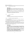
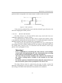
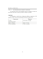
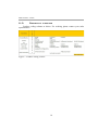
1
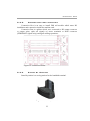
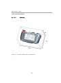
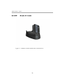
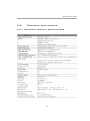
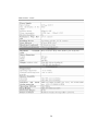
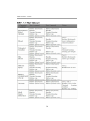
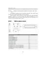
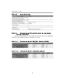
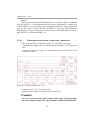
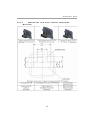
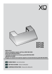
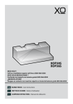
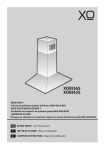
One H3 Series
0N3 H SERIES
H3
User Manual
Version 1.0 (Preliminary)
© 2012 0N3 Srl
All rights reserved
Contents
List Of Figures........................................................................................................6
Acronyms................................................................................................................1
General Information..............................................................................................3
1.1 Manual History..............................................................................................3
1.2 Manual organization......................................................................................3
1.3 Organization of safety notices.......................................................................3
1.4 Safety guidelines...........................................................................................4
1.4.1 Responsibilities......................................................................................4
1.4.2 Intended use..........................................................................................6
1.4.3 Protection against electrostatic discharges...........................................7
1.4.4 Transport and storage............................................................................7
1.4.5 Installation............................................................................................7
1.4.6 Operation main facts.............................................................................8
1.4.7 Supply voltage......................................................................................8
1.4.8 Emergency Stop push-button................................................................8
1.4.9 Enabling Device....................................................................................9
1.4.10 State Selector.....................................................................................11
1.4.11 Environmentally-friendly disposal.....................................................11
1.4.11.1.....................................................................................................12
Technical data.......................................................................................................13
2.1 Introduction.................................................................................................13
2.2 Selection guide............................................................................................15
2.3 Product coding.............................................................................................16
2.4 System overview.........................................................................................17
2.4.1 H3 terminal overview..........................................................................17
2.4.1.1 Ergonomics..................................................................................18
2.4.1.2 Housing .......................................................................................18
2.4.1.3 Operating and display field..........................................................18
2.4.1.4 Electronics....................................................................................18
2.4.1.5 Input devices...............................................................................19
2.4.1.5.1 Override potentiometers............................................................19
2.4.1.5.2 Handwheel (optional)................................................................19
2.4.1.5.3 Rubber keypad..........................................................................19
2.4.1.6 Interfaces to NC/PLC...................................................................20
2.4.1.7 USB interface...............................................................................20
2.4.1.8 Touch screen pen..........................................................................20
2.4.1.9 Safety related devices...................................................................21
2.4.2 Optional RFID TAG reader/writer.......................................................21
2.4.3 Connection box overview....................................................................23
2.4.4 Stand by Station...................................................................................23
4.5 Dimensions.............................................................................................24
2.4.5.1 Terminal.......................................................................................24
2.4.5.2 Connection Box............................................................................25
2.4.5.3 Stand by station............................................................................26
2.5 Technical data details...................................................................................27
2.5.1 Handheld terminal specifications........................................................27
2.5.1.1 Handheld terminal chemical resistance........................................29
2.5.1.1.1 Test results.................................................................................30
2.5.2 Cable connections................................................................................32
2.5.3 Cable connector specifications and pin-out.........................................34
2.5.3.1 DB25 connector pin-out...............................................................34
2.5.4 Safety-related devices..........................................................................35
2.5.4.1 Emergency Stop button................................................................35
2.5.4.2 Enabling device............................................................................35
2.5.4.3 State Selector................................................................................36
2.5.4.4 Details on the PL and SIL level of the safety related functions...36
2.5.4.4.1 Details on the PL (EN ISO 13849-1:2008)...............................36
2.5.4.4.2 Details on the SIL (EN62061:2005).........................................36
2.5.4.4.3 Parameters useful for the PL (EN ISO 13849-1:2008) and SIL
(EN 62061:2005) calculation...................................................................37
2.6 Connection box cabling scheme..................................................................38
2.6.1 Cabling: H3 to Connection Box..........................................................39
2.6.2 Cabling: Connection Box to CN/PLC.................................................41
2.7 Stand-by-station Mounting tips...................................................................42
2.7.1 Mounting the wall mount Stand-by Station.........................................43
2.7.2 Mounting the Desktop mount Stand-by Station..................................44
2.8 Standards ....................................................................................................45
2.8.1 EC Directives.......................................................................................45
2.8.2 International Safety Standards.............................................................45
List Of Figures
Acronyms
CNC: Computer Numerical Control
DC: Diagnostic Coverage
DLL: Dynamic-Link Library
ESD: Electrostatic Discharge
HMI: Human-Machine Interface
ISO: International Organization for Standardization
TFT: Thin Film Transistor
LCD: Liquid Crystal Display
MDI: Manual Data Input
MTTFd: Mean Time To dangerous Failure
OS: Operative System
PCB: Printed Circuit Board
PLC: Programmable Logic Controller
PLd: Performance Level Dangerous
PLr: Required Performance Level
SIL: Safety Integrity Level
PUR: Polyurethane
RGB: Red Green Blue
R/W: Read/Write
USB: Universal Serial Bus
VDC: Volts of Direct Current
XML: eXtensible Markup Language
PN: Part Number
SN: Serial Number
1
2
chapter
1
General Information
1.1
Manual History
1.2
Manual organization
This user manual is inteded to give all kind of information regarding H3
handheld terminal. Chapter 1 is dedicated to general information, operation and
safety main notices and an high level explanation of the device. Chapter 2 at first
gives an overview to each component and then gives the detailed technical data.
1.3
Organization of safety notices
All safety notices in this manual are specified as follows:
3
1.4
Safety guidelines
1.4.1
Responsibilities
H3 handheld terminal is a small, light and comfortable remote system
controller which, appositely configured and connected to a machine control logic
and safety, guarantees machine control and configuration and the implementation
of safety related functions.
All configuration and control commands selected through the keyboard or
the touch screen display, the optional handwheel and the potentiometers status are
sent to the machine control logic through a serial or ethernet communication
channel. H3 is available in two versions, depending on the desired communication
interface: ETHERNET or RS-422.
The safety related devices available on the H3 handheld terminal are:
Emergency Stop push-button, Enabling Device and State Selector.
All handheld terminal outputs: ETHERNET/RS-422 signals and the safety
related devices outputs, are cable connected to the machine control logic.
•
Danger!
User is responsible for the correct device installation and interfacing
to the machine control logic.
•
User is responsible for implementing the machine safety related
functions. H3 handheld terminal provides the best state of the art
technology safety devices. These allow to fulfill the best Performance
Level (PL) according to EN ISO 13849-1:2008 and Safety Integrity
Level (SIL) according to EN 62061:2005 (please refer to paragraph
2.5.4.4).
•
User should implement the safety related functions according to the
application safety level determined in a previous risk analysis.
•
User, during machine control logic implementation, is responsible for
considering all conditions related to the machine operations:
a) checking the Emergency Stop push-button, Enabling Device
and State Selector status;
b) checking all possible further safety devices available on
board of the machine: safety fences, optical barriers and so on.
4
General Information
•
User is responsible for considering all further safety and accident
prevention guidelines related to the particular working environment
in addition and independently from this document.
•
User is responsible for observing all safety precautions applying to
industrial control systems in accordance with national and
international regulations.
•
User is responsible for observing that all installation, commissioning
and maintenance tasks must be carried out only by qualified
personnel, so by persons who are familiar with transport, mounting,
installation, commissioning and operation of the product and who
have the appropriate qualifications. Furthermore it is suggested to
follow all national accident prevention guidelines.
•
All safety guidelines, cabling schemes, mechanical and electrical limit
values listed in the technical data must be read before installation and
commissioning and strictly respected.
•
User is not allowed to take care of the mainteinance and repair of the
safety devices on board of 0N3 H3 terminal. Each mainteinance and
repair operation must be remanded to 0N3 srl.
•
Information:
1.4.2
All instructions contained in this manual ensuring user safety must be
taken in consideration. Each non-conformity could cause the safety
functions integrated in the handheld terminal not to work properly.
Intended use
H3 handheld terminal has been designed, developed, and manufactured for
conventional use in industry. It was not designed, developed, and manufactured
for any use involving serious risks or hazards that could lead to death, injury,
serious physical damage, or loss of any kind without the implementation of
exceptionally stringent safety precautions. Such risks and hazards include the use
of H3 handheld terminal in the following applications:
•
•
•
•
nuclear reactions monitoring in nuclear power plants;
flight control systems;
flight safety;
mass transit control systems;
6
General Information
•
medical life support systems;
control of weapons systems.
•
1.4.3
Protection against electrostatic discharges
Electrical components that are vulnerable to electrostatic discharge (ESD)
must be handled accordingly.
•
Danger!
Do not touch the connector contacts;
Do not touch the contact tips when removing the protection covers.
•
1.4.4
Transport and storage
All kind of environmental (temperature, aggressive atmospheres, humidity)
and mechanical stresses over the accepted limits explained in 2.5 must be avoided
during transport and storage of the devices.
Two main considerations must be done in order to prevent damages during
transport:
•
Warning!
always use the original packaging;
always keep the right environmental conditions as explained in the
technical data.
•
1.4.5
Installation
Installation must take place according to the documentation and using
suitable equipment and tools.
•
•
•
Warning!
All devices must be installed by qualified personnel and without
voltage supplied
All national regulations about accident prevention must be taken into
account
Electrical installation must follow the fundamental guidelines (line
cross section, protective ground connection, the electrical limits
explained in the technical data etc.)
7
General Information
1.4.6
•
Warning!
Take care not to squeeze and thus damage the cable with any object.
Make sure that nobody can fall over the cable to avoid that the device
falls to grund.
Do not lay the cable over sharp edges to avoid damaging the cable
sheat.
Always operate the touch screen with the proper touch-pen. Never use
sharp objects that could damage the touch screen.
•
•
•
1.4.7
•
Operation main facts
Supply voltage
Caution!
The supply circuit must be protected using a 0.25A slow-blow fuse.
1.4.8
Emergency Stop push-button
The Emergency Stop push-button provides two redundant switching N.C.
(Normally Closed) contacts.
User should directly connect the Emergency Stop push-button outputs to the
machine cabinet and monitoring devices. For further information about the
handheld terminal cable pin-out please refer to paragraph 2.5.2.
The Emergency Stop push-button provided by H3 terminal allows the user
to fulfill high PL (according to EN ISO 13849-1:2008) and SIL (according to EN
62061:2005) for the related safety function once it is interfaced with the machine
control logic (please refer to paragraph 2.5.4.1).
•
•
•
Warning!
User is responsible for interfacing the Emergency Stop push-button to
the machine control logic and implementing the Emergency Stop
function according to the safety level determined in a previous risk
analysis.
User is responsible for interfacing the Emergency Stop push-button to
the machine control logic implementing the Emergency stop function
in category 0 or category 1 according to EN 60204:2006.
In case of drop or other possible damages of the device, the stop
function operation must always be checked by the operator.
8
General Information
•
Releasing the Emergency Stop push-button must never cause an
uncontrolled restart. User is responsible for implementing this
controls on the machine control logic.
The Emergency Stop push-button on the handheld terminal is not a
substitute for the Emergency Stop push-button located on the
machine.
For further and more detailed information about the Emergency Stop
push-button, as the electrical and mechanical life, please refer to
paragraph 2.4.1.9 and 2.5.4.1.
•
•
1.4.9
Enabling Device
The Enabling Device is a three positions enable switch providing two
redundant switching N.O. (Normally Open) contacts.
User should directly connect the Enabling Device outputs to the machine
cabinet and monitoring devices. For further information about the handheld
terminal cable pin-out please refer to paragraph 2.5.2.
Respecting the standard EN60204-1, two positions, “Null” and “Panic”,
represent off condition while only the “Enable” position allows activation.
The Enabling Device provided by H3 terminal allows the user to fulfil high
PL (according to EN ISO 13849-1:2008) and SIL (according to EN 62061:2005)
for the related safety function once it is interfaced with the machine control logic
(please refer to paragraph 2.5.4.2).
•
•
•
•
•
Warning!
User is responsible for interfacing the Enabling Device to the machine
control logic and implementing the enabling function according to the
safety level determined in a previous risk analysis.
The enable switch fulfils its protective function only if the operator
can recognize the danger in time.
In case of dangerous states the logic controller must provide that,
additionally to the enable switch, another conscious start command
should be required to allow activation.
The only person permitted in the dangerous area is the person
activating the enable switch.
For further and more detailed information about the enable switch, as
the electrical and mechanical life, please refer to paragraph 2.4.1.9
and 2.5.4.2.
Functionality
9
General Information
The Enabling Device can have three different positions:
The positions null and panic must be cabled and controlled by the machine
logic in order to guarantee a stop category 0 or 1 according to EN 60204:2006.
Zero position
When not pressed the Enabling Device returns to the zero position
Figure 1: Zero position
Enable position
When pressed the Enabling Device goes into the enabling position. This
condition is often associated to machine movement activation. When released it
goes back to the null position.
Figure 2: Enable position
Panic position
When the Enabling Device is pushed all the way in it goes to the panic
10
General Information
position which corresponds to the same contact condition as the zero state.
Figure 3: Panic position
If the switch is pushed all the way in and then released it goes directly to the
null state skipping the enable position.
1.4.10
State Selector
The State Selector is a 16 states BCD coded rotary switch with four nonredundant outputs and a common contact.
User should directly connect the State selector outputs and common contact
to the machine cabinet and monitoring devices. For further information about the
handheld terminal cable pin-out please refer to paragraph 2.5.2.
The State selector provided by H3 terminal allows the user to fulfil high PL
(according to EN ISO 13849-1:2008) and SIL (according to EN 62061:2005) for
the related safety function once it is interfaced with the machine control logic
(please refer to paragraph 2.5.4.3).
•
•
•
Warning!
User is responsible for interfacing the State selector to the machine
control logic and implementing the state selecting function according
to the safety level determined in a previous risk analysis.
The State Selector function should be only related to the selection of
the various working modes available on the machine by the logic
controller.
For further and more detailed information about the State Selector, as
the electrical life, plaese refer to paragrah 2.4.1.9 and 2.5.4.3.
The State Selector must be connected by the user in order to meet the
particular Performance Level (according to EN ISO13849-1:2008) or SIL Level
(according to EN 62061:2005) defined in the machine risk evaluation.
11
General Information
1.4.11
Environmentally-friendly disposal
All components related to H3 handheld terminal are designed to respect the
environment and reduce as much as possible its impact on pollution.
1.4.11.1
It is important to specify how to dismiss the different components of H3
terminal in order to have an environmentally-friendly recycling process.
12
Chapter
2
Technical data
2.1
Introduction
H3 handheld terminal is a small, light and robust mobile panel featuring a
powerful processor widely used in industrial products, a high reliability solid state
disc and a RAM memory bigger and faster than H2, a comfortable 5” TFT LCD
color touch display and a USB 2.0 port. The processor runs Windows CE 6.0
operating system. Customer has complete freedom of operation on the OS and can
build his own application, use third party software or run the available application
from 0N3. Emergency Stop push-button, Enabling Device and State Selector are
available on board. All configuration and control commands selected through the
keyboard or the touch screen display, the optional Handwheel and the
potentiometers status are sent to the machine control logic through an
ETHERNET or RS-422 serial communication channel. The data signals (RS422 /ETHERNET), the Emergency Stop push-button, Enabling Device and State
Selector outputs are cable connected to the machine control logic.
Figure 4: H3 handeld terminal
13
Technical data
A Connection Box and a Stand-by Station (SS) complete the system. The
Stand-by Station is a storing station for the handheld terminal. The Connection
Box is useful for a comfortable connection to the machine cabinet. For further
info please refer to 2.10 and 2.16. H3 also features an optional embedded RFID
TAG reader/writer for user or machine identification. For further information
please refer to 2.4.2
All of the components related to the H3 handheld terminal and the
interface to the machine control logic are hereunder schematically presented:
Figure 5: H3 system overview
14
Technical data
2.2
Selection guide
Figure 6: H3 handeld terminal selection guide
15
Technical data
2.3
Product coding
Product coding scheme as below. For ordering please contact your sales
representative.
Figure 7: Product coding scheme
16
Technical data
2.4
2.4.1
System overview
H3 terminal overview
H3 handheld terminal is hereunder in detail presented:
Figure 8: H3 handheld terminal overview
17
Technical data
2.4.1.1
•
•
•
•
•
Ergonomics
Functional hand grip, user configurable;
Comfortable and safe access to safety related devices;
Comfortable and secure handling using rubber membrane keyboard and
covering surface;
Comfortable handling, also using gloves, thanks to well-designed
command key spacing;
Clear display, user configurable brightness.
2.4.1.2
•
•
•
Housing
Vibration and shock resistant according to EN 60204/A1:2009 (par. 4.4.8),
EN 60068-2-6:2008 and EN 61131-2:2007 (par. 4.2.2).
Non-flammable material housing(fulfils UL 94-5VA), impact-resistant,
water-resistant IP 64, cleaning agents (alcohol and fabric conditioner), oils,
cutting oils (drilling oils), fat and lubricants resistant.
Extremely robust housing. Drop-tested according to EN 60068-2-31:2008.
2.4.1.3
•
•
•
Operating and display field
Rubber covered keys with mechanical pressure point.
2 LED's:
◦ RED color: indicates hardware failures;
◦ GREEN color: may be fixed or blinking and is controlled by OS;
Touch screen TFT LCD Display.
2.4.1.4 Electronics
•
CPU
•
•
•
•
•
•
600MHz ARM Cortex-A8 core;
16kB instruction Cache;
256kB L2 Cache;
Embedded Graphic engine;
Flash Memory: 128MB Flash NOR Solid State Disc (SSD);
RAM Memory: 128MB DDR2 SDRAM.
18
Technical data
2.4.1.5
Input devices
2.4.1.5.1
Override potentiometers
The two over-ride potentiometers can be used for different purposes, for
instance setting the spindle speed or the machine movement speed along a certain
axis.
•
Resolution: 0-255 linear
2.4.1.5.2
Handwheel (optional)
The handwheel is an optional accessory. It can be used for the machine
movement fine tuning in the “handwheel incremental JOG” working mode.
The handwheel counts 40 detents per each 360◦ turn. Clockwise turns
decrement while counter-clockwise turns increment the counter.
2.4.1.5.3
Rubber keypad
The mobile panel has a rubber keypad containing 19 keys. 6 keys
command keys, useful for a direct machine control. The remaining 13 keys
function keys, useful for navigating and operating through the panels of
software application. The letter or the symbol printed on the keys reminds
function.
Figure 9: Keypad
19
are
are
the
the
Technical data
2.4.1.6
Interfaces to NC/PLC
H3 is available in two versions according to the desired communication
interface:
•
RS-422: Full-duplx seil interface; bitrate is user configurable.
•
ETHERNET: 100 Mbps Fast Ethernet
•
fulfils standards: IEEE 802.3, IEEE 802.3u 100BASE-TX
•
supports auto cross-over (AUTO-MDI) function.
2.4.1.7
•
•
•
USB interface
USB 2.0 HOST interface
USB type-A connector
max 500mA output current
2.4.1.8
Touch screen pen
The touch screen pen is easily accessible in the back, on the right side of the
terminal.
20
Technical data
Figure 10: Touch screen pen
2.4.1.9
Safety related devices
Hereunder is shown the detail for the safety related devices position:
Figure 11: Safety related devices position
For all the information about the safety related devices and functions please
refer to paragraphs 1.4.8, 1.4.9, 1.4.10 and 2.5.4.
2.4.2
Optional RFID TAG reader/writer
H3 terminal features an optional embedded RFID TAG reader/writer.
Possible RFID TAG applications are user identification or tool/machine
identification.
H3 with embedded RFID reader/writer gives the possibility of associating
different operating rights to different handheld terminal operators or, for instance,
21
Technical data
recognizing tools and machines and dynamically select the appropriate HMI.
For reading/writing the RFID TAG user should simply bring the TAG closer
than 1cm to the rear part of the handheld terminal, as shown in the following
picture:
Figure 12: RFID TAG reader/writer position
22
Technical data
2.4.3
Connection box overview
Connection Box is an easy to install DIN rail module which eases H3
installation and connection inside the machine rack.
Connection Box is a splitter which, once connected to H3 output connector
or output wires, splits all signals on screw terminals or RJ45 connector
(ETHERNET signals only) easing all cabling operations.
Figure 13: Connection board
2.4.4
Stand by Station
Stand-by station is a storing station for the handheld terminal.
Figure 14: Stand-by Station
23
Technical data
4.5 Dimensions
2.4.5.1
Terminal
Figure 15: Terminal (dimensions in millimeters)
24
Technical data
2.4.5.2
Connection Box
Figure 16: Connection Box (dimensions in millimeters)
25
Technical data
2.4.5.3
Stand by station
Figure 17: Stand-by-station (dimensions in millimeters)
26
Technical data
2.5
Technical data details
2.5.1 Handheld terminal specifications
27
Technical data
28
Technical data
2.5.1.1
Handheld terminal chemical resistance
Test 1 (Less strict)
The units under test (UUT) are placed in a closable plastic box (120 x 85 x
65 mm).
A ball of absorbent cotton appositely tinctured with solvent will be placed
above the UUT; to avoid early evaporation, a generic solid body will be put over
the ball or, in a more simply way, the closable plastic box will be closed.
After a 10 minutes wait, the eventual body and the ball of absorbent cotton
will be removed; the solvent that remains on the UUT will not be wiped off and
the box will be closed immediately afterwards for 24 hours.
The test will be performed at environmental temperature (about 20 ◦C).
Test 2 (Very strict)
The units under test (UUT) are fully and thoroughly wet by solvent, then
will be closed into a closable box (120 x 85 x 65 mm) for 24 h.
Approximately 5 ml solvent will be sprayed over the UUT. The box will be
closed and the UUT will remain in the closed box for at least 24 hours.
The test will be performed at environmental temperature (about 20 ◦C).
Touchscreen test procedure
The Touchscreen is placed into a closable plastic box (120 x 85 x 65 mm)
and a ball of absorbent cotton appositely tinctured with solvent will be placed
above it, then the box will be closed for 1 h.
The test will be performed at environmental temperature (about 20 ◦C).
29
Technical data
2.5.1.1.1 Test results
30
Technical data
Touchscreen test results
Test passed with the following solvents:
•
•
•
•
•
Unleaded Gasoline;
Denatured Ethyl Alcohol;
Diesel
Kluber CONSTANT OY 32;
Acetone.
31
Technical data
2.5.2
Cable connections
Ethernet version
Ethernet Tx+ (Shielded Twisted Pair)
White/Green
Ethernet Tx- (Shielded Twisted Pair)
Green
Ethernet Rx- (Shielded Twisted Pair)
Orange
Ethernet Rx+ (Shielded Twisted Pair)
White/Orange
State Selector Common
Red/Blu
State Selector Bit 0
Grey/Pink
State Selector Bit 1
Yellow/White
State Selector Bit 2
White/Green
State Selector Bit 3
Brown/Green
Enabling Device N.O. Contact 1
Yellow
Enabling Device N.O. Contact 1
Green
Enabling Device N.O. Contact 2
White
Enabling Device N.O. Contact 2
Brown
Power Supply GND
Blue
Power Supply 24V
Red
Stop Button N.C. Contact 1
Black
Stop Button N.C. Contact 1
Pink
Stop Button N.C. Contact 2
Purple
Stop Button N.C. Contact 2
Grey
32
Technical data
RS-422 Serial Version
Serial RS-422 Tx+
(Shielded Twisted Pair)
Yellow
Serial RS-422 Tx-
(Shielded Twisted Pair)
Green
Serial RS-422 Rx-
(Shielded Twisted Pair)
Pink
Serial RS-422 Rx+
(Shielded Twisted Pair)
Grey
State Selector Common
Yellow/Brown
State Selector Bit 0
Yellow/White
State Selector Bit 1
Grey/Brown
State Selector Bit 2
White/Green
State Selector Bit 3
Brown/Green
Enabling Device N.O. Contact 1
White/Orange
Enabling Device N.O. Contact 1
Grey/White
Enabling Device N.O. Contact 2
Red/Blu
Enabling Device N.O. Contact 2
Blu
Power Supply GND
Brown
Power Supply 24V
White
Stop Button N.C. Contact 1
Black
Stop Button N.C. Contact 1
Grey/Pink
Stop Button N.C. Contact 2
Purple
Stop Button N.C. Contact 2
Red
33
Technical data
2.5.3
Cable connector specifications and pinout
H3 handheld terminal cable will terminate optionally with a DB25 male
connector, with a circular male plug or with no connector.
Both the DB25 connector and the circular plug provide a metal backshell
internally connected to the cable external and internal shieldings and to the
handheld terminal Ground. This will let H3 terminal ground and shieldings to be
connected with the machine cabinet “earth”.
2.5.3.1
DB25 connector pin-out
Figure 18: DB25 male connector (dimensions in millimeters)
34
Technical data
2.5.4
Safety-related devices
2.5.4.1
Emergency Stop button
2.5.4.2
Enabling device
35
Technical data
2.5.4.3
State Selector
2.5.4.4
Details on the PL and SIL level of the safety
related functions
In the following tables we will detail PL and SIL values, the parameters
useful for their calculation and the assumptions we made.
2.5.4.4.1
Details on the PL (EN ISO 13849-1:2008)
2.5.4.4.2
Details on the SIL (EN62061:2005)
36
Technical data
2.5.4.4.3 Parameters useful for the PL (EN ISO 138491:2008) and SIL (EN 62061:2005) calculation
Note 1
The safety devices (Emergency Stop Push-button, Enebling Device, State
Selector) on board of H3 handheld terminal are directly hardware-connected to the
output connector pins. For this reason, the numerical values shown in 2.5.4.4.1
and 2.5.4.4.2 consider the highest performances of these devices if used in the
conditions described in 2.5.4.4.3. The numerical values of MTTFd, PFHd, SFF
and DC were obtained through the assumptions shown in 2.5.4.4.3 and are related
to each safety function frequency of use. The values for the overall safety
functions of the machine depend on how the output safety signals are managed
inside the machine controller.
37
Technical data
Note 2
The Stop Push-button and Enabling Device on board of H3 are compliant
with IEC60947-5-1. Considering that and referring to paragraph D.5.3 (table D.8)
of ISO 13849-2, it is not possible to relate dangerous failures to these components
and, so, the values of b10d, MTTFd and PFHd for the Stop Push-button and
Enabling Device does not have any relevance (from a mathematical point of view:
b10d, MTTFd = infinite and PFHd = 0).
2.6
•
•
Connection box cabling scheme
The Connection Box, as shown in picture 18, is divided in two parts:
Terminal Side (upper part): for interfacing H3 terminal to the Connection
Box;
Controller Side (lower part): for interfacing the Connection Box to the
machine NC/PLC.
Figure 19: Connection Box TOP view
Connectors J6, J7, J10, J11 are not used.
Connection Box features a 0.25A slow-blow fuse (F1).
•
Caution!
In case of F1 fuse break, please replace only with a 0.25A slow-blow
fuse (size 20mm x 5mm). Fuse type example: Littlefuse 0218.250HXP.
38
Technical data
2.6.1
Cabling: H3 to Connection Box
Open connection
User must connect cable wires to the terminal J1. For a correct cabling
please refer to the following table:
VERSION
RS-422
Wire Connection
Connection Box J1
Yellow
3
Green
4
Pink
5
Grey
6
Yellow/Brown
7
Yellow/White
8
Grey/Brown
9
White/Green
10
Brown/Green
11
White/Orange
12
Grey/White
13
Red/Blu
14
Blu
15
Brown
19
White
20
Black
22
Grey/Pink
23
Purple
24
Red
25
39
Technical data
VERSION
ETHERNET
Wire Connection
Connection Box J1
White/Green
3
Green
4
Orange
5
White/Orange
6
Red/Blu
7
Grey/Pink
8
Yellow/White
9
White/Green
10
Brown/Green
11
Yellow
12
Green
13
White
14
Brown
15
Blue
19
Red
20
Black
22
Pink
23
Purple
24
Grey
25
40
Technical data
Both external and internal cable shieldings (copper braids) should be
connected to J4 ”Shield” pin.
DB-25 termination
User must connect H3 DB-25 male connector to J14 female connector.
2.6.2
Cabling: Connection Box to CN/PLC
For a correct cabling please refer to the following table:
41
Technical data
2.7
Stand-by-station Mounting tips
Stand-by Station is available in wall mount and desktop mount version.
Each version is mountable on different target surfaces hereunder summarized:
* Target surface: through hole and wall thickness more than 5mm
42
Technical data
2.7.1
Mounting the wall mount Stand-by
Station
43
Technical data
2.7.2
Mounting the Desktop mount Stand-by
Station
44
Technical data
2.8
Standards
H3 handheld terminal has been designed in order to conform to the
following european directives and international standards:
2.8.1
EC Directives
2.8.2
International Safety Standards
45
Technical data
46