1
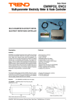
PRODUCT SAFETY SOLUTIONS
USER’S MANUAL
GLOW WIRE TESTER
MODEL
Serial No.:
GWT-200
35090/06
珠海科尔迈测试设备有限公司
ZHUHAI KEERMAI TESTING Co.LTD
TEL:0756-3353658 FAX:0756-3361895
www.keermai.com Email:[email protected]
珠海市吉大景园路16号华庆大厦三楼
PRODUCT SAFETY SOLUTIONS
GWT-200 MANUAL INDEX
Topic
Introduction
•
•
•
Page
3-4
Warnings
Before Using
Product Purpose
System Components
5
Product Specifications
6
•
•
•
•
•
Electrical
Environmental
Test Parameters
Fuses
Symbols/Labels
Installation Instructions
7-8
Operating Instructions
9 - 13
Maintenance
14
Parts/Service
14
Troubleshooting
15
Calibration
15
Reference Standards
16
Warranty
17
READ THE ENTIRE MANUAL BEFORE USING THE
GLOW WIRE TESTER
2
PRODUCT SAFETY SOLUTIONS
GWT-200
GLOW WIRE TESTER
IMPORTANT INSTRUCTIONS - - SAVE THESE INSTRUCTIONS
Introduction
Thank you for choosing the ED&D GWT-200 Glow Wire Tester. With proper use, care, and regular
calibration, it will provide many years of accurate and reliable service.
Upon receiving the unit please check for obvious physical damage to the packaging material and the
instrument itself. If any damage is evident please immediately notify your ED&D representative.
We strongly recommend you keep all ED&D packaging for future shipping requirements.
WARNING
WARNING: THE GLOW WIRE TEST INVOLVES A RISK OF FIRE!
YOU MUST PROPERLY PREPARE FOR CONDUCTING THIS TEST
THIS TEST MUST BE ATTENDED AT ALL TIMES
BEFORE USING:
1) DANGER: The Glow Wire operates at very high temperature (≈ 1000°C). Extreme caution should
be observed when using the GWT-200 = especially when attaching or removing the test samples.
2) DANGER: RISK OF HAZARDOUS ENERGY: The electrical connections to the glow wire operate at
low voltage/high energy. DO NOT wear jewelry when operating the GWT-200. DO NOT bridge the
glow wire connections (support rods) with any metallic object!
3) POTENTIAL FOR FIRE, EXPLOSION & FUMES: The Glow Wire Test can ignite your test sample.
Fumes from burning of test samples can be toxic. You must be prepared for these results by
conducting this test in the proper fire test environment = be sure to operate the Glow Wire Tester in
an area that protects the operator from toxic fumes/residues and provides for removal of any smoke
and fumes after the test = flame hood or other structure intended to contain flame and exhaust
fumes (use the Glow Wire Tester inside a suitable Fume/Flame Hood – available separately from
ED&D).
4) ATTENDED USE: Because of the risk of “fire” with the test sample, the GWT-200 is intended to be
attended at all times during use.
5) USE PROPER SAFETY PRECAUTIONS when using the Glow Wire Tester = properly protected
test area, CO2 fire extinguisher or other suitable fire protection/prevention equipment, wear safety
glasses, properly rated respirator if needed for fumes, maintain a clean work area with no exposed
hazards in the area, etc. It is your responsibility to insure a safe test environment.
6) CAUTION: The Glow Wire Tester is VERY heavy (72 lb. ≈ 33 Kg). Two people are required to
remove the Glow Wire Tester from the crate. Be sure to use proper lifting techniques.
3
PRODUCT SAFETY SOLUTIONS
PRODUCT PURPOSE:
The Glow Wire Tester model GWT-200 is designed to carry out fire hazard testing on solid insulating
materials and other solid combustible materials. This test is intended to determine the potential for the
test material to be ignited by an external heat source = simulates heating of combustible materials used
in products should they be subjected to high heat from adjacent parts (such as glowing elements,
overloaded resistors, hot coils and windings, etc.).
For the glow wire test, a loop of resistance wire is electrically heated to a specific temperature and the
specimen being tested is brought into contact with this heated wire for 30 seconds. The amount of force
between the glow wire and the test sample is held constant at 1 N. Observations and measurements
are made to evaluate the fire hazard presented by the test sample while exposed to elevated
temperatures.
The objective of the test is to record the behavior of the material when subjected to the high
temperature glow wire = time to ignition, time to extinguish, maximum flame height, and whether
dripping particles ignited the tissue paper. The test temperature and resulting behavior of the material
are used to identify the suitability of the material for specific application – it can also be used to develop
a flame rating for the material.
This product complies with IEC60695-2-10:2001 and other standards requiring Glow Wire Tests. See
page 16 for more details.
4
PRODUCT SAFETY SOLUTIONS
System Components - Control Panel:
A. Temperature Meter – displays glow wire temperature
B. Mains Indicator Light (Green) – illuminates when mains switch is “on”
C. Current Control Knob – to increase/decrease test current through the glow wire
D. Mains Fuse – see page 6 for ratings
E. Circuit Breaker – manual reset – push to reset
F. Mains On/Off Switch (0/I) – controls mains power to the unit
G. Current Meter (Ammeter) – displays test current through glow wire
H. WIRE OFF Switch (Red) – push to stop test current through the glow wire
I.
WIRE ON Switch (Green) – push to start test current through the glow wire
J. Control Fuse - see page 6 for ratings
K. Tissue Paper/Wood Surface – one package of tissue paper and one 10 mm thick wood board included
L. Bubble Level – for use in leveling the GWT-200
M. Sample Platform – includes brackets to hold test sample
N. Depth Limiting Spacer/Stop – limits penetration depth of glow wire into test sample to 7 mm
O. Glow Wire/Thermocouple – thermocouple measures temperature at inside tip of glow wire
P. Flame Height Gauge – allows for measuring the flame height when ignition occurs
Q. WIRE ON Indicator Light (Amber) – illuminates when test current is “on”
Q
P
O
A
B
C
N
D
E
F
G
H
I
J
K
5
L
M
PRODUCT SAFETY SOLUTIONS
PRODUCT SPECIFICATIONS: ± 2 % unless otherwise indicated
Mains Electrical Ratings:
120 or 230 VAC (± 10%), 50 – 60 Hz, 5.0/2.5 A
Mains Electrical Configuration:
Power Connection:
Environmental Ratings:
Overall Dimensions:
Overall Weight:
2 Wire + Ground (Earth)
Detachable power supply cord with integral plug
10 – 40 °C, indoor use only
12 in. D x 35 in. W x 25 in. H (30.5 x 88.9 x 63.5 cm)
72 lbs. (32.6 Kg)
Glow Wire Element:
Contact Force:
Glow Wire Penetration:
Wooden Board:
Distance to Board:
Tissue Paper:
see diagram on page 16
1 N (± 0.2N) between the test sample and the glow wire
7 mm (± 0.5 mm)
Approx. 10 mm thick
200 mm (± 5 mm)
ED&D model ATP-01 = weighs 12 g/m2 - 30 g/m2
Ammeter:
Temperature Meter:
Thermocouple:
0 - 200 A (± 2% FS)
0 – 999 °C (± 1% FS)
Type K, 0.5 mm diameter
(see markings on GWT-200 for voltage/current rating of your GWT-200)
Fuse
Mains
Fuse Rating for Units
rated 110 - 120 VAC
T5A, 250 VAC
Fuse Rating for Units
rated 220 – 240 VAC
T3A, 250 VAC
Control
T1A, 250 VAC
T1A, 250 VAC
Symbols/Location:
DANGER - SHOCK HAZARD POTENTIAL
• Electrical Enclosure Panels = for Qualified Service Personnel access
•
only.
DO NOT bridge the glow wire connections (support rods) = Risk of
Hazardous Energy (3 V, 200 A).
WARNING – READ MANUAL BEFORE USING
•
Enclosure Panels = for Qualified Service Personnel access only.
FUSE REPLACEMENT: Fuseholders located on front panel
•
See fuse ratings in table above. For continued protection against shock
& fire, replace only with the same type & rating of fuse. Use only UL,
CSA, BSI, or VDE certified fuses.
6
PRODUCT SAFETY SOLUTIONS
INSTALLATION INSTRUCTIONS:
1) Remove from Crate: CAUTION: The Glow Wire Tester is VERY heavy (72 lb. ≈ 33 Kg). Two people
are required to remove the Glow Wire Tester from the crate. Be sure to use proper lifting
techniques. Use care when removing the flame height gauge/ruler.
2) Product Support: This product is intended to be used within a fume/flame hood, on a tabletop
capable of safely supporting the weight of the unit (72 lb. ≈ 33 Kg). The standard specifies
conducting the Glow Wire Test in a draft-free chamber with a minimum 0.5 m3 volume.
3) Install Feet: Install each of the adjustable height feet into the integral studs on the bottom of the
unit.
4) Leveling: IMPORTANT: To insure the correct force is applied to the test sample, it is essential that
the GWT-200 is level when used. A bubble level is installed on the unit base to use in leveling.
Adjust the height of each foot until level and tighten the position nut after adjustment.
Use bubble level when
leveling the GWT-200
Install and adjust foot
height to level the unit
5) Release the Sample Carriage: Cut tie-wraps to release the sample carriage.
6) Verify Sample Carriage Operation: Verify that the carriage assembly is rolling smoothly. If the
assembly is not rolling or not rolling smoothly, verify that the tensioning cord to the weight is
properly seated in the pulley and not tangled with the carriage assembly.
• If difficulties persist, remove the rear carriage cover to access the roller system. Replace the
cover after correcting the problem.
Tensioning cord
should sit in groove
in pulley
Carriage
assembly
should roll
smoothly
in/out
Tensioning cord
should be a straight
connection
Remove right side
cover to correct any
movement problems
7
PRODUCT SAFETY SOLUTIONS
INSTALLATION INSTRUCTIONS: Continued
7) Install Flame Height Gauge: Install the flame height gauge (ruler on post). The gauge is to be
rotated such that the entire length of the ruler is facing forward = entire length visible while
operating the GWT-200. This gauge is used to measure the flame height during testing.
• DO NOT attempt to adjust the height of the ruler on the mounting bracket. The zero position
of the ruler is set to coincide with the top/front of the glow wire.
• You can adjust how close the ruler is to the glow wire by changing the mounting position of
the ruler bracket.
Position of support post can be
changed to move the gauge
closer/farther to the glow wire
8) Main Electrical Connection: Connect the Glow Wire Tester to a properly rated electrical source
using the integral power cord
• Be sure to observe all regulations contained in your local electrical code.
• Verify that the source voltage is rated to match the unit rating plate.
• Verify that the input plug is the proper plug configuration. If you need to change the plug,
please utilize a licensed electrician knowledgeable with your local electrical codes. Use only a
Safety Certified plug. The inlet coupler is a type CEE 22, rated 10 Amps.
8
PRODUCT SAFETY SOLUTIONS
OPERATING INSTRUCTIONS: Be sure to consider the instructions in your Safety Standard
ATTENDED USE
Because of the risk of “fire” with the test sample,
the Glow Wire Tester is intended to be attended at all times during use.
The operator must be prepared to measure the flame height
and further monitor the test to avoid flame propagation
Allow samples to self-extinguish per the test requirements
1) Prepare Test Samples: Prepare your test samples (and conduct any pre-conditioning) per the
requirements in your test standard (i.e. IEC60695-2-11, IEC60695-2-12, IEC60695-2-13)
• WARNING: Do not use samples larger than necessary to minimize the potential for
spreading of fire.
2) Mains Switch OFF: Turn the main switch to the “off” position.
3) Turn Current Control to Zero: Rotate the current control knob to the zero position = rotate
counterclockwise.
Rotate Current Control
Knob to zero =
turn counterclockwise
4) Retract Carriage Assembly: Pull the carriage assembly all the way back (away from the glow wire)
and use the locking bar to hold the assembly in the retracted position.
Pull here to retract
Flip “up” locking bar to
hold carriage
assembly in the
retracted position
9
PRODUCT SAFETY SOLUTIONS
OPERATING INSTRUCTIONS: Continued
5) Attach Test Samples: Loosen the sample securement brackets and slide the test sample between
them = tighten the brackets with the sample in position.
• NOTE: Additional holes are provided in the backing plate to allow you to move the bracket
position and adjust the spacing between the brackets. The backing plate is also adjustable.
• IMPORTANT: The test sample should be positioned in the center of the sample platform.
• IMPORTANT: The brackets must be spaced away from the backing plate by at least 9 mm
to insure that the glow wire has room to penetrate the test sample without contacting the
backing plate. Spacer bolts (between brackets & backing plate) have been provided to
insure this spacing = do not remove the spacer bolts.
Brackets
6) Adjust Stop: To set the 7 mm penetration depth limit:
a) Loosen the set screw in the adjustable stop,
b) Move the carriage assembly forward until the sample is touching the glow wire,
c) Slide the 7mm spacer and the stop forward until spacer is in contact with the stop bracket,
d) Tighten the set screw in the stop = this sets the maximum wire penetration depth at 7 mm as
required by the standard.
Sample in
contact with
glow wire
Spacer is against
stop bracket,
Adjustable stop is
against spacer
7) Remove Spacer: After you have tighten the set-screw in the stop, pull the carriage assembly back
as far as it will go = this will allow enough distance at the end of the stop rod for you to slide off the
spacer. After removing spacer, use the locking bar to hold the carriage assembly in the retracted
position. Store the spacer in a safe place.
Remove spacer from
end of stop rod
10
PRODUCT SAFETY SOLUTIONS
OPERATING INSTRUCTIONS: Continued
8) Set Flame Gauge: Install and rotate the flame gauge such that the entire length of the ruler is facing
forward = entire length visible while operating the GWT-200. This gauge is used to measure the
flame height during testing. See installation instructions if you wish to further adjust the position of
the ruler with respect to the glow wire.
• DO NOT attempt to adjust the height of the ruler on the mounting bracket. The zero position
of the ruler must coincide with the top/front of the glow wire to allow you to measure the
flame height.
• You can adjust how close the ruler is to the glow wire by changing the mounting position of
the ruler bracket.
Position of
support post can
be changed to
move the gauge
closer/farther to
the glow wire
Zero on ruler
aligns with top
edge of glow
wire
9) Withdraw Sample: Pull the carriage assembly all the way back (away from the glow wire) and use
the locking bar to hold the assembly in the retracted position.
Use locking bar to
keep carriage
assembly retracted
10) Prepare Tissue Paper/Board:
• Wrap the wood board (approx. 10 mm thick) with 1 layer of tissue paper (ED&D model # ATP01 or equivalent) and secure tissue paper by tape under the board.
• Place the board under the glow wire – be sure board/tissue paper is under the area where the
glow wire will contact the test sample.
• IMPORTANT: Only use tissue paper which has not been previously burnt or discolored. Use
new tissue paper any time dripping/flaming particles have touched the tissue paper.
Notch in board aligns with
support post for flame gauge
Space between glow wire
support posts and board
Wrap board with tissue
paper and tape under board
11
PRODUCT SAFETY SOLUTIONS
OPERATING INSTRUCTIONS: Continued
DANGER – BURN HAZARD
The Glow Wire operates at very high temperature (can exceed 1000°C).
Extreme caution should be observed when using the GWT-200.
ALWAYS ALLOW THE GLOW WIRE TO COOL TO ROOM
TEMPERATURE BEFORE CONTACTING THE TEST SAMPLE
11) Set Temperature:
a) Current Control Knob should be in the zero position = rotate counterclockwise,
b) Turn “on” the mains switch = mains indicator light will illuminate green and the temperature
meter will operate,
c) Press the green WIRE ON switch = WIRE ON light will illuminate amber,
d) Rotate the current control knob clockwise to the position that results in the specified test
temperature. See the chart below for typical test temperatures and the approximate test
current for each.
• Turn the knob to the appropriate test current using the ammeter for reference.
• After glow wire fully warms, make additional adjustments using the knob until the
temperature meters shows your desired test temperature.
• IMPORTANT: Allow temperature to stabilize for 60 seconds before proceeding.
Mains Indicator
WIRE ON Indicator
Current Control Knob
WIRE ON Switch
Mains On/Off Switch
WIRE OFF Switch
Test Temperature
Approximate Wire Current
550 °C
50 Amps
650 °C
75 Amps
750 °C
90 Amps
850 °C
105 Amps
960 °C
125 Amps
See your test standard for test temperature tolerance;
Typical tolerance is ± 10K
12
PRODUCT SAFETY SOLUTIONS
OPERATING INSTRUCTIONS: Continued
12) Move Sample to Glow Wire:
a) While holding the carriage assembly, move the locking bar to release the assembly,
b) Guide the carriage assembly forward = as the sample approaches the glow wire, release the
carriage assembly allowing the sample to come in contact with the glow wire = the carriage
assembly will maintain a 1 N force between the sample and the glow wire,
• IMPORTANT: Per the standard – DO NOT adjust the test current/temperature after
the glow wire contacts the test sample.
c) During testing, using a stop watch or other suitable timing device to record:
• The start time = when the glow wire and test sample initiate contact,
• The time elapsed to ignition,
• The time for an ignited sample to extinguish after removal of the glow wire,
• The maximum flame height = see your test standard for further details,
• Any ignition of the tissue paper (any charring, burning, discoloring, etc.).
13) Withdraw the Test Sample: After the test time of 30 sec. ± 1 sec, slowly retract the sample platform
assembly and lock into the retracted position using the locking bar.
14) Turn Off Glow Wire: Press the red WIRE OFF Switch = the WIRE indicator light will extinguish. The
ammeter should immediately go to zero. The temperature meter will continue to display the glow
wire temperature.
• DANGER: Extreme burn hazard. Although the wire current is off, it will take several minutes
for the glow wire to cool. Allow the glow wire to cool to room temperature before proceeding.
15) Remove Sample: AFTER THE GLOW WIRE HAS COOLED TO ROOM TEMPERATURE, remove
the test sample.
16) Repeating Test: AFTER THE GLOW WIRE HAS COOLED TO ROOM TEMPERATURE if you will
be conducting another test, return to step 2.
17) Test Conclusion: At the conclusion of testing:
• Turn the current control knob to the zero position = rotate counterclockwise
• Turn the Mains switch “off”
• Clean glow wire = with a non-abrasive cloth or brush = do not alter the glow wire shape/size.
• Protect the GWT-200 from dust, dirt, and other contamination when not in use = especially
important to keep the rods/rollers that are part of the moving carriage assembly from
contamination.
13
PRODUCT SAFETY SOLUTIONS
MAINTENANCE: Replacement of the glow wire and thermocouple are to be conducted by
Qualified Service Personnel Only.
A) Overall Unit:
• WARNING: Do not leave the GWT-200 with the element energized for long periods of time.
Warm up the unit, allow temperature to stabilize, conduct the calibration, and then shut the
unit off.
B) Glow Wire:
• After Each Use: Insure that the glow wire is clean of any residue. DO NOT use any abrasive
objects on the glow wire = using abrasive objects will change their shape and may necessitate
replacement. Do not use tools to scrape off residue, and do not use abrasive cleaners or
materials on the glow wires. The glow wire is very expensive to replace due to the precision
dimensions and low tolerance.
• Periodically measure the tip diameter of the glow wire. WARNING: Only measure the glow
wire when the glow wire has cooled to room temperature. Per the requirements in the
standard, the glow wire should be replaced when the diameter has been reduced by 10% from
its original bent diameter (must measure glow wire when new).
• Contact ED&D for replacement glow wires = ED&D model P-GWT-200-E.
C) Thermocouple:
• Due to the extremely high test temperatures, the thermocouple will occasionally need to be
replaced. For this reason, you may wish to retain an extra thermocouple so you are prepared
when the thermocouple burns open.
• Insure that the thermocouple is inserted fully into the hole in the back of the glow wire tip. The
thermocouple is intended to be in contact with the inside surface of the glow wire tip. The
thermocouple can be gently bent to reposition as needed.
• Contact ED&D for replacement thermocouples = ED&D model P-GWT-200-T.
D) Carriage Assembly Rods/Rollers:
• Be sure that the rods remain free of contamination. Use a soft cloth to wipe the rollers clean
as needed. Any contamination of the rods can affect the force applied to the test sample. DO
NOT lubricate the rods as this will only attract contamination. The brass rollers within the
carriage assembly housing can be lubricated with light machine oil.
PARTS/SERVICE:
•
Contact ED&D for all parts/service.
o Replacement glow wire is ED&D model P-GWT-200-E.
o Replacement thermocouple is ED&D model P-GWT-200-T.
o Silver foil (min. 99.8% pure), approx. 0.06 mm thick, is ED&D model GWT-SVR.
o Tissue paper is ED&D model ATP-01.
14
PRODUCT SAFETY SOLUTIONS
TROUBLESHOOTING: WARNING: Risk of Shock! The electrical enclosure panels should be
removed by Qualified Service Personnel only.
1) Unit Is Not Operating – Mains Indicator Light Not Lighting:
•
•
•
Verify that the on/off Switch is “ON” (front panel).
Verify that the power cord is plugged in and your power source is turned “on” and operating
properly.
Disconnect power and verify that the main fuse is intact (front panel).
2) Unit Is Not Operating – Mains Indicator Light Is Lighting but Temperature Does Not Rise:
•
•
•
Verify that the Circuit Breaker is reset = push to reset.
Verify that you have pushed the WIRE ON switch to energize the glow wire.
Rotate the Current Control Knob in a clockwise direction to increase glow wire
current/temperature. The ammeter needle should rise shows the current increase.
o If the current does not rise when turning the control knob, disconnect power and
verify that the control fuse is intact (front panel).
o If the current does rise when turning the control knob, push the WIRE OFF switch.
Allow the glow wire to cool to room temperature. Then verify that the thermocouple is
properly inserted into the hole on the back of the glow wire. If the thermocouple is
properly inserted, the thermocouple may need to be replaced – conduct silver foil
melt calibration process.
3) Temperature Rise Inconsistent:
o
o
o
Perform silver foil melt calibration process to insure proper temperature display.
Verify glow wire – see calibration instructions. Replace as needed.
Replace thermocouple.
CALIBRATION: The Glow Wire Tester was completely calibrated prior to shipment by ED&D and a
certificate of calibration was included with the unit. NOTE – removal of the electrical enclosure panel is
to be done by Qualified Service Personnel Only. Re-calibration points are as follows:
• WARNING: Do not leave the GWT-200 with the element energized for long periods of time. Warm
up the unit, allow temperature to stabilize, conduct the calibration, and then shut the unit off.
• Glow Wire: The glow wire was calibrated to the dimensions shown in the diagram on page 16. You
will only need to measure the diameter of the glow wire tip periodically. = Note that the 4.0 wire
diameter specification is prior to bending. The glow wire tip diameter should be measured when
new = the standard specifies that when the glow wire tip diameter is reduced by 10% from its
original bent diameter, it should be replaced.
• Temperature Measurement: The temperature meter and the thermocouple should be annually
calibrated. NOTE – the silver melt calibration method described in the next item is the method of
calibration described in the standard.
• Silver Melt: Per the standard IEC60695-2-10, the system should also be calibrated to verify that a
strip of pure silver foil starts to melt on the upper surface of glow wire tip at 960 °C ± 15 °C.
o Silver foil, min. 99.8% pure, measuring approx. 2 mm2 x 0.06 mm thick, available from
ED&D = model GWT-SVR.
o Be sure that all silver foil is removed from the element after calibration.
• Ammeter: The ammeter is for reference only and is therefore not required to be calibrated.
• Force: If the system is level and the carriage assembly (weight, cord, rods, rollers) are not subject
to damage or contamination, the force should remain constant and not require re-calibration.
15
PRODUCT SAFETY SOLUTIONS
REFERENCE STANDARDS: This product complies with the International Standard for Fire Hazard
Testing – Glowing/hot-wire based test methods – Glow-wire apparatus and common test procedures,
IEC60695-2-10:2001. It is intended to be used by glow wire application standards IEC60695-2-11,
IEC60695-2-12, and IEC60695-2-13.
This product also complies with most end-product standards requiring Glow Wire Tester compliance such
as IEC60335-1, IEC60950-1 and other standards with the following Glow Wire Test specifications. Note
that a modified version of the GWT-200 is available for testing to UL746A = element penetration allowed to
15 mm; higher VA supply source.
Glow Wire Detail
Dimensions in mm
± 2% unless otherwise noted
Glow Wire Material:
Glow Wire Diameter:
Iron free, NiCr (80% Nickel, 20% Chromium)
4.0 mm ± 0.04 mm (before bending)
16
PRODUCT SAFETY SOLUTIONS
LIMITED WARRANTY
Educated Design & Development, Inc. (“ED&D”) hereby warrants to the original purchaser of any new ED&D Glow
Wire Tester that the device shall be free from defect in material and/or workmanship. This warranty shall extend for a
period of 1 year (365 days) from the date of purchase. Should any defect arise within the warranty period, ED&D may
repair the unit (at ED&D), send replacement parts, or replace the defective unit with a new unit at ED&D’s discretion.
Under no circumstances, however, shall ED&D be required to refund the purchase price of any Glow Wire Tester.
This warranty does not cover any failure or damage to the product resulting from accident, alteration or misuse of the
product or failure to follow manufacturer’s operating instructions. Furthermore, this warranty does not cover damage
caused by use of any attachment not original equipment of the product. ED&D shall not be liable for any damage
caused by use of the product other than indicated in the manufacturer’s instructions.
ED&D DISCLAIMS ANY LIABILITY FOR ANY DAMAGES RESULTING FROM DELAY OR LOSS OF USE AND
SERVICE, OR REPAIR, OR FOR LOSS OR DAMAGED DEVICES, OR FOR ANY INCIDENTAL OR
CONSEQUENTIAL NEGLIGENCE OR OTHER FAULT ON THE PART OF THE MANUFACTURER OR OTHERS.
THE IMPLIED WARRANTIES ON THIS PRODUCT SHALL BE IN EFFECT ONLY FOR THE DURATION OF THE
EXPRESSED WARRANTY PERIOD AS SET FORTH ABOVE, AND THEREAFTER, THERE SHALL BE NO
WARRANTIES, EITHER EXPRESSED OR IMPLIED, INCLUDING WARRANTIES OF MERCHANTABILITY OR
FITNESS FOR PARTICULAR PURPOSE ON AN ED&D GLOW WIRE TESTER.
珠海科尔迈测试设备有限公司
www.keermai.com Email:[email protected]
珠海市吉大景园路16号华庆大厦三楼
ZHUHAI KEERMAI TESTING Co.LTD
TEL:0756-3353658 FAX:0756-3361895
17