1
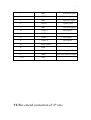
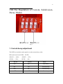
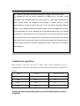
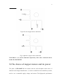
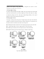
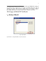
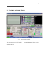
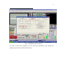
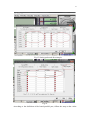
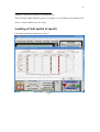
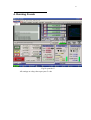
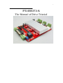
1 IFS-6560T3-N The Manual of Drive Triaxial 2 Content 1、Summary .................................................................................................. 错误!未定义书签。 2、The advantages of TB6560AHQ ............................................................... 错误!未定义书签。 2.1、In the low-speed operation system advantages ........................................................................ 3 2.2、In the high-speed operation of system advantages ................................................................... 4 3、The brief Performance of IFS-6560T3-N .......................................... 错误!未定义书签。 4、The General diagram of IFS-6560T3-N: ................................................ 错误!未定义书签。 5、The definition of each signal output pin parallel port: ........................... 错误!未定义书签。 6、The extended of 4th axis connection: ..................................................... 错误!未定义书签。 7、The connection of limit switch: ................................................................................................ 8 8、Current, breakdown, decay modes of regulation: ................................................................... 10 8.1、Current decay adjustment ....................................................................................................... 10 8.2、Subdivision regulation ........................................................................................................... 11 8.3、Current setting ........................................................................................................................ 12 9、Connected in a variety of stepper motor ................................................................................... 12 10、The choice of stepper motors and its power: ........................................................................ 13 11、Usage of MACH Software .................................................................................................... 15 11.1、Startup of Mach3 .......................................................................................................... 15 11.2、The basic settings of Mach3 ......................................................................................... 16 11.3、Setting of the limit switch mach3 ......................................................................................... 20 11.4、Running of Gcode ........................................................................................................ 21 12、Contact us ................................................................................................................................ 24 3 I.Summary The computer engraving machine is a new set of engraving and milling. The machine is mainly suitable for processing a variety of colorful patterns mould, such as,matrixes for embossing,sole mould,button mould,Zipper model,Stamping die design and die text,Instrument Mould,glass mold,etc.Also applies to advertising, such as, logo of firms,scutcheon,module,ofbuilding,badge,name-plate,panel,association's,emblem,door -plate,destination,board,decoration,upholster,etc. And applies for graphic engraving,Yin wen and Yang wen profile, and relief sculpture,such as portrait,scenery,Calligraphy Lettering,seal,etc. The company's 3-axis Engraving machine drive will composed minimum control system, using high-performance special micro-step control of TB6560 chip , open micro-computer control according to user requirements to functional design to the driver board.The control panel suitable for driving any small or four-phase or two-phase hybrid stepping motor. And have 4 files adjustable features of current 0.6A, 1.2A, 1.8A, 2.5A , support MACH2, MACH3 ,KCAM4Series software,Widely used in mold processing, graphic sculpture。As a result of new bipolar constant-current chopping technique, high precision, the motor running,with small vibration, low noise, smooth operation, safe and convenient, it is welcomed by the vast number of DIYers and engraving machine manufacturers. II.The advantages of TB6560AHQ 1、In the low-speed operation system advantages Low-speed operation system means clock frequency is not high, a small current drive based , such as several to 100 rpm, under the conditions of the user, in such applications will increase in costs such as using the traditional driver, either due to integrated chip subdivision is too low, leaving the low-speed vibration is too large; either had to choose a high drive segments. The advantages of TB6560AHQ low vibration and noise.Because the chip comes with an optional sub-2,4,16, enough to meet speed nearly a few to high speed. Less heat:Large enough to heat the chip comes with a separate support the cooling requirements of small current drive Supports a variety of stepper motor:Customers can choose slightly larger moment of a hybrid or permanent magnet stepper motor, the motor work in the allowed 4 peak torque between 30-50 percent, the motor costs almost the same; the chip set to provide more current file and current decay model, support various parameters under thethe same power index . 2、In the high-speed operation system advantages High-speed operation system means clock frequency is higher, and a large current drive-based. Such as speed close to thousand rpm, under this application,compare with traditional driven program,Either due to integrated chip segment is too low, leaving the system is too small speed range,Either due to excessive breakdown and increase high costs, may also caused by high torque decrease vibration and noise. The advantages of TB6560AHQ Low vibration and noise.As the chip TB6560AHQ comes with 16 segments, meeting nearly from a few to thousand rpm. and generates automatically a pure sine wave control current,compare with another highly integrated chip, the high torque at the same speed will not only not decreased, but increased..As TB6560AHQ can withstand the peak driving voltage 40V, 3.5A peak current, it provides continuous technical support.when the motor torque in a large, high-speed operation. .Supports a variety of stepper motor.Customers can choose a hybrid moment slightly larger or permanent magnet stepper motor, in the maximum torque of between 30-50%, the motorthe costs is almost the same. The chip provide high current set and multi-profile current decay mode, support the same power index of the various parameters under the stepper motor. Less heat.The embedded drive compact, easy to heat.When it drive in high current , the chip surface to facilitate the external cooling radiator, the user can also be directly connected to the metal shell of the original controller, In short, because TB6560AHQ is highly integrated, the external circuit is very simple, it is high reliability, and support 57 and some 86 per minute stepper motor from a few dozen to thousand rpm.in the wide speed application development and enable the both costs down of numerical control equipment and production 5 III.The brief performance of TB6560T3V1 We have accumulated many years of design experience in 3-axis engraving machine drive. And developed this type of TB6560T3V1. The following features: Three stepper motor drive can be run simultaneously With 4-axis expansion, if you need to extend it Spindle relay output, if you use the mach3 to control spindle start and stop Semi-flow control, when motor stop, current is reduced to the minimum The interface with the fans, you can add any fans With 3-way 0.8-3.5A (peak) adjustable current, rated output two-phase bipolar stepper motor driver Interface with Standard parallel port , support MACH2, KCAM4 series software With photoelectric isolation and DCDC power quarantine, and protect your PC parallel port and equipment Limit the interface with quadruple limit switches can be connected simultaneously Support the choice of four segments - 1,1 / 2,1 / 4,1 / 16 Stability,and small heat,24-36V single power supply input with switching power chip supply 5V power By RC +7414 automatic semi-flow, reducing motor heating, when motor the current decreases automatically. IV.The general diagram of TB6560T3V1 stops 6 Fig.1 V.The definition of each signal output pin parallel port Fig.2 25-pin parallel port control is defined as follows: DB25 PIN The role of the pin on notes driver board 1 EN Enable all axis 2 STEPX X pulse signal 7 3 DIRX X direction signal 4 STEPY Y pulse signal 5 DIRY Ydirection signal 6 STEPZ Z pulse signal 7 DIRZ Z direction signal 10 LIMIT-1 Limit input1 11 LIMIT-2 Limit input2 12 LIMIT-3 Limit input3 13 LIMIT-4 Limit input4 14 Relay control 15 blank 16 STEPB- B(4th axis)pulse signal 17 DIRB- B(4th axis)direction signal 18-25 GND VI.The extend connection of 4th axis 8 Fig.3 9 VII.Limit switch connection Fig.4 10 VIII.The Regulation of Current, Subdivision, Decay Modes Fig.5 1. Current decay adjustment The D1D2 are switches on the panel to set the current decay value DIP switch on of two D1D2:,D1/D2: ON/ON——100%; ON/OF——25%; OF/ON——50%; OF/OF——0%; DIP D1 DIP D2 Mode ON ON Fast decay OF ON 50%fast decay ON OF 25%fast decay OFF OFF Slow decay 11 Q: What are the specific role of the current decay of stepper motor driver board? A:Subdivision is now the current subdivision of stepping motor. The phase current according to the sinusoidal tangent the current point as a basic point subdivision.when phase current reaches the subdivision that through to control current to control decay.Otherwise, if angle overshoot will occur, can not be stuck in sub-angle。Different modes of decay depends on different in speed of motor. Fast decay at high speed, low decay at low speed,Slow decay occurs vibration, noise, when high-speed.In severe cases, will lead to position not allowed,when we select low speed motor to faster decay. Motor Control IC for the current decay of the H bridge is the control mode switch.The high side of the tube when the slow decay off, fast decay tube are closed when the high and low side.Mixed decay is the fast decay and then a slow decay, mixing ratio of decay and power for the chip also will be different. 2.Subdivision regulation DIP switches on the M1, M2 two to adjust, driver board subdivision may be adjustable,DIP switch The correspondence location and mode of between segments as follows: DIP M1 DIP M2 Subdivision mode ON ON 1/8 OFF ON 1/16 ON OFF 1/2 OFF OFF 1 To make the motor run smoothly, please try to choose high segments, such as 1 / 16 segments 12 3、Current setting Fig.6 Current regulation is by the panel to T1T2 two DIP switches to control .Figure XYZA current regulation identifies the location of the 2-way DIP switch Dip T1 Dip T2 Value of current ON ON 20%*2.5A OFF ON 50%*2.5A ON OFF 75%*2.5A OFF OFF 100%*2.5A Proposed stepper motor current as close as possible the rated current IX.Connected in a variety of stepper motor Motor connection diagram, please refer to Figure 1 Fig.7 Four-wire stepper motor connection 13 Fig 8 Six-wire stepper motor connection Fig 9 eight-wire stepper motor connection Notes:Motor A,-A, B,-B, connected respectively, four wires connected driver board AP, AM, BP, BM X.The choice of stepper motors and its power The panel of IFS-6560T3-N axis match with two and four-phase motor drive of domestic and foreign manufacturers , in order to obtain the most satisfactory results, need to set a reasonable supply voltage and current. The high-speed performance 14 depends on the degree of the motor supply voltage.but the current set value determines the output torque of the motor. A.Setting supply volatage In general, when the higher the supply voltage, more great torque at the motor high speed, and avoid the motor out of step at high speed. On the other hand, the voltage too high may damage the drive, and work in high-voltage,vibratory at low speed Reference value of power between 24-36VDC 6A B.Setting output current The larger of setting current, the greater of output torque in the same motor. But the problem is the larger current the more heat of motor and driver. So in general,we set the value at when it warm but not too hot to run at long-term. AT high speed mode of 4 and 6-wire: the output current equal or less rated value Larger torque mode of 6-wire: output current is 70%of rated value. Tandem-type connection of 8-wire:output current is 70%of rated value Parallel connection of 8-wire:output current is 1.4times of rated value. Fig.10 the diagram of motor 15 Notes: please operating motor 15-30 minutes when you finished the setting of current.If the motor temperature is too high, you should reduce the value. If reducing the current value, the motor output torque is not enough to improve the cooling conditions, are invited to ensure motor and drive are not hot. XI.Usage of MACH3 Software 1、Startup of Mach3 Fig 11 open mach3 Open MACH3,setting mach3MILL, then click OK button 16 2、The basic setting of Mach3: Fig 12 The main interface of mach3 The main interface of MACH3 as fig 12 ,some basic buttons on it,Here, we first configure MACH3. 17 Fig 13 setting menu of mach3 Open the config menu, PORT & PIN menu,as fig 13 18 Fig 14.setting the basic frequency You may set the basic frequency on the circlet1,the parameters will change the rotation speed of motor. Then click circlet2. 19 Fig15. Setting pulse and direction pin Fig 16 According to the definition of the board parallel port, follow the map on the circlet 20 settings to indicate the definition of modification Then select the output signals in part, see in Figure 16, according to the setting circlet, where 1 means enabled, the 14 is relay. 3.setting of limit switch of mach3 Click input signal, the parameters as fig 17 Fig 17 21 4. Running G code Fig 18 open the G All settings are okay, then open your G code 22 Fig 19. Open MACH3 own G code testing procedures 23 Fig 20 When you run the G code, RESET can see the red flashing,click it to stop flashing,then running as CYCLESTART marked with circlet 2 Also if you need manual control, you can press the keyboard's TAB key to open the manual .of control panel as fig 21 24 Fig 21 XII.Contact us Thank you for purchasing this product, if you have any in the course of opinions and suggestions or want to understand our stepper motor drive for more detailed information, please contact us. Thank you!