1
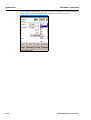
CM2-GTX100-2005
AT9000 Advanced Transmitter
Electronic Differential Pressure/
Pressure Transmitter
with DE® and HART®
Bilingual Communications
User’s Manual
NOTICE
While the information in this manual is presented in good faith and
believed to be accurate, Yamatake Corporation disclaims any implied
warranty of merchantability or fitness for a particular purpose and
makes no express warranties except as may be stated in its written
agreement with and for its customer.
In no event shall Yamatake Corporation be liable to anyone for any
indirect, special or consequential damages. This information and
specifications in this document are subject to change without notice.
© 2008 by Yamatake Corporation. All rights reserved.
Safety
Instructions
Preface
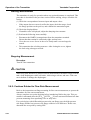
Correct installation and periodic maintenance are essential to the safe use of your differential pressure transmitters.
Read the safety instructions provided in this manual carefully and understand them
fully before starting installation, operation, and maintenance work.
Inspection
On delivery, make sure that the specifications are correct and check for any damage
that may have occurred during transportation. This equipment was tested under a strict
quality control program before shipment. If you find any problem in the quality specifications, please contact your Yamatake Corporation representative immediately, providing the model name and serial number.
The name plate is mounted on the neck of the enclosure.
Precautions
The following symbols are used in this manual to ensure user safety.
WARNING
This symbol is used to warn of hazards where failure to observe a safety instruction
may result in death or serious injury.
CAUTION
This symbol is used to warn of hazards where failure to observe a safety instruction
may result in injury or physical damage.
To ensure safe operation, be sure to observe the safety instructions provided on the
next page.
Yamatake Corporation will assume no responsibility, or offer any guarantee for any
failure resulting from violation of these safety instructions.
AT9000 Advanced Transmitter
i
WARNING!
This transmitter is a BILINGUAL transmitter that will communicate via
the DE Protocol or the HART Protocol.
Before connecting any communicator to a transmitter, the process loop
must be set to the MANUAL mode.
When a HART communicator is first connected to an active current loop
that has not been set to the MANUAL mode, a possibility exists that the
transmitter output will surge because of the capacitance of a HART communicator.
This output surge can cause the LOSS OF PROCESS CONTROL and
result in PHYCICAL DAMAGE AND PERSONAL INJURY!!!
CAUTION!
There are some characters which cannot be used on CommPad, even
though they are permitted by the HART protocol.
AT9000 Advanced Transmitter
ii
Yamatake Corporation
Safety
Safety Manual
WARNING
Follow the instructions and procedures in this manual when the transmitter is used in
SIS (Safety Instrumented Systems). Following description is applied when the
AT9000 Advanced Transmitter model code Q1 of Option, "Safety Transmitter" is
selected.
1. Application
Pressure measurements that shall meet the safety requirements according to
IEC61508.
2. Safety related characteristics
2.1 Safety Integrity Level
The AT9000 can be used up to SIL2 application as in single use or SIL3 application as
in dual use.
2.2 Start up
The safety output signal will be effective within 2 seconds after the start-up.
2.3 Safety Accuracy
The safety accuracy is +/-2% or +/-4% depending on models used.
2.4 Diagnostics time
The failures of the AT9000 can be detected within 5 minutes after they occur. The
burnout signal can be output within 5 sec. after detecting the internal faults.
Item
Specification
Mode of operation
Low demand mode
SIL
SIL2 (in single use)
Device type
HFT
AT9000 Advanced Transmitter
Type B
0 (in single use)
iii
Safety
Yamatake Corporation
3. Safety functions
3.1 Safety- relevant signal
The safety relevant signal of the AT9000 is the analog output signal 4 to 20 mA. All
safety functions refer to this analog output. The contact output or the digital output signal is not the safety relevant signal.
3.2 Normal Output
The analog current signal in the normal operating range of 3.6 to 21.6 mA including
normal over range and under range is output.
3.3 Burnout output
The output will be driven to the Hi/Lo limit according to the setting.
In the following cases, the output will be driven to LO limit regardless of the burnout
direction setting.
• Watchdog timer reset
• Internal voltage fault
• Readback error
After the detection of internal faults the AT9000 drives the signal to the fail alarm current of < 3.6 mA or > 21.6 mA.
In case of NE-43 option, after the detection of the internal faults the AT9000 drives the
signal to the fail alarm current of = 3.6 mA or = 21.0 mA.
4. Non safety compliant activities
The transmitter output is not safety-compliant during the following activities
• Configuration modifications
• Multidrop
• Simulation
• Test of the safety function
During transmitter configuration and maintenance work on the AT9000, alternative
measures must be taken to guarantee process safety.
5. Settings
6. Before start using
6.1 Safety- relevant signal
Before start using the AT9000 after installation, the following parameters shall be set.
iv
Yamatake Corporation
Safety
Burnout direction
Write protect switch note
Note: The communicator shall not be used during the normal operation when the
AT9000 is used in SIS as a safety transmitter.
7. Maintenance and repair
7.1 Maintenance and repair
Maintenance and repair shall be performed by a skilled and knowledgeable engineer.
7.2 Proof test
The procedure of the proof test is shown below. The test will cover 59% of possible
DU failures.
i)
Bypass PLC or take other appropriate action to avoid a false trip.
ii)
Use the Communicator to retrieve any diagnostics and take appropriate action.
iii)
Use the Communicator to change the mode to B/O simulation mode.
iv)
Verify the output signal of B/O Hi.
v)
Verify the output signal of B/O Lo.
vi)
Return to normal operation
vii) Remove the bypass from the PLC.
The following would be added to the above test. The tests including the following will cover 99% of possible DU failures.
viii) Apply pressure to verify the output at 0%, 20%, 40%, 60%, 80% and 100%.
8. Terms and Abbreviation
SIS: Safety Instrumented Systems
SIL: Safety Integrity Level
HFT: Hardware Fault Tolerance
PFD: Probability of Failure on Demand
PLC: Programmable Logic Controller
B/O: Burnout (It means fail alarm status)
DU: Dangerous Undetected
AT9000 Advanced Transmitter
v
Safety
Yamatake Corporation
Precautions
General Precautions
1. Checking the Product
When you accept the AT9000 Advanced Transmitter, check its appearance to make
sure that it is not damaged.
An Advanced Transmitter with semi-standard or special specifications may have different accessories.
2. Check the specifications
The specifications are marked on the name plate on the outside of the transmitter case.
Make sure that the specifications match your order by referring to the specifications.
In making an inquiry, identify the model No. and the product No.
3. Transportation
We recommend to transport the transmitter to the installation site in the packaged state
in order to prevent damages from occurring during transportation.
4. Storage Environment
(1) Storage location
During storage, protect the transmitter from rain water as well as from heavy vibration
and shock. Store it at normal temperature and humidity (about 25°C, 65%RH) as much
as possible.
(2) Store the transmitter in original packaging if possible.
(3) If a used transmitter must be stored for some period, wash it thoroughly after making sure that no fluid remains in the pressure receiving section.
5. Installation Environment
In order to maintain the original performance and reliability for a long time, install the
transmitter in the following environment:
(1) Ambient temperature
(a) The temperature gradient and temperature changes in installation environment
should be as small as possible.
(b) If a transmitter is exposed to heat radiated from the process side, lower its
ambient temperature as much as possible by insulating it or by selecting a wellventilated location for installation.
(c) If a process fluid can freeze, prevent freezing by means of heat insulation.
(2) Environment
Avoid corrosive environment as much as possible.
vi
Yamatake Corporation
Safety
Install in explosion proof and intrinsically safe conditions.
(3) Shock and vibration
Install the transmitter where shocks and vibrations will be as small as possible.
6. Application of Pressure to transmitter
In applying pressure to this transmitter, observe the following rules.
(1) The locking bolts of the adapter flange are loose when shipped. Tighten them to
the specified torque.
(2) Do not apply a pressure that exceeds the specified level.
(3) Do not tighten or loosen bolts while pressure is being applied to the transmitter.
(4) When a transmitter is used for measuring a poisonous substance, handle it carefully even after the pressure is released.
7. Electronic Parts
(1) This transmitter has several CMOS electronic components. Since static electricity
can easily cause the functional destruction of a CMOS component, never directly
touch them or touch a circuit with your hands.
(2) Is components must be touched, equalize the potential of the components before
doing so.
(3) When the printed wiring board (PWB) is removed, protect it in a non-conductive
bag.
8. Contact us
Yamatake Corporation
Advanced Automation Company
A-12-2 Kawana, Fujisawa-shi
Kanagawa-ken, 25A-8522, Japan
AT9000 Advanced Transmitter
vii
Safety
Yamatake Corporation
Explosion protected Models
FM Explosionproof / Dust-ignition proof Approval
CAUTION
· Install the apparatus only in areas for which the apparatus has been approved.
· Do not open the apparatus enclosure when an explosive atmosphere is present.
Marking information
Explosionproof for Class I, Division 1, Groups A, B, C and D; Class I, Zone 1, AEx d
IIC
Dust-Ignitionproof for Class II, III, Division 1, Groups E, F and G
T5 -40°C < Tamb < +85°C
Hazardous locations
Indoor / Outdoor Type 4X, IP67
Factory sealed, conduit seal not required for Division applications
Caution - Use supply wires suitable for 5°C above surrounding ambient
Instruction for safe use
Installations shall comply with the relevant requirements of the National Electrical
Code® (ANSI / FAPA 70).
viii
Yamatake Corporation
Safety
FM Intrinsically safe, Nonincendive and Suitable Approvals
1 Rating information
1.1 Intrinsically safe
Intrinsically Safe for use in Class I, Division 1, Groups A, B, C and D; Class II, Division 1, Groups E, F and G; Class III, Division 1; Class I, Zone 0, AEx ia IIC; T4
-40 °C < Tamb < +60 °C
Hazardous (Classified) Locations; Indoor/Outdoor Enclosure TYPE 4X, IP67;
For entity parameters see control drawings 80395278, 80395279 and 80395280.
1.2 Nonincendive and Suitable
Nonincendive, with Nonincendive Field Wiring Parameters, for use in Class I, Division 2, Groups A, B, C and D, T4; Class I, Zone 2, Group IIC, T4; Suitable for Class II
& III, Division 2, Groups E, F and G, T4; -40 °C < Tamb < +60 °C; Hazardous (Classified) Locations;
Indoor/Outdoor Enclosure TYPE 4X, IP67;
For Nonincendive Field Wiring parameters see control drawing 80395494.
2 Applicable standards
- FM Class 3600:1998 Electrical Equipment for Use in Hazardous (Classified) Locations - General Requirements
- FM Class 3610:2007 Intrinsically Safe Apparatus and Associated Apparatus for Use
in Class I, II & III, Division 1, Hazardous (Classified) Locations
- FM Class 3611:2004 Nonincendive Electrical Equipment for Use in Class I & II,
Division 2, and Class III, Divisions 1 & 2, Hazardous (Classified) Locations
- FM Class 3810:2005 Electrical Equipment for Measurement, Control and Laboratory
Use
- ANSI/ISA-12.00.01(IEC 60079-0 Mod):1999 Electrical Apparatus for Use in Class
I, Zones 0, 1 & 2 Hazardous (Classified) Locations - Part 0: General Requirements
- ANSI/ISA-12.02.01(IEC 60079-11 Mod):2002 Electrical Apparatus for Use in Class
I, Zones 0, 1 & 2 Hazardous (Classified) Locations - Part 11: Intrinsic Safety "i"
- ANSI/ISA-82.02.01(IEC 61010-1 Mod):2004 Safety Requirements for Electrical
Equipment for Measurement, Control, and Laboratory Use - Part 1: General Requirements
- ANSI/IEC 60529:2004 Degrees of Protection Provided by Enclosures (IP Code)
- ANSI/NEMA 250:1991 Enclosures for Electrical Equipment (1,000 Volts Maximum)
AT9000 Advanced Transmitter
ix
Safety
Yamatake Corporation
3 Instruction for safe use
3.1 Installations shall comply with the relevant requirements of the National Electrical Code® (ANSI/NFPA 70).
3.2 Installations shall comply with the latest edition of the manufacturer's instruction
manual.
IS models shall be installed in accordance with control drawings 80395278,
80395279 and 80395280, and NI models shall be installed in accordance with
control drawing 80395494.
3.3 The intrinsically safe associated apparatus must be FM Approvals approved.
3.4 Control room equipment connected to the associated apparatus should not use or
generate more than 250 Vrms or VDC.
3.5 See ANSI/ISA RP12.06.01, Installation of Intrinsically Safe Systems for Hazardous (Classified) Locations, for guidance on the installation of intrinsically safe
apparatus and systems.
3.6 Tampering and replacement with non-factory components may adversely affect
the safe use of the system.
3.7 Insertion or withdrawal of removable electrical connectors is to be accomplished
only when the area is known to be free of flammable vapors.
3.8 For ambient temperatures below -10 ºC (+14 ºF) and above +60 ºC (+140 ºF) use
field wiring suitable for both minimum and maximum ambient temperatures.
3.9 Use copper, copper-clad aluminum or aluminum conductors only.
3.10 The recommended tightening torque for field wiring terminals is 0.8 N·m (7
in.·lb) or greater, as specified.
3.11 A dust-tight conduit seal shall be used when installed in Class II & III environments.
3.12 WARNING - SUBSTITUTION OF COMPONENTS MAY IMPAIR INTRINSIC
SAFETY
3.13 WARNING - SUBSTITUTION OF COMPONENTS MAY IMPAIR SUITABILITY FOR DIVISIONS 1 & 2 AND ZONES 0, 1 & 2
3.14 WARNING - DO NOT DISCONNECT EQUIPMENT UNLESS AREA IS
KNOWN TO BE NONHAZARDOUS
3.15 WARNING - FOR CONNECTION ONLY TO NON-FLAMMABLE PROCESSES
Manual No. CM2-GTX100-2001
x
Yamatake Corporation
Safety
ATEX Flameproof and Dust Certifications
1. Marking information
0344
KEMA 08ATEX0004
II 1/2 G Ex d IIC T6 TPROCESS = 85 °C -30 °C < Tamb < +75 °C IP66 / 67
II 1/2 G Ex d IIC T5 TPROCESS = 100 °C -30 °C < Tamb < +80 °C IP66 / 67
II 1/2 G Ex d IIC T4 TPROCESS = 110 °C -30 °C < Tamb < +80 °C IP66 / 67
II 2 D Ex tD A21 IP66 / 67 T85 TPROCESS = 85 °C -30 °C < Tamb < +75 °C
II 2 D Ex tD A21 IP66 / 67 T100 TPROCESS = 100 °C -30 °C < Tamb < +75 °C
II 2 D Ex tD A21 IP66 / 67 T110 TPROCESS = 110 °C -30 °C < Tamb < +75 °C
2. Applicable standards
- EN 60079-0: 2006 Electrical apparatus for explosive gas atmospheres - Part 0: General requirements
- EN 60079-1: 2007 Electrical apparatus for explosive gas atmospheres - Part 1:
Flameproof enclosures "d"
- EN 60079-26: 2007 Explosive atmospheres - Part 26: Equipment with equipment
protection level (EPL) Ga
- EN 6124A-0: 2006 Electrical apparatus for use in the presence of combustible dust Part 0: General requirements
- EN 6124A-1: 2004 Electrical apparatus for use in the presence of combustible dust Part 1: Protection by enclosures "tD"
- EN 60529:1992 Degree of protection provided by enclosures (IP code)
3. Instruction for safe use
3.1 To maintain the degree of protection of at least IP 66 in accordance with IEC
60529, suitable cable entries must be used and correctly installed. Unused openings must be closed with a suitable stopping plug.
3.2 Use supply wires suitable for 5 °C above surrounding ambient.
3.3 When Model No. is given with GTXxxx-x ... x-yx ... x-x …,
if y=A, the thread type of the end of all entries is 1/2NPT, or
if y=B, the thread type of the end of all entries is M20.
4. Special conditions for safe use
4.1 The barrier diaphragm shall not be subjected environmental conditions which
might adversely affect the partition wall.
AT9000 Advanced Transmitter
xi
Safety
Yamatake Corporation
4.2 Repairs of flameproof joints are allowed only by manufacturer.
4.3 The equipment must be returned to the manufacturer in case of failure.
Manual No. CM2-GTX100-2001
xii
Yamatake Corporation
Safety
ATEX Intrinsic safety, Type n and Dust Certifications
1. Marking information
1.1 Intrinsic safety and Dust
0344
KEMA 07ATEX0200X
II 1 G Ex ia IIC T4 TPROCESS = 105 °C -30 °C < Tamb < +60 °C IP66 / 67
ELECTRICAL PARAMETERS: Ui = 30 V, Ii = 93 mA, Pi = 1 W, Ci = 5 nF, Li =
0.5 mH
II 1 D Ex iaD 20 IP66 / 67 T105 TPROCESS = 105 °C -30 °C < Tamb < +60 °C
1.2 Type n and Dust
KEMA 07ATEX0200X
II 3 G Ex nL IIC T4 TPROCESS = 105 °C -30 °C < Tamb < +60 °C IP66 / 67
ELECTRICAL PARAMETERS: Ui = 30 V, Ci = 5 nF, Li = 0.5 mH
II 2 D Ex tD A21 IP66 / 67 T85 TPROCESS = 85 °C -30 °C < Tamb < +75 °C
II 2 D Ex tD A21 IP66 / 67 T100 TPROCESS = 100 °C -30 °C < Tamb < +80 °C
II 2 D Ex tD A21 IP66 / 67 T110 TPROCESS = 110 °C -30 °C < Tamb < +80 °C
2. Applicable standards
- EN 60079-0:2006 Electrical apparatus for explosive gas atmospheres - Part 0: General requirements
- EN 60079-11:2007 Explosive atmospheres - Part 11: Equipment protection by intrinsic safety "i"
- EN 60079-15:2005 Electrical apparatus for explosive gas atmospheres - Part 15:
Construction, test and marking of type of protection "n" electrical apparatus
- EN 60079-26:2006 Explosive atmospheres - Part 26: Equipment with equipment
protection level (EPL) Ga
- EN 6124A-0:2006 Electrical apparatus for use in the presence of combustible dust Part 0: General requirements
- EN 6124A-1:2004 Electrical apparatus for use in the presence of combustible dust Part 1: Protection by enclosures "tD"
- EN 6124A-11:2006 Electrical apparatus for use in the presence of combustible dust Part 11: Protection by intrinsic safety "iD"
3. Instruction for safe use
3.1 To maintain the degree of protection of at least IP 66 in accordance with IEC
60529, suitable cable entries must be used and correctly installed. Unused openings must be closed with a suitable stopping plug.
3.2 Thread type of entry
AT9000 Advanced Transmitter
xiii
Safety
Yamatake Corporation
When Model No.is given with GTXxxx-x ... x-yx ... x-x ...
If y=A, the thread type of entries is 1/2NPT, or
if y=B, the thread type of entries is M20.
4. Special conditions for safe use of intrinsic safety Ex ia (X certificate)
Because the enclosure of Model GTX is made of aluminium, if it is mounted in an area
where the use of 1 G apparatus is required, it must be installed such, that, even in the
event of rare incidents, ignition sources due to impact and friction sparks are excluded.
Manual No. CM2-GTX100-2001
xiv
Yamatake Corporation
Safety
IECEx Flameproof and Dust Certifications
1. Marking information
IECEx KEM 08.0001
Ga/Gb Ex d IIC T6 TPROCESS = 85 °C -30 °C < Tamb < +75 °C IP66 / 67
Ga/Gb Ex d IIC T5 TPROCESS = 100 °C -30 °C < Tamb < +80 °C IP66 / 67
Ga/Gb Ex d IIC T4 TPROCESSS = 110 °C -30 °C < Tamb < +80 °C IP66 / 67
Ex tD A21 IP66 / 67 T85 TPROCESS = 85 °C -30 °C < Tamb < +75 °C
Ex tD A21 IP66 / 67 T100 TPROCESS = 100 °C -30 °C < Tamb < +75 °C
Ex tD A21 IP66 / 67 T110 TPROCESS = 110 °C -30 °C < Tamb < +75 °C
2. Applicable standards
- IEC 60079-0:2004 Electrical apparatus for explosive gas atmospheres - Part 0: General requirements
- IEC 60079-1:2007 Explosive atmospheres - Part 1: Equipment protection by flameproof enclosures "d"
- IEC 60079-26:2006 Explosive atmospheres - Part 26: Equipment with equipment
protection level (EPL) Ga
- IEC 6124A-0:2004 Electrical apparatus for use in the presence of combustible dust Part 0: General requirements
- IEC 6124A-1:2004 Electrical apparatus for use in the presence of combustible dust Part 1: Protection by enclosures "tD"
- IEC 60529:2001 Degree of protection provided by enclosures (IP code)
3. Instruction for safe use
3.1 To maintain the degree of protection of at least IP 66 in accordance with IEC
60529, suitable cable entries must be used and correctly installed. Unused openings must be closed with a suitable stopping plug.
3.2 Use supply wires suitable for 5 °C above surrounding ambient.
3.3 When Model No. is given with GTXxxx-x ... x-yx ... x-x …,
if y=A, the thread type of the end of all entries is 1/2NPT, or
if y=B, the thread type of the end of all entries is M20.
4. Special conditions for safe use
4.1 The barrier diaphragm shall not be subjected environmental conditions which
might adversely affect the partition wall.
4.2 Repairs of flameproof joints are allowed only by manufacturer.
4.3 The equipment must be returned to the manufacturer in case of failure.
Manual No. CM2-GTX100-2001
AT9000 Advanced Transmitter
xv
Safety
Yamatake Corporation
IECEx Intrinsic safety, Type n and Dust Certifications
1. Marking information
1.1 Intrinsic safety and Dust
IECEx KEM 07.0058X
Zone 0 Ex ia IIC T4 TPROCESS = 105 °C -30 °C < Tamb < +60 °C IP66 / 67
ELECTRICAL PARAMETERS: Ui = 30 V, Ii = 93 mA, Pi = 1 W, Ci = 5 nF, Li = 0.5 mH
Ex iaD 20 IP66 / 67 T105 TPROCESS = 105 °C -30 °C < Tamb < +60 °C
1.2 Type n and Dust
IECEx KEM 07.0058X
Ex nL IIC T4 TPROCESS = 105 °C -30 °C < Tamb < +60 °C IP66 / 67
ELECTRICAL PARAMETERS: Ui = 30 V, Ci = 5 nF, Li = 0.5 mH
Ex tD A21 IP66 / 67 T85 TPROCESS = 85 °C -30 °C < Tamb < +75 °C
Ex tD A21 IP66 / 67 T100 TPROCESS = 100 °C -30 °C < Tamb < +80 °C
Ex tD A21 IP66 / 67 T110 TPROCESS = 110 °C -30 °C < Tamb < +80 °C
2. Applicable standards
- IEC 60079-0:2004 Electrical apparatus for explosive gas atmospheres - Part 0: General requirements
- IEC 60079-11:2006 Explosive atmospheres - Part 11: Equipment protection by
intrinsic safety "i"
- IEC 60079-15:2005 Electrical apparatus for explosive gas atmospheres - Part 15:
Construction, test and marking of type of protection "n" electrical apparatus
- IEC 60079-26:2006 Explosive atmospheres - Part 26: Equipment with equipment
protection level (EPL) Ga
- IEC 6124A-0:2004 Electrical apparatus for use in the presence of combustible dust Part 0: General requirements
- IEC 6124A-1:2004 Electrical apparatus for use in the presence of combustible dust Part 1: Protection by enclosures "tD"
- IEC 6124A-11:2005 Electrical apparatus for use in the presence of combustible dust
- Part 11: Protection by intrinsic safety "iD"
3. Instruction for safe use
3.1 To maintain the degree of protection of at least IP 66 in accordance with IEC
60529, suitable cable entries must be used and correctly installed. Unused openings must be closed with a suitable stopping plug.
3.2 Thread type of entry
xvi
Yamatake Corporation
Safety
When Model No.is given with GTXxxx-x ... x-yx ... x-x ...
If y=A, the thread type of entries is 1/2NPT, or if y=B, the thread type of entries is
M20.
4. Special conditions for safe use of intrinsic safety Ex ia (X certificate)
Because the enclosure of Model GTX is made of aluminium, if it is mounted in an area
where the use of 1 G apparatus is required, it must be installed such, that, even in the
event of rare incidents, ignition sources due to impact and friction sparks are excluded.
Manual No. CM2-GTX100-2001
AT9000 Advanced Transmitter
xvii
Safety
Yamatake Corporation
NEPSI Flameproof and Dust Certifications
AT9000 Advanced Transmitter type GTX Series, manufactured by Yamatake Corporation, has been approved by National Supervision and Inspection Center for Explosion
Protection and Safety of Instrumentation (NEPSI) in accordance with the following
standards:
GB3836.1 - 2000
Electrical apparatus for explosive gas atmospheres
Part 1: General requirements
GB3836.2 - 2000
Electrical apparatus for explosive gas atmospheres
Part 2: Flameproof enclosure "d"
GB12476.1 - 2000
Electrical apparatus for use in the presence of combustible dust
Part A-1: Electrical apparatus protected by enclosures and surface temperature limitation - Specification for apparatus
Transmitters are approved with Ex marking of Ex d IIC T4~T6; DIP A21 TA85°C /
DIP A21 TA100°C / DIP A21 TA115°C. The certificate number is GYJ071268.
1. REQUIREMENTS FOR SAFE USE
1.1 The external earthing terminal shall be connected to the ground reliably at site.
1.2 The relationships between Ex marking, ambient temperature range and the maximum process temperature are shown below:
Ex marking
Ambient temperature
range
Maximum process
temperature
Ex d IIC T6DIP A21 TA85°C
-40°C ~ +75°C
80°C
Ex d IIC T5DIP A21 TA100°C
-40°C ~ +80°C
95°C
Ex d IIC T4DIP A21 TA115°C
-40°C ~ +80°C
110°C
1.3 The cable entry holes have to be connected by means of suitable cable entries
with type of protection of Ex d IIC. The cable entries shall be approved by NEPSI
in accordance with GB3836.A-2000, GB3836.2-2000 and GB12476.A-2000,
which are covered by a separate examination certificate. The screws of the cable
entries shall be 1/2-14NPT. Unwanted entry holes shall be blocked by blind plugs.
After installation of the cable entry, the whole apparatus shall reach IP66/IP67.
1.4 The warning "Do not open while the circuit is alive" must be obeyed when the
product is used in the explosive gas area.
1.5 Rated supply voltage: 10.8 ~ 42Vd.c. or 9 ~ 32Vd.c.
1.6 End users are forbidden to change the configuration to ensure the explosion protection performance of the product.
1.7 Regular cleanness shall be conducted to avoid the deposit of the dust.
xviii
Yamatake Corporation
Safety
1.8 When installation, operation and maintenance the product, users should comply
with the relevant requirements of the product instruction manual and the following standards:
GB3836.13-1997 "Electrical apparatus for explosive gas atmospheres Part 13:
Repair and overhaul for apparatus used in explosive gas atmospheres"
GB3836.15-2000 "Electrical apparatus for explosive gas atmospheres- Part 15:
Electrical installations in hazardous area (other than mines)"
GB3836.16-2006 "Electrical apparatus for explosive gas atmospheres Part 16:
Inspection and maintenance of electrical installation (other than mines)".
GB50257-1996 "Code for construction and acceptance of electric device for
explosion atmospheres and fire hazard electrical equipment installation engineering"
GB12476.2-2006 "Electrical apparatus for use in the presence of combustible
dust Part A-1: Electrical apparatus protected by enclosures and surface temperature limitation-Selection, installation and maintenance"
GB15577-1995 "Safety regulations for the protection of dust explosion".
AT9000 Advanced Transmitter
xix
Safety
Yamatake Corporation
NEPSI Intrinsic Safety Certification
AT9000 Advanced Transmitter type GTX Series, manufactured by Yamatake Corporation, has been approved by National Supervision and Inspection Center for Explosion
Protection and Safety of Instrumentation (NEPSI) in accordance with the following
standards:
GB3836.1 - 2000
Electrical apparatus for explosive gas atmospheres
Part 1: General requirements
GB3836.4 - 2000
Electrical apparatus for explosive gas atmospheres
Part 4: Intrinsic safety "i"
GB3836.8 - 2000
Electrical apparatus for explosive gas atmospheres
Part 8: Type of protection "n"
Transmitters is approved with Ex marking of Ex ia IICT4; Ex nL IICT4. The certificate number is GYJ071269.
1.REQUIREMENTS FOR SAFE USE
1.1 The relationships between Ex marking, ambient temperature range and maximum
process temperature are shown in the table below:
Ex marking
Ambient temperature
range
Maximum process
temperature
Ex ia IICT4
-40°C ~ +60°C
105°C
Ex nL IICT4
-40°C ~ +60°C
110°C
1.2 Only be connected to a certified associated apparatus or a certified associated
energy-limited apparatus, the product could be used in the explosive atmosphere.
The connection shall be accordance with the requirements of the manual of the
associated apparatus and the product.
1.2.1 Intrinsically safe parameters:
Max. input Voltage
Ui (V)
Max. input current
Ii (mA)
Max. input power
Pi (W)
30
100
1
Max. internal parameter
Ci (nF)
Li (mH)
13
0.5
1.2.2 The cable with shield is suitable for connection, the cross-sectional area of the
wire shall be at least 0.5 mm2, and the shield shall be connected to the earth in the
non-hazardous area.
1.3 End users are forbidden to change the configuration to ensure the explosion protection performance of the product.
xx
Yamatake Corporation
Safety
1.4 When installation, operation and maintenance the product, users should comply
with the relevant requirements of the product instruction manual and the following standards:
GB50257-1996 "Code for construction and acceptance of electric device for
explosion atmospheres and fire hazard electrical equipment installation engineering".
GB3836.13.1997 "Electrical apparatus for explosive gas atmospheres Part
13:Repair and overhaul for apparatus used in explosive gas atmospheres".
GB3836.15-2000 "Electrical apparatus for explosive gas atmospheres- Part 15:
Electrical installations in hazardous area (other than mines)"
GB3836.16-2006 "Electrical apparatus for explosive gas atmospheres- Part 16:
Inspection and maintenance of electrical installation (other than mines)".
AT9000 Advanced Transmitter
xxi
MEMO
Table of Contents
Safety
Chapter 1 : Overview-First Time Users Only
1.1 : Introduction ......................................................................................................1-1
1.2 : AT9000 Advanced Transmitters ......................................................................1-1
1.3 : Parts names of the transmitter.........................................................................1-2
1.4 : Transmitter Order ............................................................................................1-4
Chapter 2 : Installation
2.1 : Introduction ......................................................................................................2-1
2.2 : Mounting AT9000 Advanced Transmitter ........................................................2-1
2.3 : Piping AT9000 Advanced Transmitter .............................................................2-8
2.3.1 : Piping for Liquid, Gas or Steam Flow Rate Measurement .................2-11
2.3.2 : Pressure Measurement - Piping .........................................................2-14
2.3.3 : Liquid Level Measurement - Piping (GTX_ _D/GTX_ _G)..................2-16
2.4 : Wiring AT9000 Advanced Transmitter.............................................................2-21
2.4.1 : Wiring for Transmitter -- Regular Model .............................................2-21
Chapter 3 : Operation of the Transmitter
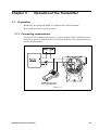
3.1 : Preparation ......................................................................................................3-1
3.1.1 : Connecting communicator..................................................................3-1
3.1.2 : HART® 375 FIELD COMMUNICATOR keyboard ..............................3-2
3.1.3 : Symbols on communicator screen .....................................................3-2
3.1.4 : Keying in alphanumeric characters ....................................................3-2
3.2 : Setting and Checking Specifications ...............................................................3-3
3.2.1 : Establishing Communications ............................................................3-3
3.2.2 : Setting Tag No....................................................................................3-4
3.2.3 : Checking Output Format ....................................................................3-4
3.2.4 : Checking Display Setting....................................................................3-4
3.2.5 : Display Mode......................................................................................3-5
3.2.6 : Display Function .................................................................................3-5
3.2.7 : Checking Engineering Unit of Measured Pressure.............................3-5
3.2.8 : Checking Low and High Limits of Setting Range ...............................3-5
3.2.9 : Adjusting Damping Time Constant .....................................................3-6
3.2.10 : Checking Fill fluid temperature compensation..................................3-6
3.3 : Measurement with model GTX_ _D.................................................................3-7
3.3.1 : Flow Rate Measurement ....................................................................3-7
3.3.2 : Gas Pressure Measurement...............................................................3-11
3.3.3 : Liquid Level Measurement of Open Tank and Closed Tank (Dry Leg) ........3-15
3.3.4 : Liquid Level Measurement of Closed Tank (Wet Leg) .......................3-19
3.4 : Measurement with Model GTX_ _D/GTX_ _A.................................................3-23
ST9000 Smart Transmitter Model : GTX
Table of Contents
3.4.1 : Pressure Measurement...................................................................... 3-23
3.5 : Measurement with Model GTX_ _F ................................................................ 3-27
3.5.1 : Pressure Measurement...................................................................... 3-27
3.6 : Measurement with Model GTX_ _U/GTX_ _R ................................................ 3-29
3.6.1 : Pressure Measurement...................................................................... 3-29
3.6.2 : Cautions Related to Flow Rate Measurement ................................... 3-30
3.7 : Measurement with Model GTX_ _U ................................................................ 3-31
3.7.1 : Pressure Measurement...................................................................... 3-31
3.8 : Set Range Calculation for Liquid Level Measurement .................................... 3-33
3.8.1 : Open Tank or Closed Tank (Dry Leg) or Remote Seal Set Range Calculation
...................................................................................................................... 3-33
3.8.2 : Closed Tank (Wet Leg or Remote Seal) -- Set Range....................... 3-38
3.9 : Indicator (Optional).......................................................................................... 3-41
3.9.1 : Display unit of indicator...................................................................... 3-41
3.9.2 : Bar Graph Display.............................................................................. 3-42
3.9.3 : External Zero/Span Adjustment Display ............................................ 3-42
3.9.4 : Square Root Extraction Display ......................................................... 3-43
3.9.5 : Write Protect Display ......................................................................... 3-43
3.9.6 : Status Record Display ....................................................................... 3-43
3.9.7 : Display Update Mark.......................................................................... 3-43
3.10 : External Zero/Span Adjustment function (Optional)..................................... 3-44
Chapter 4 : Operation Using HART® Communicator
4.1 : Starting Communications ................................................................................ 4-1
4.1.1 : Connecting communicator ................................................................. 4-1
4.1.2 : HART® 375 FIELD COMMUNICATOR keyboard ............................. 4-2
4.1.3 : Symbols on communicator screen..................................................... 4-2
4.1.4 : Keying in alphanumeric characters.................................................... 4-2
4.1.5 : Establishing communications............................................................. 4-3
4.1.6 : Checking basic data........................................................................... 4-3
4.2 : Configuration................................................................................................... 4-5
4.3 : Top menu ........................................................................................................ 4-5
4.4 : Process Variables menu summary ................................................................. 4-6
4.5 : Device menu summary ................................................................................... 4-7
4.6 : Diagnostic menu summary ............................................................................. 4-11
4.6.1 : Changing tag no................................................................................. 4-12
4.6.2 : Changing output format ..................................................................... 4-12
4.6.3 : Indicator display format...................................................................... 4-12
4.6.4 : Change Cutoff Mode.......................................................................... 4-13
4.6.5 : Selecting unit of measurement .......................................................... 4-14
4.6.6 : Setting range values .......................................................................... 4-14
4.6.7 : Adjusting damping time...................................................................... 4-14
4.7 : Start-up and Operation................................................................................... 4-15
ST9000 Smart Transmitter Model : GTX
Table of Contents
4.7.1 : Running analog output check .............................................................4-15
4.7.2 : Configuring ranges with applying pressure ........................................4-15
4.7.3 : Alarm Settings ....................................................................................4-16
4.7.4 : Write Protect.......................................................................................4-19
4.8 : Calibration........................................................................................................4-20
4.8.1 : Calibrating analog output signal .........................................................4-20
4.8.2 : Calibrating range ................................................................................4-21
4.8.3 : Resetting calibration ...........................................................................4-21
Chapter 5 : Maintenance
5.1 : Disassembly and Assembly.............................................................................5-2
5.1.1 : Before You Start .................................................................................5-2
5.1.2 : Mount Center Body Cover and Adapter Flange .................................5-3
5.1.3 : Washing the Center Body...................................................................5-5
5.2 : Calibrating Set Range and Output Signals ......................................................5-6
5.2.1 : Calibrating Set Range Based on Reference Input..............................5-6
5.2.2 : Calibrating Output Signals..................................................................5-9
Chapter 6: Troubleshooting
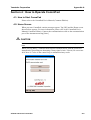
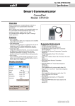
Appendix A - Supplement Manual for CommPad
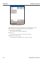
Section 1 : Introduction ............................................................................................A-1
Section 2 : How to Connect Your CommPad to the Advanced Transmitter ............A-2
Section 3 : Menu Structure ......................................................................................A-3
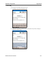
Section 4 : How to Operate CommPad....................................................................A-5
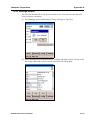
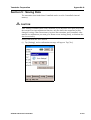
4.1: How to Start CommPad..........................................................................A-5
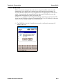
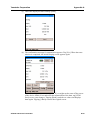
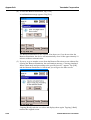
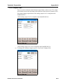
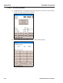
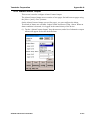
4.2: Home Screen..........................................................................................A-5
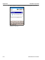
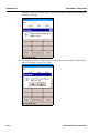
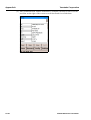
4.3: User Selection Screen............................................................................A-6
4.4: Summary Screen....................................................................................A-8
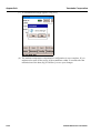
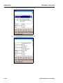
4.5: Status Screen .........................................................................................A-8
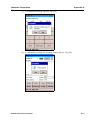
4.6: Help Screen............................................................................................A-9
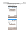
4.7: Configuration Screen..............................................................................A-10
4.8: Setup Screen..........................................................................................A-11
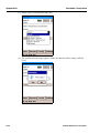
4.9: Maintenance Screen...............................................................................A-12
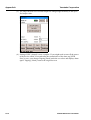
4.10: All Functions Screen.............................................................................A-13
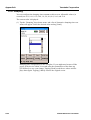
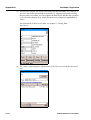
4.11: NVM Save ............................................................................................A-15
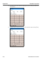
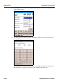
4.12: Tag .......................................................................................................A-17
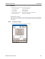
4.13: Range ...................................................................................................A-22
4.14: Remote-seal .........................................................................................A-27
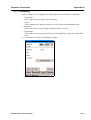
4.14.1: Auto Range (Closed Tank)........................................................A-28
4.14.2: Set LRV (Actual) .......................................................................A-36
4.14.3: Amb. Temp. Compensate .........................................................A-38
ST9000 Smart Transmitter Model : GTX
Table of Contents
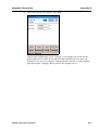
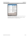
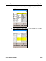
4.15: Display..................................................................................................A-46
4.16: Damping ...............................................................................................A-50
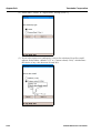
4.17: Conformity ............................................................................................A-51
4.18: Checking the Fail-safe Direction...........................................................A-56
4.19: Output Limit ..........................................................................................A-59
4.20: Memo....................................................................................................A-62
4.21: Monitoring.............................................................................................A-64
4.22: Adjustment............................................................................................A-65
4.22.1: Set LRV (0%) ............................................................................A-65
4.22.2: URV adjustment ........................................................................A-68
4.22.3: Set LRV (Actual) .......................................................................A-70
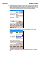
4.23: Calibration ............................................................................................A-73
4.23.1: Correct zero input......................................................................A-73
4.23.2: Correct LRV ..............................................................................A-76
4.23.3: Correct URV..............................................................................A-78
4.23.4: Restore factory settings ............................................................A-80
4.23.5: Reset corrections ......................................................................A-81
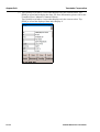
4.24: Output Mode.........................................................................................A-84
4.25: 4-20 mA Correct ...................................................................................A-89
4.26: PROM No. ............................................................................................A-91
4.27: Software Version ..................................................................................A-91
4.28: Sensor Temp. .......................................................................................A-92
4.29: DE/Analog Select (Switching between digital and analog communications
output)...................................................................................................A-93
4.30: DE Configuring .....................................................................................A-95
4.31: Records ................................................................................................A-96
4.31.1: Zero Calibr. Log in CommPad...................................................A-96
4.31.2: Zero Calibr. Log in Device.........................................................A-100
4.31.3: Status Records..........................................................................A-103
4.32: Alarm/Contact Output ...........................................................................A-107
4.33: Data Overwrite Protection ....................................................................A-114
4.34: Settings screen.....................................................................................A-115
Section 5 : Saving Data ...........................................................................................A-119
Section 6 : Troubleshooting .....................................................................................A-124
Appendix B - Damping time constant related calibration span
when shipped
ST9000 Smart Transmitter Model : GTX
List of Figure
Figure 1-1
Figure 1-2
Figure 1-3
Figure 2-1
Figure 2-2
Figure 2-3
Figure 2-4
Figure 2-5
Figure 2-6
Figure 2-7
Figure 2-8
Figure 2-9
Figure 2-10
Figure 2-11
Figure 2-12
Figure 2-13
Figure 2-14
Figure 2-15
Figure 2-16
Figure 2-17
Figure 2-18
Figure 2-19
Figure 2-20
Figure 2-21
Figure 2-22
Figure 3-1
Figure 3-2
Figure 3-3
Figure 3-4
Figure 3-5
Figure 3-6
Figure 3-7
Figure 3-8
Figure 3-9
Figure 3-10
Figure 3-11
Figure 3-12
Figure 3-13
Figure 3-14
Figure 3-15
Figure 3-16
Figure 3-17
Figure 4-1
Figure 4-2
Figure 4-3
Figure 4-4
Figure 4-5
Figure 5-1
Figure 5-2
Figure 5-3
Figure 5-4
Figure A-1
Figure A-2
AT9000 Advanced Transmitter Family ...................................................................... 1-2
Structure of the transmitter (model GTX _ _D) .......................................................... 1-2
Typical AT9000 Advanced Transmitter Order Components ...................................... 1-4
Typical Bracket Mounted and Flange Mounted Installations. .................................... 2-1
..................................................................................................................................... 2-2
..................................................................................................................................... 2-2
..................................................................................................................................... 2-3
Typical Flange Mounted Transmitter Installation....................................................... 2-3
Typical Remote DIaphragm Seal Transmitter Installation.......................................... 2-5
..................................................................................................................................... 2-5
Typical 3-Valve Manifold and Blow-Down Piping Arrangement. ............................. 2-8
Piping for Liquid Flow Rate Measurement - Example ............................................... 2-11
Piping for Gas Flow Rate Measurement - Example.................................................... 2-12
Piping for Steam Flow Rate Measurement - Example ................................................ 2-13
Gas Pressure Measurement - Piping............................................................................ 2-14
Example of Piping ....................................................................................................... 2-15
H mark on center body ................................................................................................ 2-16
Open Tank - Piping Example ...................................................................................... 2-17
Closed Tank - Piping (Dry-leg Sealing Example)....................................................... 2-18
Closed Tank - Piping (Wet-leg Sealing Example) ...................................................... 2-19
Wiring for transmitter without Alarm output .............................................................. 2-21
Wiring for transmitter with Alarm output ................................................................... 2-22
External Grounding or Bonding Connection............................................................... 2-23
Supply Voltage and External Load Resistance - Relationship.................................... 2-23
AT9000 Advanced Transmitter Terminal Block......................................................... 2-24
..................................................................................................................................... 3-1
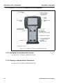
HART® 375 FIELD COMMUNICATOR ................................................................. 3-2
..................................................................................................................................... 3-27
..................................................................................................................................... 3-29
..................................................................................................................................... 3-31
Open Tank ................................................................................................................... 3-33
Closed Tank................................................................................................................. 3-33
..................................................................................................................................... 3-34
Open Tank ................................................................................................................... 3-35
Closed Tank................................................................................................................. 3-35
Open Tank ................................................................................................................... 3-36
Open Tank ................................................................................................................... 3-37
Closed Tank (Wet Leg) ............................................................................................... 3-38
Closed Tank (Wet Leg) ............................................................................................... 3-39
Closed Tank (Wet Leg) ............................................................................................... 3-40
Display unit of indicator.............................................................................................. 3-41
..................................................................................................................................... 3-44
..................................................................................................................................... 4-1
HART® 375 FIELD COMMUNICATOR ................................................................. 4-2
..................................................................................................................................... 4-17
..................................................................................................................................... 4-18
..................................................................................................................................... 4-19
Locking Case Cover .................................................................................................... 5-2
Center Body Cover Fixing Bolts ................................................................................. 5-3
Connection for calibration........................................................................................... 5-7
Connection for Calibration. ......................................................................................... 5-9
Wiring for connection with Model GTX..................................................................... A-2
Supply voltage vs. load resistance............................................................................... A-2
ST9000 Smart Transmitter Model : GTX
List of Table
Table 2-1
Table 2-2
Table 2-3
Table 2-4
Table 5-1
Table 5-2
Mounting Remote Diaphragm Seal Transmitter .............................................. 2-4
.......................................................................................................................... 2-6
Process Connections......................................................................................... 2-9
Installing Adapter Flange ................................................................................. 2-10
Cover Bolts / Nuts and Tightening Torque ...................................................... 5-4
Adapter Flange Bolt / Nut Tightening Torque ................................................. 5-4
ST9000 Smart Transmitter Model : GTX
Chapter 1 :
Overview-First Time Users Only
1.1 : Introduction
This section is intended for users who have never worked with our AT9000 Advanced
Transmitter. It provides some general information to acquaint you with the AT9000
Advanced Transmitter.
1.2 : AT9000 Advanced Transmitters
Yamatake’s AT9000 Advanced Transmitter includes model variations of these basic
pressure measurement types.
• Differential Pressure
• Gauge Pressure
• Absolute Pressure
Transmitter adjustments
Except for optional zero and span adjustments available with AT9000 Advanced
Transmitters only, the AT9000 Advanced Transmitter has no physical adjustments.
You need a CommPad or HART® 375 communicator to make adjustments to a
AT9000 Advanced Transmitter
GTX_ _ D
Differential
Pressure
GTX_ _ F
Differential
Pressure
with Flange
GTX_ _ R
DIfferential Pressure
with Remote Diaphragm Seals
GTX_ _ G
Gauge
Pressure
GTX_ _ A
Absolute
Pressure
GTX_ _ U
Gauge Pressure
with Remote DIaphragm Seal
Figure 1-1 AT9000 Advanced Transmitter Family
AT9000 Advanced Transmitter
1-1
Overview-First Time Users Only
Yamatake Corporation
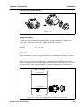
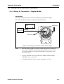
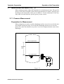
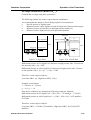
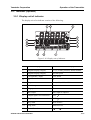
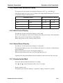
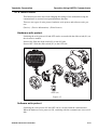
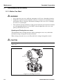
1.3 : Parts names of the transmitter
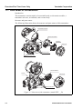
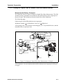
Introduction
This transmitter consists mainly of a terminal board, an electronics module, a
transmitter unit case, an indicator, and a center body.
Structure and parts names
The following illustration shows the structure and parts names of this transmitter:
Transmitter unit case
Electronics module
Indicator
Case cover
Blolts and nuts
Center body cover
Terminal Block
Sensor
Case cover
Blolts and nuts
Figure 1-2 Structure of the transmitter (model GTX _ _D)
1-2
AT9000 Advanced Transmitter
Yamatake Corporation
Parts name
Overview-First Time Users Only
Description
Center body
Consists of a composite semiconductor sensor, a pressure
diaphragm, an excessive pressure protection mechanism,
etc.
Center body cover
Two center body covers sandwich the center body. Process
connection is made to this part.
Bolts and nuts
Fixing the center body between covers, are a series of bolts
and nuts.
Sensor
Consists of a composite semiconductor sensor, a pressure
receiving diaphragm, a flange, a capillary tube, etc.
Electronics module
Consists of electronic circuits having functions for
processing differential pressure and other signals, and
transmitting them.
Transmitter unit case
Housing the electronics module and the terminal board.
Case cover
Encloses the transmitter unit case.
Indicator
It display output value, unit, error message, etc.
AT9000 Advanced Transmitter
1-3
Overview-First Time Users Only
Yamatake Corporation
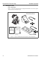
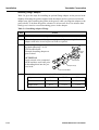
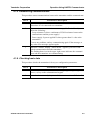
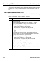
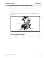
1.4 : Transmitter Order
Order components
Figure 1-3 shown the components that are shipped and should be received for a typical
AT9000 Advanced Transmitter order.
Mounting Bracket (Optional)
AT9000
User's
Manual
HART User's
Manual
HART User's Manual
(Optional)
Magnet stick (Optional)
Figure 1-3 Typical AT9000 Advanced Transmitter Order Components
1-4
AT9000 Advanced Transmitter
Chapter 2 :
Installation
2.1 : Introduction
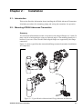
This section Provides information about installing the AT9000 Advanced Transmitter.
It includes procedures for mounting, piping and wiring the transmitter for operation.
2.2 : Mounting AT9000 Advanced Transmitter
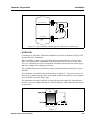
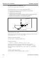
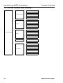
Summary
You can mount all transmitter models except those with integral flanges to a 2-inch (50
mm) vertical or horizontal pipe using our optional angle or flat mounting bracket or a
bracket of your own. Those models with integral flanges are supported by the flange
connection.
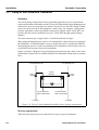
Figure 2-1 shows typical bracket mounted and flange mounted transmitter installations
for comparison.
Figure 2-1 Typical Bracket Mounted and Flange Mounted Installations.
AT9000 Advanced Transmitter
2-1
Installation
Yamatake Corporation
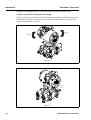
Methods of changing direction of indicator after mounted are shown below.
a) Rotate electronics housing 90° horizontally.
Loosen 3 mm set screw on outside neck of transmitter. Rotate electronics housing in a
maximum of 90 degree increments (left or right) from the center to a position you
require and tighten the set screw.
90 Max
90 Max
Figure 2-2
Set screw
(3mm)
Figure 2-3
2-2
AT9000 Advanced Transmitter
Yamatake Corporation
Installation
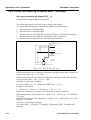
b) Rotate digital display module
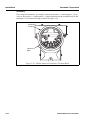
Figure 2-4
Flange mounting
To mount a flange mounted transmitter model, bolt the transmitter’s flange to the
flange pipe on the wall of the tank. Tighten the bolts to a torque of
SNB
: 20 ± 1 N • m
SUS304
: 10 ± 1 N • m
ATTENTION
On insulated tanks, remove enough insulation to accommodate the flange extension.
Figure 2-5 shows a typical installation for a transmitter with the flange on the high
pressure (HP) side so the HP diaphragm is in direct contact with the process fluid. The
low pressure (LP) side of the transmitter is vented to atmosphere (no connection).
100 % Liquid
0 % Liquid
Figure 2-5 Typical Flange Mounted Transmitter Installation.
AT9000 Advanced Transmitter
2-3
Installation
Yamatake Corporation
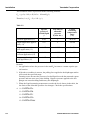
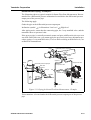
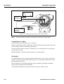
Remote seal mounting
Use the procedure in "Table 2-1Mounting Remote Diaphragm Seal Transmitter" to
mount a remote diaphragm seal transmitter model. Figure 2-6 shows a typical installation for a remote diaphragm seal transmitter for reference.
ATTENTION
Mount the transmitter flanges within the limits stated here for the given fill-fluid in the
capillary tubes with a tank at one atmosphere.
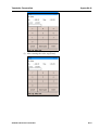
Table 2-1 Mounting Remote Diaphragm Seal Transmitter
Step
Action
1
Mount transmitter at a remote distance determined by length of capillary
tubing.
2
If Transmitter Model Number Is...
GTX35R
GTX40R
Then Connect Remote Seal on...
H mark side of transmitter to upper flange mounting on tank wall.
ATTENTION
On insulated tanks, remove enough insulation to accommodate the flange
extension.
3
If Transmitter Model Number is...
GTX35R
GTX40R
Then Connect Remote Seal on...
Opposite side of transmitter to lower flange mounting on tank wall.
ATTENTION
On insulated tanks, remove enough insulation to accommodate the flange
extension.
4
2-4
Tighten bolts to torque of
SNB7: 20 ± 1 N • m ,
SUS304: 10 ± 1 N • m .
AT9000 Advanced Transmitter
Yamatake Corporation
Installation
100 % Liquid Level
Fixed
Ref Leg
0 % Liquid Level
Figure 2-6 Typical Remote DIaphragm Seal Transmitter Installation
ATTENTION
Calculation of Allowable Transmitter Installation Location in Remote Seal Type Differential Pressure Transmitter.
When installing a remote seal type differential pressure transmitter on an enclosed
tank, we recommend the installation of the main unit below the lower flange. However, it is sometimes necessary to install the transmitter main unit between the upper
and lower flanges due to piping restrictions.
The condition that must be satisfied to ensure normal transmitter operations is specified here.
If a transmitter is installed in the position shown in Figure 2-7, the inner pressure of
the tank (P0) and the head pressure of the liquid sealed in the capillary can be applied
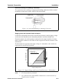
to its main unit (low limit flange side).
The transmitter functions normally as long as the pressure applied to its diaphragm
surface is equal to or higher than the low limit P (kPa abs.) of the allowable pressure of
its main unit.
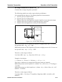
Figure 2-7
AT9000 Advanced Transmitter
2-5
Installation
Yamatake Corporation
This condition can be expressed with the following formula;
P 0 + ( ( ρ′h ) ⁄ 102 ) ≥ P ( 1kPa = 102mmH 2 O )
Therefore, h ≤ ( P 0 – P ) × 102 ⁄ ( ρ′ )
Table 2-2
Specific
gravity of
sealed liquid
ρ'
Low limit of
allowable
pressure
P (kPa abs.)
Liquid
contacting
temperature
range
(°C)
General application (*1)
0.935
2
-40 to 40
High temperature application (-*2)
1.07
2
-5 to 90
High temperature & vacuum application (*3)
1.07
0.1333
-5 to 50
High temperature & high
vacuum application (*4)
1.09
0.1333
-10 to 250
Oxygen application, chlorine application (*5)
1.87
53
-10 to 40
Remarks
1. An application where the pressure in the tank P0 becomes a vacuum requires special caution.
2. If the above condition is not met, the pulling force applied to the diaphragm surface
will exceed the specified range.
Foaming occurs because the pressure of sealed liquid exceeds the saturated vapour
pressure and can cause zero point shifting. Negative pressure applied to the diaphragm can cause buckling and destroy the diaphragm.
3. When the liquid contacting temperature exceeds the levels shown in the table, the
low limit of the allowable pressure also changes. Check the specifications.
4. *1. GTXR-A
*2. GTXR-B
*3. GTXR-C
*4. GTXR-D
*5. GTXR-H&J
2-6
AT9000 Advanced Transmitter
Yamatake Corporation
Installation
<Example of calculation>
Let’s take up an example in which a remote seal type transmitter of the of the general
specifications is used for a vacuum application (3kPa abs.)
•
Liquid contacting pressure
:Normal pressure (24°C)
•
Low limit of allowable pressure ( ρ ) :2 kPa abs. (15mmHg abs.)
•
Specific gravity of sealed liquid ( ρ′ ) :0.935
•
Inner pressure of tank ( ρ 0 )
:3kPa abs.
The condition that must be met to satisfy the transmitter specifications is as follows:
h ≤ ( P 0 – P ) × 102 ⁄ ( ρ′ )
h ≤ ( 3 – 2 ) × 102 ⁄ 0.935 = 109mm
Therefore, the high limit of the transmitter position is 109mm.
AT9000 Advanced Transmitter
2-7
Installation
Yamatake Corporation
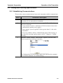
2.3 : Piping AT9000 Advanced Transmitter
Summary
The actual piping arrangement will vary depending upon the process measurement
requirements and the transmitter model. Except for flanged and remote diaphragm seal
connections, process connections are made to 1/4 inch or 1/2 inch NPT female connections in the process head of the transmitter’s meter body. For example, a differential
pressure transmitter comes with double ended process heads with 1/4 inch NPT connections but they can be modified to accept 1/2 inch NPT through optional flange
adapters.
The most common type of pipe used is 1/2 inch schedule 80 steel pipe.
Many piping arrangements use a three-valve manifold to connect the process piping to
the transmitter. A manifold makes it easy to install and remove a transmitter without
interrupting the process. It also accommodates the installation of blow-down valves to
clear debris from pressure lines to the transmitter.
Figure 2-8 shows a diagram of a typical piping arrangement using a three-valve manifold and blow-down lines for a differential pressure transmitter being used to measure
flow.
To Downstream Tap
To Upstream Tap
3-Valve
Manifold
Drain
Valve
To Low Pressure
Side of Transmitter
To Waste
Drain
Valve
To High Pressure
Side of Transmitter
To Waste
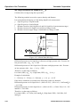
Figure 2-8 Typical 3-Valve Manifold and Blow-Down Piping Arrangement.
Process connections
Table describes typical process connections for a given type of transmitter.
2-8
AT9000 Advanced Transmitter
Yamatake Corporation
Installation
Table 2-3 Process Connections
Transmitter type
Process Connection
Differential Pressure
Process heads with 1/4 inch NPT internal thread
connection.
Flange adapters and manifolds with 1/2 inch
internal thread connections are optional.
Gauge Pressure
Process head with 1/2 inch NPT internal thread
connection.
Process heads with 1/4 inch NPT internal thread
connection. (GTXG)
Flange adapters and manifolds with 1/2 inch
internal thread connections are optional
(GTXG)
Absolute Pressure
Process heads with 1/2 inch NPT internal thread
connection (GTXA)
Flange Mounted Liquid
Level
1.5. 2 or 3 inches flange with flush or 2, 3 or 4
inches extended diaphragm on high pressure
side.
Reference side has standard differential pressure
process head.
Remote Diaphragm Seals
See Model Selection Guide for description of
available Flanged, Button-diaphragm (G1·1/2),
and Wafer type process connections.
AT9000 Advanced Transmitter
2-9
Installation
Yamatake Corporation
Installing flange Adapter
Table 2-4 gives the steps for installing an optional flange adapter on the process head.
Slightly deforming the gasket supplied with the adapter before you insert it into the
adapter may aid in retaining the gasket in the groove while you align the adapter to the
process head. To deform the gasket, submerse it in hot water for a few minutes then
firmly press it into its recessed mounting groove in the adapter.
Table 2-4 Installing Adapter Flange
Step
Action
1
Carefully seat FEP (white) gasket into adapter groove.
2
Thread adapter onto 1/2 inch process pipe and align mounting holes in
adapter with holes in end of process head as required.
3
Secure adapter to process head
by hand tightening 7/16-20
UNF hexhead bolts.
Example-Installing adapter on
process head
Process
Head
ATTENTION
Apply an anti-seize compound
on the stainless steel bolts prior
to threading them into the process head.
FEP Gasket
Adapter Flange
7/16 X 20 UNF Bolts
4
Evenly tighten adapter bolts to the following torque;
Adapter material
2-10
CS/SS
CS/SS
PVC
Bolt material
SNB7/SS630
SS304
SNB7/SS304
Torque N•m
20 ±1
10 ±0.5
7 ±0.5
AT9000 Advanced Transmitter
Yamatake Corporation
Installation
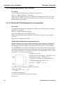
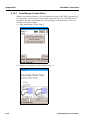
2.3.1 :Piping for Liquid, Gas or Steam Flow Rate Measurement
Recommended Piping - Example 1
The illustration shows a typical example for liquid Flow Rate Measurement. This Differential pressure transmitter is located below the differential pressure output port of
the process pipe.This minimizes the static head effect of the condensate.
The following apply:
Grade the pipe at the differential pressure output part.
Inclination symbol
in illustration: Low level
High level
After piping work, ensure that the connecting pipe, the 3-way manifold valve, and the
transmitter have no pressure leak.
Differential pressure output port
Orifice
Main valve
Inclination
Gasvent valve
Inclination
Differential pressure output port
Inclination
Main valve
High pressure side
Low pressure side
Inclination
Gas vent valve
Tee
Orifice
Inclination
Inclination
3-way
manifold valve
High pressure side
Vent / Drain plug
Low pressure side
Drain valve
Drain valve
Figure 2-9 Piping for Liquid Flow Rate Measurement - Example
This transmitter is located underneath the differential pressure output port of the process pipe.
AT9000 Advanced Transmitter
2-11
Installation
Yamatake Corporation
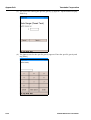
Recommended Piping - Example 2
The illustration shows a typical example for Gas Flow Rate Measurement. This Differential pressure transmitter is located above the differential pressure output port of the
process pipe.The condensate drains away from the transmitter.
The following apply:
Grade the pipe at the differential pressure output part.
Inclination symbol in illustration: Low level High level
After piping work, ensure that the connecting pipe, check for pressure leaks around the
3-way manifold valve, and the transmitter.
Differential pressure output port
Orifice
Main valve
Inclination
Gas vent plug
3-way manifold valve
High pressure side
Inclination
Low pressure side
Orifice
Differential pressure output port
Vent / Drain plug
Main valve
Inclination
Gas
vent plug
Inclination
High pressure side
Tee
Low pressure side
Figure 2-10 Piping for Gas Flow Rate Measurement - Example
This transmitter is located above the differential pressure output port of the process
pipe.
2-12
AT9000 Advanced Transmitter
Yamatake Corporation
Installation
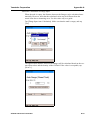
Recommended Piping - Example 3
The illustration shows a typical example for Steam Flow Rate Measurement. Recommended for a Differential pressure transmitter located below the differential pressure
output port of the process pipe.
The following apply:
Grade the pipe at the differential pressure output part.
Inclination symbol
in illustration: Low level
High level
After piping work, ensure that the connecting pipe, the 3-way manifold valve, and the
transmitter have no pressure leaks.
If the process pipe is vertically mounted, mount seal pots at different levels to prevent
zero drift. But in this case, you cannot apply the previously-used zero adjustment procedure (using a 3-way manifold valve). For zero shift occurring at different levels, use
an HART® communicator.
Orifice
Differential pressure output port
Main valve
Inclination
Seal pot
Inclination
Inclination
High-pressure side
Orifice
Differential pressure output port
Low-pressure side
Main valve
Inclination
Seal pot
Tee
3-way
manifold valve
Inclination
Inclination
High-pressure side
Vent / Drain plug
Low-pressure side
Drain valve
Drain valve
Figure 2-11 Piping for Steam Flow Rate Measurement - Example
This transmitter is located under the differential pressure output port of the process
pipe.
AT9000 Advanced Transmitter
2-13
Installation
Yamatake Corporation
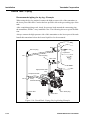
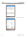
2.3.2 :Pressure Measurement - Piping
Recommended piping - Example
For gas-pressure measurement, piping should be performed following the typical
example shown here. Always observe these points:
After completing piping work, check for pressure leaks around connecting pipe and
transmitter.
Gas vent plug
Gas vent plug
Tee
Tee
Process pipe
Process pipe
Main valve
Main valve
Local valve
Local valve
Drain valve
Drain valve
Vent / Drain plug
Vent / Drain plug
GTX
D Type Transmitter
GTX
G, GTX
A Type Transmitter
Figure 2-12 Gas Pressure Measurement - Piping
Piping method
The piping method for the fluid to be measured depends on the meter installation position and the pipe line state. Typical examples of piping are shown in Figure 2-13.
Connect pipes by the following procedure:
(1) Use a T-shaped joint for the connecting pipeline.
(2) Install a main valve between the entrance of the connecting pipe and the T-shaped
joint.
(3) If the process is a horizontal line, tilt the pipe to allow draining from the pressure
line.
~Note
2-14
In case of a high pressure process, select a joint of appropriate specifications and shape and a pipe of appropriate shape and material with care.
AT9000 Advanced Transmitter
Yamatake Corporation
Installation
(4) Determine the connecting pipe schedule number and the nominal thickness of the
connecting pipe from the process based on conditions such as the process pressure.
Capacitor
Main valve
Main valve
Process
Local valve
Process
Local valve
Drain valve
A. Liquid
Drain valve
C. Moist gas
Local valve
Drain valve
Local valve
Siphon
Drain valve
Main valve
Main valve
Process
Process
B. Dry gas
D. Steam
Figure 2-13 Example of Piping
Auxiliary equipment
(1) Oil sealing and air purging
If the pressure medium (such as suspension, high viscosity, and corrosive fluid) should
not be led directly to the element, avoid it by means of sealing or purging. Various
sealing and purging methods are available. Consult us for each case.
(2) Preventing pulsations
If the process has serious pulsations or great pressure fluctuations, provide a throttle
valve in the middle of the connecting pipe to prevent pulsations.
AT9000 Advanced Transmitter
2-15
Installation
Yamatake Corporation
2.3.3 :Liquid Level Measurement - Piping (GTX_ _D/GTX_ _G)
Piping
Introduction
For measurement by GTX_ _D type of liquid level in a tank, the piping method
depends on whether the tank is open or closed. For closed tanks, piping is modified
according to whether you use the gas sealing method (dry leg) or the liquid sealing
method (wet leg).
H mark
H indicating high pressure is marked on the center body of this transmitter. Check the
mark during piping work. The low-pressure side has no mark.
Low-pressure side
High-pressure side
H
Figure 2-14 H mark on center body
Before your start
The following parts are requirements for piping work. Refer to illustration.
•
•
•
•
•
•
•
•
2-16
3-way manifold valve
Pipe
Main valve
Union or flange
Tee
Drain valve
Drain plug
Seal pot (for closed tank and wet-leg only)
AT9000 Advanced Transmitter
Yamatake Corporation
Installation
Open Tank - Piping
Recommended piping - Example
For open tanks, connect the high-pressure side of this transmitter to the lower part of
the tank. Open the low-pressure side to the air.
After completing piping work, check for pressure leaks around the connecting pipe,
the transmitter, and the 3-way manifold valve. The illustration shows a typical installation.
Connect the high-pressure side of this transmitter to the lower part of the tank.
Install this transmitter below the lowest liquid level to be measured.
Open tank
Open tank
Liquid level
Liquid level
Main valve
Main valve
3-way
manifold valve
Tee
Tee
Drain valve
Drain valve
Vent / Drain plug
Vent / Drain plug
Figure 2-15 Open Tank - Piping Example
AT9000 Advanced Transmitter
2-17
Installation
Yamatake Corporation
Closed Tank - Piping
Recommended piping for dry leg - Example
When using the dry-leg method, connect the high-pressure side of the transmitter to
the lower part of the tank. Connect the low-pressure side to the gas-sealing pipe of the
tank.
After completing piping work, check for pressure leaks around the connecting pipe,
the transmitter, and the 3-way manifold valve. The following shows a typical installation.
Always connect the high-pressure side of this transmitter to the lower part of the tank.
Install this transmitter below the lowest liquid level to be measured.
Main valve
Gas vent plug
Liquid level
Gas vent plug
Tee
Main valve
High-pressure side
Tee
Low-pressure side
Tee
3-way
manifold valve
Drain valve
Vent / Drain plug
Drain valve
Figure 2-16 Closed Tank - Piping (Dry-leg Sealing Example)
2-18
AT9000 Advanced Transmitter
Yamatake Corporation
Installation
Recommended piping for wet leg - Example
When using the wet-leg method, connect the high-pressure side of the transmitter to
the sealing pipe of the tank. Connect the low-pressure side to the lower part of the
tank.
After completing piping work, check for pressure leaks around the connecting pipe,
the transmitter, and the 3-way manifold valve. The illustration shows a typical installation.
Be sure to connect the low-pressure side of this transmitter to the lower part of the
tank.
Install this transmitter below the lowest liquid level to be measured.
Main valve
Seal pot
Liquid level
Main valve
Gas vent plug
High pressure side
Low pressure side
Drain valve
Drain valve
Vent / Drain plug
Figure 2-17 Closed Tank - Piping (Wet-leg Sealing Example)
AT9000 Advanced Transmitter
2-19
Installation
Yamatake Corporation
ATTENTION
For liquid or steam, the piping should slope a minimum of 25.4 mm (1 inch) per 305
mm (1 foot). Slope the piping down towards the transmitter if the transmitter is below
the process connection so the bubbles may rise back into the piping through the liquid.
If the transmitter is located above the process connection, the piping should rise vertically above the transmitter, then slope down towards the flowline with a vent valve at
the high point. For gas measurement, use a condensate leg and drain at the low point
(freeze protection may be required here).
2-20
AT9000 Advanced Transmitter
Yamatake Corporation
Installation
2.4 : Wiring AT9000 Advanced Transmitter
2.4.1 :Wiring for Transmitter -- Regular Model
Introduction
Following wiring instructions when no explosion-proof standards apply.
Wire and cable this transmitter as shown in the illustrations.
DC Power Supply
24V
+
Blanking plug
-
Receiving
instrument +
Earth Screw
Figure 2-18 Wiring for transmitter without Alarm output
~Note
1. External load resistance of at least 250Ω required for communications with an HART® communicator. If total load resistance of the
receiving instrument is less than 250Ω, insert the necessary resistance to the loop.
2. In using Yamatake’s field type indicator (Model NWS300, Model
NWA300), please consult us.
3. A blanking plug may not be used on the adapter or elbow.
AT9000 Advanced Transmitter
2-21
Installation
Yamatake Corporation
DC Power Supply
24V
+
-
Receiving
instrument +
This line should be connected to ground.
Earth Screw
Diode(For inductive load)
+
DC Power Supply
30V Max
30mA Max
Alarm load
Figure 2-19 Wiring for transmitter with Alarm output
~Note
Current cannot checked for a transmitter with alarm contact output.
Conduit pipe for cables
Lead cables into the transmitter case, as follows:
Mount a conduit pipe in the conduit hole (1/2NPT female thread) provided on the side
of a transmitter, and lead cables through the pipe.
Seal the part that contacts with the conduit pipe. Use a sealing agent or a seal plug to
prevent entry of water.
Install transmitter so that the cables lead into it, from the bottom.
Grounding
If a shielded cable is used, earth (ground) the shield at the receiver only (single point
ground). Connecting the shield to signal ground is recommended to make the electric
potential difference lower.
If the transmitter is not grounded through a pipe stanchion, ground the transmitter
using an earth terminal in the transmitter.
To ground the transmitter, the ground resistance must be 100Ω or lower.
2-22
AT9000 Advanced Transmitter
Yamatake Corporation
Installation
External Earthing or Bonding Connection
The connection of the earthing or equipotential bonding conductor with the external
grounding terminal must comply with the following method.
Figure 2-20 External Grounding or Bonding Connection
Supply power and external load resistance
Confirm the relationship between the external load resistance and the supply voltage.
As shown in the illustration, the relationship should be inside the shaded area.
External resistance: the total resistance connected to the output terminals of a transmitter (includes resistances of all cables in the loop plus the internal resistance of the
instruments).
The horizontal axis represents the supply voltage of a transmitter, and vertical axis
represents the external load resistance
1482
1345
Load resistance (Ω)
=
Operative limit
Load resistance (W)
Supply voltage - 12.5
0.0219
Operating Range
245
0
12.5
17.9
42 45
Supply voltage (V DC)
Figure 2-21 Supply Voltage and External Load Resistance - Relationship
~Note
1. 45 volt operation is permitted.
2. For communication with HART® communicator, a load resistance of
250 Ω or more is needed.
AT9000 Advanced Transmitter
2-23
Installation
Yamatake Corporation
Summary
For wiring the transmitter, you simply connect the positive (+) and negative (-) loop
wires to the positive (+) and negative (-) signal terminals on the terminal block in the
transmitter’s electronics housing as shown in Figure 2-22.
Electronics
Housing
Terminal
Block
Figure 2-22 AT9000 Advanced Transmitter Terminal Block.
2-24
AT9000 Advanced Transmitter
Chapter 3 :
Operation of the Transmitter
3.1 : Preparation
Instructions for connecting HART® Communicator to this transmitter.
Basic instructions for Key-pad operation.
3.1.1 :Connecting communicator
You connect the communicator directly to signal terminals on the transmitter's terminal block or at any location in the 4 to 20 mA loop. (Polarity of the communicator connection does not matter)
Figure 3-1
AT9000 Advanced Transmitter
3-1
Operation of the Transmitter
Yamatake Corporation
3.1.2 :HART® 375 FIELD COMMUNICATOR keyboard
Figure 3-2 HART® 375 FIELD COMMUNICATOR
3.1.3 :Symbols on communicator screen
See manual of 375 FIELD COMMUNICATOR.
3.1.4 :Keying in alphanumeric characters
See manual of 375 FIELD COMMUNICATOR.
3-2
AT9000 Advanced Transmitter
Yamatake Corporation
Operation of the Transmitter
3.2 : Setting and Checking Specifications
3.2.1 :Establishing Communications
This procedure starts communications between the transmitter and the communicator:
STEP
Action and/or Description
1
Turn on communicator. The communicator runs a self-test check then
determines if it is connected to a transmitter.
2
If you receive a communication error message (No Device Found),
check the following:
• Loop resistance: Is there a minimum of 250 Ω resistance between the
communicator and the power supply?
• Power supply: Is power applied? Is there greater than 11 volts at the
transmitter?
Correct any problems, and try communicating again. If the message, or
any other error message, appears again, refer to “"Chapter 6: Troubleshooting"”.
3
When the “Online” display - shown below - appears, you have established communication with the transmitter.
The flashing heart icon in the upper right corner indicates the communicator and the transmitter are communicating.
AT9000 Advanced Transmitter
3-3
Operation of the Transmitter
Yamatake Corporation
3.2.2 :Setting Tag No.
Procedure
This shows how to change or enter tag number.
(Device) - (Basic Setup) - (Tag)
After entering a tag number with pressing ENTER, press SEND to download the
change to the transmitter.
3.2.3 :Checking Output Format
Procedure
This shows how to change output format, which linear calculation or square root calculation
used for measuring differential pressure between a primary element with DP
type transmitter.
(Device) - (Basic Setup) - (Transfer Function)
3.2.4 :Checking Display Setting
Procedure
This shows how to configure display format and/or its ranges.
(Device) - (Display)
Menu items when Display Mode is%:
1 Display Mode
2 Display Function
3 Transfer Function
Menu items when Display Mode is pressure:
1 Display Mode
2 Transfer Function
Menu items when Display Mode is scale:
1 Display Mode
2 Display Function
3 Transfer Function
4 EULO (0%)
5 EUHI (100%)
6 Disp. Unit
7 User Unit
8 Exponent
3-4
AT9000 Advanced Transmitter
Yamatake Corporation
Operation of the Transmitter
3.2.5 :Display Mode
%:
pressure:
scale:
Displaying PV with%
Displaying PV with pressure unit
Displaying scaling PV
3.2.6 :Display Function
Linear:
Square root:
Displays linear.
Displays flow by square root extraction.
3.2.7 :Checking Engineering Unit of Measured Pressure
Procedure
This function is to check a pressure unit of the transmitter.
(Device) - (Display) - (Disp. Unit)
inH2O
inHg
mmH2O
psi
bar
mbar
g/Sqcm
kg/Sqcm
mmHg
Pa
kPa
MPa
3.2.8 :Checking Low and High Limits of Setting Range
Procedure
This is to configure the measuring range of the transmitter.
(Device) - (Basic Setup)
- Select Lower Ranges Value (0%) or Upper Range Value (100%) to key in the desired
setting.
- Press ENTER. This takes you back to “Basic Setup” menu.
- Press SEND to download change to transmitter.
If the number of digits you key in is more than four, the set range will not on
“Basic Setup” menu.
LRL and URL are to refer only.
AT9000 Advanced Transmitter
3-5
Operation of the Transmitter
Yamatake Corporation
3.2.9 :Adjusting Damping Time Constant
Procedure
You can adjust the damping time to reduce the output noise.
(Device) - (Signal Condition) - (Damping)
When in the PV damping menu, key in appropriate damping time from 0.0 to 128.0,
and the press ENTER. A display will prompt when you enter the value out of range
that the value is out of range.
3.2.10 :Checking Fill fluid temperature compensation
Procedure
This function implemented by inputting the height between the flanges on which the
transmitter is mounted.
(Device) - (Signal condition) - (Height)
Key in the height between the flanges in meter.
When communicating with the transmitter without this function, the screen shows
“0.00 m”.
Keying in “0” disables the function.
Sealed liquid temperature correction function
When the liquid level of a tank is measured using a remote sealing type differential
pressure transmitter, the density of the sealed liquid in the capillary tube changes as
the ambient temperature changes. This ordinarily causes about 4~5% zero shifting.
The GTXR has a composite semiconductor sensor with a function for correcting
sealed liquid temperature by means of temperature measurement and arithmetic operation with a microprocessor. This assures accurate level measurements. (The zero shift
is reduced to 1/5 from the previous level.)
Example of zero shift
L (Difference between flanges): 2500 mm (2.5 m)
R (Measurement span): 2500 mm (2.5 m)
A (Temperature coefficient of sealed liquid):0.001/°C
T (Ambient temperature change): 55°C
A×T×L
Zero shift = ---------------------- × 100 ... (1)
R
From (1)
Zero shift of a model without temperature correction:
0.001
× 55 × 2500------------------------------------------× 100 = 5.5 %
2500
(Conventional transmitter)
Zero shift of a model with temperature correction
function: 1%
3-6
AT9000 Advanced Transmitter
Yamatake Corporation
Operation of the Transmitter
3.3 : Measurement with model GTX_ _D
3.3.1 :Flow Rate Measurement
Preparation for Measurement
WARNING
•
Make sure that the process is in the manual control mode.
If in automatic control mode, switch to manual control before starting the following procedures.
• Drain poisonous fluids with care, making provisions to protect personnel.
• Always close the differential pressure output valve (main valve), the drain
valve, the gas vent plug (Refer to Figure 2-9 and Figure 2-10) and the
high pressure side and low pressure side stop valves of the 3-way manifold valve. Also, open the equalizer valve of the 3-way manifold valve.
Procedure 1
Lead process pressure into the pressure receiving part of the transmitter, using this procedure:
Step
Description
1
Gradually open the main valves of both the high-pressure side and the
low-pressure side (Refer to Figure 2-9 and Figure 2-10). Lead process
fluid into the connecting pipe.1
2
Fill with process fluid, the pressure-receiving part of the transmitter.
1. Gradually open the high pressure side stop valve. Close, after the pressure receiving part has completely filled with process fluid.
2. Gradually open the low pressure side stop valve. Close, after the pressure receiving part has completely filled with process fluid.
(Equalizer valve)
High-pressure side
Low-pressure side
side
( Low-pressure
)
stop valve
3-way manifold valve
AT9000 Advanced Transmitter
Vent / Drain plug
3-7
Operation of the Transmitter
Step
3
4
Yamatake Corporation
Description
Decrease to zero, the differential pressure applied to the transmitter.
•
Gradually open the high-pressure side stop valve to lead process pressure
into the pressure receiving part of the transmitter.
•
In this state, equal pressure is applied to the high-pressure side and the lowpressure side of the transmitter (equal pressure state).
Check for pressure leaks in the connecting pipe, the 3-way manifold valve,
and the transmitter.
Procedure 2
Perform zero-point calibration, using this procedure:
Zero point calibration by HART® communicator operation
Check that the transmitters input is 0 kPa and its output is 0% at Online display. (Refer
to "3.2.1 : Establishing Communications").
If the screen display is not 0 kPa perform zero-point calibration using this procedure.
CAUTION
If damping time constant is set to 0 sec. please adjust another value to keep the output
stable before calibration. (Refer to "3.2.9 : Adjusting Damping Time Constant")
(Device)-(Calibration) - (Correct Input)
• Select “Zero Trim”.
•
•
•
•
3-8
You will be warned to remove the loop from automatic control. After
doing so,
press OK.
When prompted, adjust pressure source to apply pressure equal to zero,
then press OK.
When pressure is stable, press OK.
AT9000 Advanced Transmitter
Yamatake Corporation
Operation of the Transmitter
Starting Measurement
Procedure 3
Apply the differential pressure of the process by operating valves, using this procedure.
How to apply process pressure
Step
Description
1
Ensure that the 3-way manifold valve is in the following state:
1. High-pressure side stop valve: Fully open
2. Low-pressure side stop valve: Fully closed
3. Equalizer valve: Fully open
2
1. Close the equalizer valve.
2. Open the low-pressure side stop valve gradually.
(Equalizer valve)
High-pressure side
Low-pressure side
side
( Low-pressure
)
stop valve
3-way manifold valve
Vent / Drain plug
CAUTION
Securely close the cover of the transmitter case. Imperfect closure allows entry of
water, and may damage internal terminals as well as the electronics module. Such
damage may require parts replacement, possibly of the entire module.
•
•
If input and output values do not match, check the range and re-calibrate.
If the displayed data value is unstable, adjust the damping time constant.
AT9000 Advanced Transmitter
3-9
Operation of the Transmitter
Yamatake Corporation
Stopping Measurement
Procedure
Stop the transmitter, using this procedure:
Step
Description
1
Turn off the transmitter
2
Operate the 3-way manifold valve by the following procedure:
1. Close the low-pressure side stop valve.
2. Open the equalizer valve.
3. Close the high-pressure side stop valve
(Equalizer valve)
High-pressure side
Low-pressure side
side
( Low-pressure
)
stop valve
3-way manifold valve
3
Vent / Drain plug
Close the main valves on the high and low pressure sides.
Refer to Figure 3-9 and Figure 3-10.
CAUTION
•
•
3-10
If you plan to leave the transmitter OFF for a long period of time, always
drain process fluid from the connecting pipe and the pressure-receiving
part.
Leave the equalizer valve open.
AT9000 Advanced Transmitter
Yamatake Corporation
Operation of the Transmitter
3.3.2 :Gas Pressure Measurement
Preparation for Measurement
WARNING
•
•
•
Ensure that the process is in the manual control mode.
If the process is in automatic control mode, switch to manual before starting the
procedure.
Drain poisonous fluids with care, making provisions to protect personnel.
Close the differential pressure output valve (main valve), the local valve,
the drain valve, and the gas vent plug. Refer to "Figure 2-12 Gas Pressure Measurement - Piping".
How to measure gas pressure
Perform zero-point adjustment and introduce process pressure into the transmitter,
using this procedure:
• Zero-point adjustment
Step
Description
1
Open both the high-pressure side and low-pressure side vent plugs and
open the pressure receiving part to the air.
2
Refer to procedure 2 on page 3-8. Perform zero-point calibration.
3
After completing zero-point calibration, close the high-pressure side vent
plug.
AT9000 Advanced Transmitter
3-11
Operation of the Transmitter
Yamatake Corporation
Introducing process pressure and venting air
Step
Description
1
1. Open the main valve (refer to "Figure 2-12 Gas Pressure Measurement
- Piping".) to introduce process pressure into the connecting pipe.
2. Open the local valve gradually, to introduce process pressure into the
pressure-receiving part of the transmitter.
2
1. Open the high-pressure side vent plug gradually, to vent air from the
center body.
2. After venting air, close the vent plug and the local valve.
Local valve
High-pressure side
Vent / Drain plug
3
3-12
Check for pressure leaks in the connecting pipe and the transmitter.
AT9000 Advanced Transmitter
Yamatake Corporation
Operation of the Transmitter
Starting Measurement
Procedure
Operate the valves using this procedure, to apply process pressure to the transmitter.
• How to apply process pressure
Step
1
Description
Open the local valve gradually.
Local valve
High-pressure side
Vent / Drain plug
CAUTION
Securely close the cover of the transmitter case. Failure to do so will result in entry of
water, and cause damage to internal terminals and the electronics module.
•
•
If input and output values fail to match, check the range and re-calibrate.
If the displayed data value is unstable, adjust the damping time constant.
AT9000 Advanced Transmitter
3-13
Operation of the Transmitter
Yamatake Corporation
Stopping Measurement
Procedure
How to stop the transmitter
Step
Description
1
Turn off the transmitter.
2
Close the local valve.
Local valve
High-pressure side
Vent / Drain plug
3
Close the main valve. (Refer to "Figure 2-12 Gas Pressure Measurement Piping".)
CAUTION
If you plan to leave the transmitter OFF for a long period of time, completely drain
process fluid from the connecting pipe, and from the pressure receiving part.
3-14
AT9000 Advanced Transmitter
Yamatake Corporation
Operation of the Transmitter
3.3.3 :Liquid Level Measurement of Open Tank and Closed Tank (Dry
Leg)
Preparation for Measurement
WARNING
•
Place the process in the manual control mode.
If the process is in the automatic control mode, switch to manual before performing
work.
• Drain poisonous fluids carefully, taking provisions to protect workers.
• Check that the differential pressure output valve (main valve), the drain
valve, the gas vent plug (refer to "Figure 2-15 Open Tank - Piping Example".) are closed, as well as the high pressure side and low pressure side
stop valves of the 3-way manifold valve. Also, make sure that the equalizer valve of the 3-way manifold valve is open.
Calculating setting range
Calculate the setting range. Refer to "3.8 : Set Range Calculation for Liquid Level
Measurement".
Procedure
Perform zero-point adjustment and introduce process pressure into the transmitter by
this procedure:
Zero-point calibration
Step
Description
1
Open the drain plugs and the stop valves of both the high-pressure side
and the low-pressure side. Open the pressure receiving part to the air.
If fluid remains in the pressure receiving part, blow it to drain.
2
Refer to procedure 2 in page 3-8 and perform zero-point calibration.
3
After completing zero-point calibration, close the high-pressure side drain
plug and the high-pressure side stop valve.
AT9000 Advanced Transmitter
3-15
Operation of the Transmitter
Yamatake Corporation
Introducing process pressure
Step
Description
1
1. Open the main valve (refer to"Figure 2-15 Open Tank - Piping Example") to introduce process pressure into the connecting pipe.
2. Open the high-pressure side stop valve gradually to introduce process
pressure. After introducing process pressure into the pressure receiving
part of the transmitter, close the high-pressure side stop valve.
(Equalizer valve)
High-pressure side
Low-pressure side
side
( Low-pressure
)
stop valve
3-way manifold valve
2
3-16
Vent / Drain plug
Check for pressure leaks in the connecting pipe, the 3-way manifold
valve, and the transmitter.
AT9000 Advanced Transmitter
Yamatake Corporation
Operation of the Transmitter
Starting Measurement
Procedure
Operate the valves with this procedure, to apply the differential pressure of the process
to the transmitter.
How to apply process pressure
Step
1
Description
Check that the 3-way manifold valve is in the following state:
1. High-pressure side stop valve: Fully closed
2. Low-pressure side stop valve: Fully open
3. Equalizer valve: Fully closed
(Equalizer valve)
High-pressure side
Low-pressure side
side
( Low-pressure
)
stop valve
3-way manifold valve
2
Vent / Drain plug
1. Open the high-pressure side stop valve gradually.
CAUTION
Securely close the cover of the transmitter case. Failure to do so will result in entry of
water, and cause damage to internal terminals and the electronics module.
•
•
If the input and output values do not match, check the range and re-calibrate.
If the displayed data value is unstable, adjust the damping time constant.
AT9000 Advanced Transmitter
3-17
Operation of the Transmitter
Yamatake Corporation
Stopping Measurement
Procedure
How to stop the transmitter
Step
Description
1
Turn off the transmitter.
2
Operate the 3-way manifold valve using this procedure:
1. Close the low-pressure side stop valve.
2. Open the equalizer valve.
3. Close the high-pressure side stop valve.
(Equalizer valve)
High-pressure side
Low-pressure side
side
( Low-pressure
)
stop valve
3-way manifold valve
3
Vent / Drain plug
Close the main valve. Refer to "Figure 2-15 Open Tank - Piping Example".
CAUTION
3-18
•
If you plan to leave the transmitter OFF for a long period, drain process
fluid from the connecting pipe and the pressure receiving part.
•
Leave the equalizer valve open.
AT9000 Advanced Transmitter
Yamatake Corporation
Operation of the Transmitter
3.3.4 :Liquid Level Measurement of Closed Tank (Wet Leg)
Preparation for Measurement
WARNING
•
•
•
Place the process in manual control mode.
If the process is in automatic control mode, change it to the manual control mode
before performing this work.
Drain poisonous fluids with care, making provisions for protecting workers.
Make sure that the differential pressure output valve (main valve), the
drain valve, the gas vent plug (refer to "Figure 2-17 Closed Tank - Piping
(Wet-leg Sealing Example)".) and the high pressure side and low pressure
side stop valves of the 3-way manifold valve are closed. Also, make sure
that the equalizer valve of the 3-way manifold valve is open.
Calculating setting range
For the procedure for obtaining the setting range by calculation, refer to "3.8 : Set
Range Calculation for Liquid Level Measurement".
Procedure
Perform zero-point adjustment and introduce process pressure into the transmitter
using this procedure:
Zero-point calibration
Step
Description
1
Feed sealing liquid from the seal pot to fill the connecting pipe with sealing liquid.
2
Gradually open the stop valves of both the high-pressure side and the lowpressure side, and the drain plugs, to fill the pressure receiving part of the
transmitter with sealing liquid.
3
When sealing liquid flows out from the drain plugs, close the stop valves
of both the high pressure side and the low pressure side and the drain
plugs.
In this state, the same pressure is applied to the high pressure side and the
low pressure side of the transmitter (equal pressure state).
4
Referring to procedure 2 in page 3-8, perform zero point calibration.
5
After completing zero-point calibration, close the equalizer valve. Open
the stop valve and the drain plug of the low-pressure side to drain sealing
liquid. Close the stop valve and the drain plug of the low-pressure side.
AT9000 Advanced Transmitter
3-19
Operation of the Transmitter
Yamatake Corporation
(Equalizer valve)
High-pressure side
Low-pressure side
side
( Low-pressure
)
stop valve
3-way manifold valve
Vent / Drain plug
Introducing process pressure
Step
3-20
Description
1
Open the main valve (Refer to "Figure 2-17 Closed Tank - Piping (Wetleg Sealing Example)".) to introduce process fluid into the connecting
pipe.
2
Gradually open the low pressure side stop valve to introduce process fluid.
After introducing process fluid into the pressure receiving part of the
transmitter, close the low pressure side stop valve.
3
Make sure that the connecting pipe, the 3-way manifold valve, and the
transmitter have no pressure leaks.
AT9000 Advanced Transmitter
Yamatake Corporation
Operation of the Transmitter
Starting Measurement
Procedure
Operate the valves by the following procedure to apply the differential pressure of the
process to the transmitter and display the measured value by operating the HART®
communicator.
How to apply process pressure
Step
Description
1
Make sure that the 3-way manifold valve is in this state:
1. High-pressure side stop valve: Fully closed
2. Low-pressure side stop valve: Fully closed
3. Equalizer valve: Fully closed
2
Fill the liquid sealing pipe with sealing liquid.
3
1. Gradually open the high-pressure side stop valve.
2. Gradually open the low-pressure side stop valve.
(Equalizer valve)
High-pressure side
Low-pressure side
side
( Low-pressure
)
stop valve
3-way manifold valve
Vent / Drain plug
CAUTION
Close the cover of the transmitter case securely. Imperfect closure allows entry of
water, damaging internal terminals and the electronics module.
•
•
If the input and output values are inconsistent, check the range and perform calibration again.
If the displayed data value is unstable, adjust the damping time constant.
AT9000 Advanced Transmitter
3-21
Operation of the Transmitter
Yamatake Corporation
Stopping Measurement
Procedure
How to stop the transmitter
Step
Description
1
Turn off the transmitter.
2
Operate the 3-way manifold valve by the following procedure:
1. Close the low pressure side stop valve.
2. Open the equalizer valve.
3. Close the high pressure side stop valve.
(Equalizer valve)
High-pressure side
Low-pressure side
side
( Low-pressure
)
stop valve
3-way manifold valve
3
Vent / Drain plug
Close the main valve. (Refer to Figure 2-17.)
CAUTION
•
•
3-22
If the transmitter is to be left off for a long period of time, drain process
fluid from the connecting pipe and the pressure receiving part.
Leave the equalizer valve open.
AT9000 Advanced Transmitter
Yamatake Corporation
Operation of the Transmitter
3.4 : Measurement with Model GTX_ _D/GTX_ _A
3.4.1 :Pressure Measurement
Preparation for Measurement
WARNING
•
Make sure that the process is in the manual control mode.
If the process is in the automatic control mode, switch it to manual mode.
• For hazardous fluids (poisons etc.) take any necessary actions to prevent
physical hazard and ensure that work proceeds with adequate care.
• Before starting a measurement procedure, ensure closure of the pressure
valve (main valve), the local valve, the drain valve, and the gas vent plug
(Refer to Figure 2-12).
Gas pressure measurement
Perform zero-point calibration and introduce process pressure, with this procedure:
CAUTION
If damping time constant is set to 0 sec., please adjust another value to keep output stable before calibration.
Zero-point calibration
Step
Description
1
Open the vent plug to release the pressure receiving part to the open air.
2
Referring to procedure2 in page 3-8, perform zero-point calibration.
3
When calibration is complete, close the vent plug.
AT9000 Advanced Transmitter
3-23
Operation of the Transmitter
Yamatake Corporation
Introducing process pressure and venting air
Step
Description
1
1. Introduce the process pressure into the connecting pipe by opening the
main valve (Refer to "Figure 2-13 Example of Piping"). If the process
temperature is high, allow cooling time so that the connecting pipe is stable at a safe temperature, before starting work.
2. Open the local valve gradually to introduce the process pressure into the
pressure receiving part of transmitter.
2
1. Vent air from the center body by gradually opening the vent plug.
2. After venting air completely, close the plug and the local valve.
Local valve
High-pressure side
Vent / Drain plug
3
3-24
Ensure zero leakage exists at the connecting pipe and transmitter.
AT9000 Advanced Transmitter
Yamatake Corporation
Operation of the Transmitter
Starting Measurement
Procedure
Operate the valve with the following procedure and apply the process pressure to
transmitter.
Step
1
Description
Open gradually the local valve.
Local valve
High-pressure side
Vent / Drain plug
CAUTION
Securely close the case cover of the transmitter. Take precautions against moisture
ingress into the transmitter body. Water entering the transmitter will damage the internal terminals and the electronics module.
•
•
If the output value does not correctly reflect the input value, check again
the range and calibrate the transmitter.
If the displayed data value is unstable, adjust the damping time constant
AT9000 Advanced Transmitter
3-25
Operation of the Transmitter
Yamatake Corporation
Stopping Measurement
Procedure
Stop the operation of the transmitter by this procedure:
Step
Description
1
Turn OFF the transmitter.
2
Close the local valve.
Local valve
High-pressure side
Vent / Drain plug
3
Close the main valve.
CAUTION
When a long-term shutdown is planned, completely drain all process fluid from the
connecting pipe and from the pressure receiving part of transmitter.
3-26
AT9000 Advanced Transmitter
Yamatake Corporation
Operation of the Transmitter
3.5 : Measurement with Model GTX_ _F
3.5.1 :Pressure Measurement
Preparation for Measurement
When setting the zero point, set all the diaphragm surface area to be wet with the measured liquid for high accuracy. Even when the diaphragm surface area is not completely wet, make sure that the zero point is set at a level higher than the center of the
diaphragm.
100 % Liquid Level
Variable
Head
0 % Liquid Level
Figure 3-3
AT9000 Advanced Transmitter
3-27
Operation of the Transmitter
Yamatake Corporation
Starting Measurement
The transmitter is ready for operation when zero-point adjustment is completed. This
procedure is described in the previous section. Before starting, always check the following:
(1) Check the correspondence between input and output values.
•
If the output does not correctly reflect the input, check the range, check
the flange position on the process, and calibrate the transmitter again.
(2) Check the displayed data.
• If unstable value is displayed, adjust the damping time constant.
(3) Perform the following items carefully:
•
•
•
Disconnect the HART® communicator from the transmitter terminal.
Ensure that the terminal is sufficiently tight, and not loose.
Close the case cover. Screw in the cover firmly until it can no longer be
turned.
This transmitter has a locking structure. After closing the cover, tighten
the lock using a hexagon wrench.
Stopping Measurement
Procedure
Turn off the transmitter.
CAUTION
When a long-term shutdown is planned, completely drain all process fluid from the
connecting pipe and from the pressure receiving part of transmitter.
3-28
AT9000 Advanced Transmitter
Yamatake Corporation
Operation of the Transmitter
3.6 : Measurement with Model GTX_ _U/GTX_ _R
When starting operation, adjust the transmitter in its actual process state. The specific
gravity of the sealed-in liquid is stated in the specifications in Appendix A. Specific
gravity changes with temperature at the rate of 0.0008/°C. Use the temperature of the
capillary tube for items related to specific gravity, in this section.
3.6.1 :Pressure Measurement
Preparation for Measurement
When setting the zero point, set all the diaphragm surface area to be wet with the measured liquid for high accuracy. Even when the diaphragm surface area is not completely wet, make sure that the zero point is set at a level higher than the center of the
diaphragm.
100 % Liquid Level
Fixed
Ref Leg
Variable
Head
0 % Liquid Level
Figure 3-4
AT9000 Advanced Transmitter
3-29
Operation of the Transmitter
Yamatake Corporation
Starting Measurement
The transmitter is ready for operation when zero-point adjustment is completed. This
procedure is described in the previous section. Before starting, always check the following:
(1) Check the correspondence between input and output values.
•
If the output does not correctly reflect the input, check the range, check
the flange position on the process, and calibrate the transmitter again.
(2) Check the displayed data.
• If unstable value is displayed, adjust the damping time constant.
(3) Perform the following items carefully:
•
•
•
Disconnect the HART® communicator from the transmitter terminal.
Ensure that the terminal is sufficiently tight, and not loose.
Close the case cover. Screw in the cover firmly until it can no longer be
turned.
This transmitter has a locking structure. After closing the cover, tighten
the lock using a hexagon wrench.
Stopping Measurement
Procedure
Turn OFF the transmitter.
CAUTION
When long-term shutdown is planned, always dismount the transmitter flange from the
tank, clean diaphragms with a soft brush, wash using a solvent, and store. Take care
not to deform or damage the diaphragms.
3.6.2 :Cautions Related to Flow Rate Measurement
Refer to the instructions on flange mounting for flow-rate measurement, to operate the
transmitter for flow rate measurement.
Always complete zero-point checking before introducing fluid to the pipe. This precaution is warranted since the GTX_ _R/GTX_ _U has a structural characteristic that
prevents mounting of an equalizing valve or stop valve.
For vertical pipes with differential-pressure take-out flange port, the high-pressure
side flange and the low-pressure side flange exhibit a level difference. In this case,
determine the zero point by setting LRV.
3-30
AT9000 Advanced Transmitter
Yamatake Corporation
Operation of the Transmitter
3.7 : Measurement with Model GTX_ _U
When starting operation, adjust the transmitter in its actual process state. The specific
gravity of the sealed-in liquid is stated in the specifications of Chapter3. Specific gravity changes with temperature at the rate of 0.0008/°C. Use the temperature of the capillary tube for items related to specific gravity, in this section.
3.7.1 :Pressure Measurement
Preparation for Measurement
When setting the zero point, set all the diaphragm surface area to be wet with the measured liquid for high accuracy. Even when the diaphragm surface area is not completely wet, make sure that the zero point is set at a level higher than the center of the
diaphragm.
100 % Liquid Level
Variable
Head
0 % Liquid Level
Figure 3-5
AT9000 Advanced Transmitter
3-31
Operation of the Transmitter
Yamatake Corporation
Starting Measurement
The transmitter is ready for operation when zero-point adjustment is completed. This
procedure is described in the previous section. Before starting, always check the following:
(1) Check the correspondence between input and output values.
•
If the output does not correctly reflect the input, check the range, check
the flange position on the process, and calibrate the transmitter again.
(2) Check the displayed data.
• If unstable value is displayed, adjust the damping time constant.
(3) Perform the following items carefully:
•
•
•
Disconnect the HART® communicator from the transmitter terminal.
Ensure that the terminal is sufficiently tight, and not loose.
Close the case cover. Screw in the cover firmly until it can no longer be
turned.
This transmitter has a locking structure. After closing the cover, tighten
the lock using a hexagon wrench.
Stopping Measurement
Procedure
Turn OFF the transmitter.
CAUTION
When long-term shutdown is planned, always dismount the transmitter flange from the
tank, clean diaphragms with a soft brush, wash using a solvent, and store. Take care
not to deform or damage the diaphragms.
3-32
AT9000 Advanced Transmitter
Yamatake Corporation
Operation of the Transmitter
3.8 : Set Range Calculation for Liquid Level Measurement
3.8.1 :Open Tank or Closed Tank (Dry Leg) or Remote Seal Set Range
Calculation
Set range calculation Ex. Model GTX_ _D
Calculate the set range using these procedures:
The following symbols are used to express density and distance.
It is assumed that the density is fixed, during liquid level measurement.
ρ : Specific gravity of liquid in tank
ρ 0 : Specific gravity of liquid in high pressure side connecting pipe
l : Distance between 100% liquid level and 0% liquid level (measurement range)
h : Distance between 0% liquid level and high-pressure outlet port
d : Distance between high-pressure outlet port and transmitter
100% liquid level
100% liquid level
High-pressure outlet port
h
ρo
l
0% liquid level
High-pressure
outlet port
ρo
Open tank
ρ
d
Low-pressure side
0% liquid level
h
ρ
d
l
Closed tank
High-pressure side
Low-pressure side
Figure 3-6 Open Tank
High-pressure side
Figure 3-7 Closed Tank
Differential pressure at 0% liquid level (Pressure on high-pressure side - Pressure on
low-pressure side) = h ρ + d ρ 0 = LRV
Differential pressure at 100% liquid level (Pressure on high-pressure side - Pressure on
low-pressure side) = l ρ + h ρ + d ρ 0 = (l+h) ρ + d ρ 0 = URV
Therefore, set the range as follows:
Low limit (LRV): h ρ + d ρ 0 ; High limit (URV): (l+h) ρ +d ρ 0
Example of calculation: l = 1500 mm, h = 250 mm, d = 500 mm ρ = 0.9, ρ 0 = 1.0
If the above conditions are assumed, the following results are obtained:
Differential pressure at 0% liquid level = (250 x 0.9) + (500 x 1.0) = 725 mmH2O =
7.110 kPa
Differential pressure at 100% liquid level = {(1500 + 250) x 0.9) + (500 x 1.0) = 2075
mmH2O = 20.35 kPa
Therefore, set the range as follows:
Low limit (LRV): 7.110 kPa{725 mmH2O}, High limit (URV): 20.35 kPa{2075
mmH2O}
AT9000 Advanced Transmitter
3-33
Operation of the Transmitter
Yamatake Corporation
Set range calculation Ex. Model GTX_ _G
Calculate the set range using these procedures:
The following symbols are used to express density and distance.
It is assumed that the density is fixed, during liquid level measurement.
ρ
ρ0
l
h
d
:Specific gravity of liquid in tank
:Specific gravity of liquid in connecting pipe
:Distance between 100% liquid level and 0% liquid level (measurement range)
:Distance between 0% liquid level and high-pressure outlet port
:Distance between high-pressure outlet port and transmitter
100% liquid level
High-pressure outlet port
h
l
0% liquid level
ρo
ρ
Open tank
d
Figure 3-8
Pressure at 0% liquid level = h ρ + d ρ 0 = LRV
Pressure at 100% liquid level = l ρ + h ρ + d ρ 0 = (l+h)r+ d ρ 0 = URV
Therefore, set the range as follows:
Low limit (LRV): h ρ + d ρ 0 ; High limit (URV): (l+h) ρ + d ρ 0
Example of calculation:
l = 1500 mm, h = 250 mm, d = 500 mm
ρ = 0.9, ρ 0 = 1.0
If the above conditions are assumed, the following results are obtained:
Differential pressure at 0% liquid level = (250 x 0.9) + (500 x 1.0) = 725 mmH2O =
7.110 kPa
Differential pressure at 100% liquid level = {(1500 + 250) x 0.9) + (500 x 1.0) = 2075
mmH2O = 20.35 kPa
Therefore, set the range as follows:
Low limit (LRV): 7.110 kPa{725 mmH2O}, High limit (URV): 20.35 kPa{2075
mmH2O}
3-34
AT9000 Advanced Transmitter
Yamatake Corporation
Operation of the Transmitter
Set range calculation Ex. Model GTX_ _F
Calculate the set range using these procedures:
The following symbols are used to express density and distance.
It is assumed that the density is fixed, during liquid level measurement.
ρ
l
h
d
: Specific gravity of liquid in tank
: Distance between 100% liquid level and 0% liquid level (measurement range)
: Distance between 0% liquid level and high-pressure outlet port
: Distance between high-pressure outlet port and transmitter
Blow valve
Open to air
l
0% liquid level
h
ρ
Figure 3-9 Open Tank
Stop valve
Tank
l
P
Volume container
100% liquid level
100% liquid level
Tank
0% liquid level
h
ρ
Figure 3-10 Closed Tank
Differential pressure at 0% liquid level (Pressure on high-pressure side - Pressure on
low-pressure side) = h ρ = LRV
Differential pressure at 100% liquid level (Pressure on high-pressure side - Pressure
on low-pressure side) = l ρ + h ρ = (l+h) ρ = URV
Therefore, set the range as follows:
Low limit (LRV): h ρ ; High limit (URV): (l+h) r
Example of calculation:
l = 1500 mm, h = 250 mm
ρ = 0.9, ρ 0 = 1.0
If the above conditions are assumed, the following results are obtained:
Differential pressure at 0% liquid level = (250 x 0.9) = 725 mmH2O = 7.110 kPa
Differential pressure at 100% liquid level = {(1500 + 250) x 0.9) = 2075 mmH2O =
20.35 kPa
Therefore, set the range as follows:
Low limit (LRV): 7.110 kPa{725 mmH2O}, High limit (URV): 20.35 kPa{2075
mmH2O}
AT9000 Advanced Transmitter
3-35
Operation of the Transmitter
Yamatake Corporation
Set range calculation Ex. Model GTX_ _R
Calculate the set range using these procedures:
The following symbols are used to express density and distance.
It is assumed that the density is fixed, during liquid level measurement.
ρ
ρ0
l
h
d
: Specific gravity of liquid in tank
: Specific gravity of sealed liquid
: Distance between 100% liquid level and 0% liquid level (measurement range)
: Distance between 0% liquid level and high-pressure outlet port
: Distance between high-pressure outlet port and transmitter
100% liquid level
Open tank
l
0% liquid level
h
d
ρ0
Low-pressure
side
High-pressure
side
ρ
Figure 3-11 Open Tank
Differential pressure at 0% liquid level (Pressure on high-pressure side - Pressure on
low-pressure side) = hr = LRV
Differential pressure at 100% liquid level (Pressure on high-pressure side - Pressure
on low-pressure side) = l ρ + h ρ = (l+h) ρ = URV
Therefore, set the range as follows:
Low limit (LRV): h ρ ; High limit (URV): (l+h) r
Example of calculation:
l = 1500 mm, h = 250 mm, d = 500 mm, ρ = 0.9, ρ 0 = 0.935
If the above conditions are assumed, the following results are obtained:
Differential pressure at 0% liquid level = 250 x 0.9= 225 mmH2O = 2.206 kPa
Differential pressure at 100% liquid level = (1500 + 250) x 0.9 = 1575 mmH2O =
15.45 kPa
Therefore, set the range as follows:
Low limit (LRV): 2.206 kPa, High limit (URV): 15.45 kPa
3-36
AT9000 Advanced Transmitter
Yamatake Corporation
Operation of the Transmitter
Set range calculation Ex. Model GTX_ _U
Calculate the set range using these procedures:
The following symbols are used to express density and distance.
It is assumed that the density is fixed, during liquid level measurement.
ρ
ρ0
l
h
d
: Specific gravity of liquid in tank
: Specific gravity of sealed liquid
: Distance between 100% liquid level and 0% liquid level (measurement range)
: Distance between 0% liquid level and high-pressure outlet port
: Distance between high-pressure outlet port and transmitter
100% liquid level
Open tank
l
0% liquid level
h
d
ρ0
Process
connection
ρ
Figure 3-12 Open Tank
Differential pressure at 0% liquid level = h ρ + d ρ 0 = LRV
Differential pressure at 100% liquid level = l ρ + h ρ + d ρ 0 = (l+h) ρ + d ρ 0 = URV
Therefore, set the range as follows:
Low limit (LRV): h ρ + d ρ 0 ; High limit (URV): (l+h) ρ + d ρ 0
Example of calculation:
l = 1500 mm, h = 250 mm, d = 500 mm, ρ = 0.9, ρ 0 = 1.0
If the above conditions are assumed, the following results are obtained:
Differential pressure at 0% liquid level = (250 x 0.9) + (500 x 1.0) = 725 mmH2O =
7.110 kPa
Differential pressure at 100% liquid level = {(1500 + 250) x 0.9) + (500 x 1.0) = 2075
mmH2O = 20.35 kPa
Therefore, set the range as follows:
Low limit (LRV): 7.110 kPa, High limit (URV): 20.35 kPa
AT9000 Advanced Transmitter
3-37
Operation of the Transmitter
Yamatake Corporation
3.8.2 :Closed Tank (Wet Leg or Remote Seal) -- Set Range
Set range calculation Ex. Model GTX_ _D
Calculate the set range using these procedure:
The following symbols are used to express density and distance.
It is assumed that the density is fixed during liquid level measurement.
ρ
ρ0
l
h
d
: Specific gravity of liquid in tank
: Specific gravity of sealing liquid
: Distance between 100% liquid level and 0% liquid level (measurement range)
: Distance between 0% liquid level and high-pressure outlet port
: Distance between high-pressure outlet port and transmitter
High-pressure outlet port
100% liquid level
l
d
0% liquid level
ρ
Low-pressure outlet port
Closed tank
h
ρ0
Closed tank
(Wet leg)
Low-pressure side
High-pressure side
Figure 3-13 Closed Tank (Wet Leg)
Differential pressure at 0% liquid level (Pressure on high-pressure side - Pressure on
low-pressure side) = d ρ 0 - h r = LRV
Differential pressure at 100% liquid level (Pressure on high-pressure side - Pressure
on low-pressure side) = d ρ 0 - (l+h) ρ = URV
Therefore, set the range as follows:
Low limit (LRV): d ρ 0 - h ρ r, High limit (URV): d ρ 0 - (l+h) ρ
Example of calculation:
l = 1500 mm, h = 250 mm, d = 2000 mm, ρ = 0.9, ρ 0 = 1.0
If the above conditions are assumed, the following results are obtained:
Differential pressure at 0% liquid level = (2000 x 1.0) + (250 x 0.9) = 1775 mmH2O =
17.41 kPa
Differential pressure at 100% liquid level = (2000 x 1.0) + (1500 x 250) x 0.9 = 425
mmH2O = 4.168 kPa
Therefore, set the range as follows:
Low limit (LRV): 17.41 kPa{1775 mmH2O}, High limit (URV): 4.168 kPa {425
mmH2O}
3-38
AT9000 Advanced Transmitter
Yamatake Corporation
Operation of the Transmitter
Set range calculation Ex. Model GTX_ _F
Calculate the set range using these procedure:
The following symbols are used to express density and distance.
It is assumed that the density is fixed during liquid level measurement.
ρ
ρ0
l
h
d
: Specific gravity of liquid in tank
: Specific gravity of sealing liquid
: Distance between 100% liquid level and 0% liquid level (measurement range)
: Distance between 0% liquid level and high-pressure outlet port
: Distance between high-pressure outlet port and transmitter
Blow valve
l
ρ0
Stop valve
d
P
100% liquid level
Tank
0% liquid level
h
ρ
Figure 3-14 Closed Tank (Wet Leg)
Differential pressure at 0% liquid level (Pressure on high-pressure side - Pressure on
low-pressure side) = d ρ 0 - h ρ = LRV
Differential pressure at 100% liquid level (Pressure on high-pressure side - Pressure on
low-pressure side) = d ρ 0 - (l+h) ρ = URV
Therefore, set the range as follows:
Low limit (LRV): d ρ 0 - h ρ , High limit (URV): d ρ 0 - (l+h) ρ
Example of calculation:
l = 1500 mm, h = 250 mm, d = 2000 mm, ρ = 0.9, ρ 0 = 1.0
If the above conditions are assumed, the following results are obtained:
Differential pressure at 0% liquid level = (2000 x 1.0) + (250 x 0.9) = 1775 mmH2O =
17.41 kPa
Differential pressure at 100% liquid level = (2000 x 1.0) + (1500 x 250) x 0.9 = 425
mmH2O = 4.168 kPa
Therefore, set the range as follows:
Low limit (LRV): 17.41 kPa{1775 mmH2O}, High limit (URV): 4.168 kPa {425
mmH2O}
AT9000 Advanced Transmitter
3-39
Operation of the Transmitter
Yamatake Corporation
Set range calculation Ex. Model GTX_ _R
Calculate the set range using these procedure:
The following symbols are used to express density and distance.
It is assumed that the density is fixed during liquid level measurement.
ρ
ρ0
l
h
d
: Specific gravity of liquid in tank
: Specific gravity of sealed liquid
: Distance between 100% liquid level and 0% liquid level (measurement range)
: Distance between 0% liquid level and lower flange of tank
: Distance between upper flange of tank and lower flange of tank
100% liquid level
d
l
Closed tank
0% liquid level
h
ρ
ρ0
Figure 3-15 Closed Tank (Wet Leg)
Differential pressure at 0% liquid level (Pressure on high-pressure side - Pressure on
low-pressure side) = d ρ 0 - h ρ = LRV
Differential pressure at 100% liquid level (Pressure on high-pressure side - Pressure
on low-pressure side) = d ρ 0 - (l+h) ρ = URV
Therefore, set the range as follows:
Low limit (LRV): d ρ 0 - h ρ , High limit (URV): d ρ 0 - (l+h) ρ
Example of calculation:
l = 1500 mm, h = 250 mm, d = 2000 mm, ρ = 0.9, ρ 0 = 0.935
If the above conditions are assumed, the following results are obtained:
Differential pressure at 0% liquid level = (2000 x 0.935) - (250 x 0.9) = 1645 mmH2O
= 16.13 kPa
Differential pressure at 100% liquid level = (2000 x 0.935) + (1500 x 250) x 0.9 = 295
mmH2O = 2.893 kPa
Therefore, set the range as follows:
Low limit (LRV): 16.13 kPa{1645 mmH2O}, High limit (URV): 2.893 kPa {295
mmH2O}
3-40
AT9000 Advanced Transmitter
Yamatake Corporation
Operation of the Transmitter
3.9 : Indicator (Optional)
3.9.1 :Display unit of indicator
The display unit of an indicator consists of the following:
1
2
5
4
11
7
12
6
13
8
9
10
3
Figure 3-16 Display unit of indicator
No.
Display Mark
Contents of display
1
Digital Display (5digits)
PV (%, actual, pressure) Status Number
2
Digital Display (5digits)
Decimal point
3
16 segments (7digit)
Unit, Status
4
%
%
5
Exponent
None, ×10, ×100, ×1000
6
Absolute pressure
Abs
7
Gage pressure
G
8
Bar Graph
Bar Graph of output%
9
Output square root extraction
OUT
10
Display square root extraction
DISP
11
Key mark
Write Protect
12
Flag mark
Status Record
13
Status Record
AT9000 Advanced Transmitter
and
3-41
Operation of the Transmitter
Yamatake Corporation
3.9.2 :Bar Graph Display
Percentage terms of the indicated values are displayed as graphs with the 22 segments.
S0 S1 S2 - - - - - - - - - - - -- - - - - - - - - - - - - - - - - - - - - - - - - - - - S20
For descriptive purposes let us refer to the 22 segments as, from left to right, S0 - S21.
Lighting or blinking of each segment is indicated as follows according to the percentage terms of the indicated value (DISP).
-5%
0%
5%
10%
15%
20%
25%
30%
35%
40%
45%
50%
55%
60%
65%
70%
75%
80%
85%
90%
95%
100%
105%
<
<
<
<
<
<
<
<
<
<
<
<
<
<
<
<
<
<
<
<
<
<
<
DISP < -5%
DISP < 0%
DISP < 5%
DISP < 10%
DISP < 15%
DISP < 20%
DISP < 25%
DISP < 30%
DISP < 35%
DISP < 40%
DISP < 45%
DISP < 50%
DISP < 55%
DISP < 60%
DISP < 65%
DISP < 70%
DISP < 75%
DISP < 80%
DISP < 85%
DISP < 90%
DISP < 95%
DISP <100%
DISP <105%
DISP
S0 Blinking
S0 Lit
S0 to S1 Lit
S0 to S2 Lit
S0 to S3 Lit
S0 to S4 Lit
S0 to S5 Lit
S0 to S6 Lit
S0 to S7 Lit
S0 to S8 Lit
S0 to S9 Lit
S0 to S10 Lit
S0 to S11 Lit
S0 to S12 Lit
S0 to S13 Lit
S0 to S14 Lit
S0 to S15 Lit
S0 to S16 Lit
S0 to S17 Lit
S0 to S18 Lit
S0 to S19 Lit
S0 to S20 Lit
S0 to S21 Lit
S0 to S20 Lit, S21Blinking
3.9.3 :External Zero/Span Adjustment Display
When an external zero or span adjustment is executed using an external zero/span
adjustment mechanism and the range change is complete, one of the following messages is displayed in the 16 segments (7 digits) that display the unit, depending on the
adjustment.
When an external zero adjustment is complete: ZERO.SET
When an external span adjustment is complete: SPAN.SET
The message is displayed for 3 seconds and then it disappears to return to the unit display.
3-42
AT9000 Advanced Transmitter
Yamatake Corporation
Operation of the Transmitter
3.9.4 :Square Root Extraction Display
The segments for the square root extraction display are OUT
and DISP
.
Each display lights up or goes out according to the output format and square root extraction display settings of the transmitter.
Transmitter setting
Square Root Extraction Display
Output
Indicator
OUT
DISP
Linear
Linear
Goes out
Goes out
Linear
Square root (Flow rate)
Goes out
Lights up
Lights up
Goes out
Square root (Flow rate)
3.9.5 :Write Protect Display
The indicator for the write protect display is a key mark.
The key mark lights up or goes out according to the write protect state of the transmitter.
When write protect is ON: The key mark lights up.
When write protect is OFF: The key mark goes out.
3.9.6 :Status Record Display
The indicator for the status history display is a flag mark.
The flag mark lights up or goes out according to the presence or absence of status history
of the transmitter.
When the status history exists: The flag mark lights up.
When the status history does not exist: The flag mark goes out.
Lighting of the flag mark indicates that the diagnostic status has been ON in the past.
3.9.7 :Display Update Mark
This mark indicates that the transmitter is working.
The
and
marks alternately blink every 0.5 seconds.
Display Update Cycle
The update cycle of the PV display (7 segments, 5 digits) is about 0.5 seconds.
AT9000 Advanced Transmitter
3-43
Operation of the Transmitter
Yamatake Corporation
3.10 : External Zero/Span Adjustment function (Optional)
A transmitter with External Zero/Span adjustment function enables zero/span point
adjustment work without using communicator.
Set output to any value corresponding to the pressure input.
Magnet stick (Optional)
SPAN TRIM
ZERO TRIM
Figure 3-17
Procedure
How to adjust zero point.:
STEP
Procedure
1
Make sure that the zero pressure is applied to the transmitter.
2
Touch the magnet on the grass at the ZERO TRIM point for 3 seconds or
more.And remove it when ammeter reading equals 4mA.
How to adjust span point.:
STEP
3-44
Procedure
1
Make sure that the desired upper range value pressure is applied to the
transmitter.
2
Touch the magnet on the grass at the SPAN TRIM point for 3 seconds or
more.And remove it when ammeter reading equals 20mA.
AT9000 Advanced Transmitter
Chapter 4 :
Operation Using HART® Communicator
4.1 : Starting Communications
Instructions for connecting HART® Communicator to this transmitter.
Basic instructions for Key-pad operation.
4.1.1 :Connecting communicator
You connect the communicator directly to signal terminals on the transmitter's terminal block or at any location in the 4 to 20 mA loop. (Polarity of the communicator connection does not matter)
Figure 4-1
AT9000 Advanced Transmitter
4-1
Operation Using HART® Communicator
Yamatake Corporation
4.1.2 :HART® 375 FIELD COMMUNICATOR keyboard
Figure 4-2 HART® 375 FIELD COMMUNICATOR
4.1.3 :Symbols on communicator screen
See manual of 375 FIELD COMMUNICATOR.
4.1.4 :Keying in alphanumeric characters
See manual of 375 FIELD COMMUNICATOR.
4-2
AT9000 Advanced Transmitter
Yamatake Corporation
Operation Using HART® Communicator
4.1.5 :Establishing communications
This procedure starts communications between the transmitter and the communicator:
STEP
Action and/or Description
1
Turn on communicator. The communicator runs a self-test check then
determines if it is connected to a transmitter.
2
If you receive a communication error message (No Device Found),
check the following:
• Loop resistance: Is there a minimum of 250 Ω resistance between the
communicator and the power supply?
• Power supply: Is power applied? Is there greater than 11 volts at the
transmitter?
Correct any problems, and try communicating again. If the message, or
any other error message, appears again.
3
When the “Online” display - shown below - appears, you have established communication with the transmitter.
The flashing heart icon in the upper right corner indicates the communicator and the transmitter are communicating.
4.1.6 :Checking basic data
This procedure checks the transmitter's factory-set configuration parameters:
STEP
Action and/or Description
1
From the “Online” menu, enter “Device setup” by pressing the right
arrow (J) key on the communicator keypad.
2
Press the down arrow (L) key to scroll down to menu-item “5 Review”.
AT9000 Advanced Transmitter
4-3
Operation Using HART® Communicator
STEP
3
Yamatake Corporation
Action and/or Description
Press PREV and/or NEXT to scroll through the configuration data
including:
•
•
•
•
•
•
•
•
•
•
•
•
•
•
•
•
•
•
•
•
•
•
•
•
•
•
•
•
•
•
•
•
•
Model
Measurement Type
Transfer Function
Cutoff Mode
Height
PROM No.
Software Rev
Damping
Lower Range Value (0%)
Upper Range Value (100%)
Upper Range Limit
Fail Safe Direction
Display Mode
Disp. Unit
User Unit
EULO (0%)
EUHI (100%)
Exponent
Output Low Limit
Output High Limit
Output Alarm
Lower Output Alarm
Upper Output Alarm
Sensor Temp. Alarm
Lower Sensor Temp. Alarm
Upper Sensor Temp. Alarm
Contact Output ON/OFF
Alarm Status
Contact Output Mode
Contact Output Status
Output
Pressure
Sensor Temp.
4
Press left arrow to go back to the “Device” menu
5
Tap the
icon in the upper right corner of the touch screen to finish
the communication.
“HART Application” is finished and back to “375 Main Menu.”
4-4
AT9000 Advanced Transmitter
Yamatake Corporation
Operation Using HART® Communicator
4.2 : Configuration
This section introduces you configuration of AT9000 with HART® option using the
HART® Communicator.
This section also provides an overview of the HART® Communicator, including
menus and keyboards.
4.3 : Top menu
The “Top menu” consists of 3 items.
1. Process Variables
2. Device
3. Diagnostic
AT9000 Advanced Transmitter
4-5
Operation Using HART® Communicator
Yamatake Corporation
4.4 : Process Variables menu summary
⇔
Process Variables
⇔
Pressure
⇔
Process Variables
Output
⇔
Temperature
⇔
All Variables
4-6
⇔
Pressure
⇔
Output
⇔
Analog Output
⇔
Sensor Temp.
⇔
Lower Range Value (0%)
⇔
Upper Range Value (100%)
⇔
Pressure Chart
⇔
Pressure
⇔
Lower Range Value (0%)
⇔
Upper Range Value (100%)
⇔
Analog Output
⇔
Output
⇔
Output Chart
⇔
Output
⇔
Analog Output
⇔
Pressure
⇔
Lower Range Value (0%)
⇔
Upper Range Value (100%)
⇔
Temperature Chart
⇔
Sensor Temp.
⇔
Pressure Gauge
⇔
Pressure
⇔
Analog Output Gauge
⇔
Analog Output
⇔
Output Gauge
⇔
Output
⇔
Temperature Gauge
⇔
Sensor Temp.
AT9000 Advanced Transmitter
Yamatake Corporation
Operation Using HART® Communicator
4.5 : Device menu summary
⇔
Basic Setup
⇔
Sensors
⇔
Device
Signal Condition
⇔
⇔
Tag
⇔
Lower Range Value (0%)
⇔
Upper Range Value (100%)
⇔
Upper Range Limit
⇔
Damping
⇔
Transfer Function
⇔
Pressure
⇔
Pressure Unit
⇔
Upper Range Limit
⇔
Sensor Temp.
⇔
Temp. Unit
⇔
Lower Range Value (0%)
⇔
Upper Range Value (100%)
⇔
Upper Range Limit
⇔
Damping
⇔
Transfer Function
⇔
Change Cutoff Mode
⇔
Height
⇔
Output
⇔
Contact Output Status
⇔
Apply zero value
⇔
Apply span value
⇔
Set LRV (Actual)
⇔
Analog Output
Output Condition
⇔
⇔
Fail Safe
HART Output
⇔
Analog Output
⇔
Output Low Limit
⇔
Output High Limit
⇔
Loop Test
⇔
Fail Safe Direction
⇔
Failure Alarm Simulation Mode
⇔
Poll Address
⇔
Num Req Preams
(Continued)
AT9000 Advanced Transmitter
4-7
Operation Using HART® Communicator
Yamatake Corporation
(Continued from previous page)
⇔
⇔
Alarm Settings
⇔
Contact Output ON/OFF
Alarm
⇔
Contact Output Simulation
Mode
Device
⇔
⇔
Alarm Status
⇔
Display
⇔
Display Mode
⇔
Display Function
⇔
Transfer Function
⇔
EULO(0%)
⇔
EUHI(100%)
⇔
Disp. Unit
⇔
User Unit
⇔
Exponent
⇔
Output Alarm
⇔
Lower Output Alarm
⇔
Upper Output Alarm
⇔
Sensor Temp. Alarm
⇔
Lower Sensor Temp. Alarm
⇔
Upper Sensor Temp. Alarm
⇔
Contact Output Mode
⇔
Output low
⇔
Output High
⇔
Sensor Temp. Low
⇔
Sensor Temp. High
⇔
Open
⇔
Close
⇔
Output Alarm Low
⇔
Output Alarm High
⇔
Sensor Temp. Alarm Low
⇔
Sensor Temp. Alarm High
⇔
Contact Output Status
(Continued)
4-8
AT9000 Advanced Transmitter
Yamatake Corporation
Operation Using HART® Communicator
(Continued from previous page)
⇔
Device Information
⇔
Manufacturer
⇔
Model
⇔
Measurement Type
⇔
Device ID
⇔
Tag
⇔
Date
⇔
Descriptor
⇔
Message
⇔
Sensor Serial Number
⇔
PROM No.
⇔
Final Assembly Number
⇔
Revision Numbers
Device
⇔
⇔
⇔
Write Protect
Universal Rev
⇔
Field Device Rev
⇔
Software Rev
⇔
Hardware Write Protect
⇔
Software Write Protect
⇔
Change SW Write Protect
⇔
Zero Trim
⇔
Correct Input LRV
⇔
Correct Input URV
⇔
Reset Corrects
⇔
Restore factory setting
⇔
D/A Trim
⇔
Scaled D/A Trim
Software Version
⇔
Correct Input
Calibration
⇔
⇔
Output Calibration
(Continued)
AT9000 Advanced Transmitter
4-9
Operation Using HART® Communicator
Yamatake Corporation
(Continued from previous page)
⇔
Device
Review
⇔
Model
⇔
Measurement Type
⇔
Transfer Function
⇔
Cutoff Mode
⇔
Height
⇔
PROM No.
⇔
Software Rev
⇔
Damping
⇔
Lower Range Value (0%)
⇔
Upper Range Value (100%)
⇔
Upper Range Limit
⇔
Fail Safe Direction
⇔
Display Mode
⇔
Disp. Unit
⇔
User Unit
⇔
EULO (0%)
⇔
EUHI (100%)
⇔
Exponent
⇔
Output Low Limit
⇔
Output High Limit
⇔
Output Alarm
⇔
Lower Output Alarm
⇔
Upper Output Alarm
⇔
Sensor Temp. Alarm
⇔
Lower Sensor Temp. Alarm
⇔
Upper Sensor Temp. Alarm
⇔
Contact Output ON/OFF
⇔
Alarm Status
4-10
⇔
Contact Output Mode
⇔
Contact Output Status
⇔
Output
⇔
Pressure
⇔
Sensor Temp.
⇔
Output Low
⇔
Output High
⇔
Sensor Temp. Low
⇔
Sensor Temp. High
⇔
Output Alarm Low
⇔
Output Alarm High
⇔
Sensor Temp. Alarm Low
⇔
Sensor Temp. Alarm High
AT9000 Advanced Transmitter
Yamatake Corporation
Operation Using HART® Communicator
4.6 : Diagnostic menu summary
⇔
Diagnostic Status
⇔
Status Records
Diagnostic
⇔
Zero-Error Int. Data
AT9000 Advanced Transmitter
⇔
Status
⇔
Critical Status
⇔
Internal Data Inconsistency
⇔
Non-Critical Status
⇔
Clear status records
⇔
Critical Status Records
⇔
Internal Data Inconsistency
Records
⇔
Non-Critical Status Records
⇔
1(Latest)
⇔
2
⇔
3
⇔
4
⇔
5
4-11
Operation Using HART® Communicator
Yamatake Corporation
4.6.1 :Changing tag no.
This shows how to change or enter tag number.
(Device) - (Basic setup) - (Tag)
After entering a tag number with pressing ENTER, press SEND to download the
change to the transmitter.
4.6.2 :Changing output format
This shows how to change output format, which linear calculation or square root calculation used for measuring differential pressure between a primary element with DP
type transmitter.
(Device) - (Basic setup) - (Transfer Function)
4.6.3 :Indicator display format
This shows how to configure display format and/or its ranges.
(Device) - (Display)
Menu items when Display Mode is%:
1 Display Mode
2 Display Function
3 Transfer Function
Menu items when Display Mode is Pressure:
1 Display Mode
2 Transfer Function
Menu items when Display Mode is scale:
1 Display Mode
2 Display Function
3 Transfer Function
4 EULO (0%)
5 EUHI (100%)
6 Disp Unit
7 User Unit
8 Exponent
Display Mode
%:
pressure:
scale:
4-12
Displaying PV with %
Displaying PV with pressure unit
Displaying scaling PV
AT9000 Advanced Transmitter
Yamatake Corporation
Operation Using HART® Communicator
Display Function
Linear:
Square root:
Displays linear.
Displays flow by square root extraction.
EULO (0%) / EUHI(100%)
EULO and EUHI must be configured between -19999 and +19999 to indicate PV with
an engineering unit.
EULO (0%):
EUHI (100%):
The value to be indicated when the output is 0%
he value to be indicated when the output is 100%
Disp Unit
Engineering Unit to be displayed.
Exponent
Selects the exponent (X10, X100, etc.) for the device display.
X1
X10
X100
X1000
User Unit
User Unit is user defined unit to be display.
4.6.4 :Change Cutoff Mode
This shows how to configure low flow cut value.
This function is effective only when Square Root is selected for the output format.
(Device) - (Signal condition) - (Change Cutoff Mode)
Def. (7.1%Lin.):Cutoffmode is default.(Flowmode is default, dropout is linear, and
dropout point is 7.1%.)
Zero. Flow:Def.:Dropout is zero, and flowmode is default.
Lin. Flow:Def.:Dropout is linear, and flowmode is default.
Zero. Flow:Bi-dir.:Dropout is zero, and flowmode is bi-directional.
Lin. Flow:Bi-dir.:Dropout is linear, and flowmode is bi-directional.
Dropout: Select behavior below the cutoff value. Select either zero or linear.
Flow mode: Select calculation method of flow output. Select either default (square
root of positive output) or bi-direction (square root of both positive and negative outputs).
AT9000 Advanced Transmitter
4-13
Operation Using HART® Communicator
Yamatake Corporation
4.6.5 :Selecting unit of measurement
This function is to select a pressure unit of the transmitter.
(Device) - (Sensors) - (Pressure Unit)
A pressure unit is able to be selected from the following;
inH2O
inHg
mmH2O
mH2O
mmHg
psi
bar
mbar
g/Sqcm
kg/Sqcm
Pa
kPa
MPa
hPa
Torr
atm
4.6.6 :Setting range values
This is to configure the measuring range of the transmitter.
(Device) - (Signal Condition)
- Select Lower Range Value (0%) or Upper Range Value (100%) to key in the desired
setting.
- Press ENTER. This takes you back to “Signal Condition” menu.
- Press SEND to download change to transmitter.
If the number of digit you key in is more than four, the set range is not appeared on
“Signal Condition” menu.
4.6.7 :Adjusting damping time
You can adjust the damping time to reduce the output noise.
(Device) - (Signal condition) - (Damping)
When in the damping menu, key in appropriate damping time from 0.0 to 128.0, and
the press ENTER. A prompt will appear on the display when you entered an invalid
damping value.
4-14
AT9000 Advanced Transmitter
Yamatake Corporation
Operation Using HART® Communicator
4.7 : Start-up and Operation
This section identifies how to access typical data associated with the start-up and the
operation of AT9000 with HART® communication option. It includes the procedure
for running an analog output check
4.7.1 :Running analog output check
You can put the transmitter into a constant-current source mode, which maintains the
output that is set between 4 mA (0%) and 20 mA (100%).
This shows how to configure the transmitter in a constant-current source mode and to
return to its original output.
(Device) - (Output condition) - (Analog output) - (Loop test)
You will be prompted to put the loop into manual mode. After doing so, press OK.
•
•
•
•
Select 4 mA to set the output signal level to 4 mA (0%).
Select 20 mA to set the output signal level to 20 mA (100%).
Select Other and press ENTER, then use communicator's keyboard to
enter other values.
Select End and press ENTER. The communicator will notify you that it is
returning transmitter to its original output.
4.7.2 :Configuring ranges with applying pressure
This shows how to configure ranges with applying 4 mA /20 mA input pressure.
(Device) - (Signal condition) - (Apply zero values)
You will be warned to remove the loop from automatic control. After doing so, press
OK.
•
A display will prompt you to apply new 4mA input.
When “Current applied process value” display appears, choose “Set as 4
mA value” then press ENTER.
Return the loop to automatic.
(Device) - (Signal condition) - (Apply span value)
You will be warned to remove the loop into manual mode. After doing so, press OK.
•
A display will prompt you to apply new 20mA input.
When “Current applied process value” display appears, choose “Set as 20
mA value” then press ENTER.
Return the loop to automatic.
AT9000 Advanced Transmitter
4-15
Operation Using HART® Communicator
Yamatake Corporation
4.7.3 :Alarm Settings
This shows how to configure alarm and contact output operations.
(Device) - (Alarm) - (Alarm Settings)
Two kinds of alarm are available: Output alarm and Sensor Temp. alarm.
When alarm condition is detected, it is logged in the status history of the device.
Output alarm
There are 4 settings of configuration.
(Alarm Settings) - (Output Alarm)
Alarm settings: No Alarm, Lower limit, Upper Limit, Lower/Upper Limit.
Lower Limit: Threshold of the Lower Limit alarm (Setting range: -200% to 200%)
Upper Limit: Threshold of the Upper Limit alarm (Setting range: -200% to 200%)
Setting values with the Upper Limit less than or equal to the Lower Limit is prohibited
Operation
The following operations are executed depending on the alarm setting.
•
Lower/Upper Limit: If the output value is greater than or equal to the
upper limit, or the output value is less than or equal to the lower limit, the
alarm is detected.
• Upper Limit: If the output value is greater than or equal to the upper limit,
the alarm is detected.
• Lower Limit: If the output value is less than or equal to the lower limit,
the alarm is detected.
• No Alarm: No alarm is detected regardless of what value the output
value, upper limit, or lower limit is.
The hysteresis is fixed and always 5% of the output.
4-16
AT9000 Advanced Transmitter
Yamatake Corporation
Operation Using HART® Communicator
<Example of the operation>
Alarm settings = Lower/Upper Limit, Upper Limit = 85%, Lower Limit = 15%
85%
Upper Limit
80%
Upper Limit) – (hysteresis)
Output
20%
Lower Limit) +(hysteresis)
15%
Lower Limit
Upper Limit Alarm
OFF
ON
Lower Limit Alarm
OFF
OFF
ON
OFF
Figure 4-3
Sensor Temp. alarm.
There are 4 settings of configuration.
(Alarm Settings) - (Sensor Temp. Alarm)
Alarm settings: No Alarm, Lower limit, Upper Limit, Lower/Upper Limit.
Lower Limit: Threshold of the Lower Limit alarm (Setting range: -40 to 85 degrees
Celsius)
Upper Limit: Threshold of the Upper Limit alarm (Setting range: -40 to 85 degrees
Celsius)
Setting values with the Upper Limit less than or equal to the Lower Limit is prohibited
Operation
The following operations are executed depending on the alarm setting.
•
•
•
•
Lower/Upper Limit: If the sensor temperature is greater than or equal to
the upper limit, or the sensor temperature is less than or equal to the lower
limit, the alarm is detected.
Upper Limit: If the sensor temperature is greater than or equal to the
upper limit, the alarm is detected.
Lower Limit: If the sensor temperature is less than or equal to the lower
limit, the alarm is detected.
No Alarm: No alarm is detected regardless of what value the sensor temperature, upper limit, or lower limit is.|
The hysteresis is fixed and always 5% of the output.
AT9000 Advanced Transmitter
4-17
Operation Using HART® Communicator
Yamatake Corporation
<Example of the operation>
Alarm settings = Upper Limit, Upper Limit = 70 degrees Celsius, Lower Limit = -20
degrees Celsius.
70 degreesCelsius
Upper Limit
65 degrees Celsius
(Upper Limit) – (hysteresis)
Sensor Temp.
-15 degrees Celsius
(Lower Limit) +(hysteresis)
-20 degrees Celsius
Lower Limit
Upper Limit Alarm
OFF
ON
OFF
OFF
Lower Limit Alarm
In this case, since the alarm setting is “ Upper Limit” ,
the Lower Limit alarm is not detected.
Figure 4-4
Contact Output (Optional)
You can configure and simulate the contact outputs shown below. And you can determine whether or not the contact output is upon detection of an alarm condition.
Contact output can be configured to open or close the circuit upon detection of an
alarm condition.
(Device) - (Alarm) - (Alarm Settings) - (Contact Output Mode)
Normally Open:
When no alarm is detected - Contact OFF.
When alarm is detected - Contact ON.
Normally Closed:
When no alarm is detected - Contact ON.
When alarm is detected - Contact OFF.
You can select the process alarms (Output Alarm and Sensor Temp. Alarm) to be
reflected in the contact output.
(Device) - (Alarm) - (Contact Output ON/OFF)
You can simulate the Contact Output to “Open”, or “Closed”.
(Device) - (Alarm) - (Contact Output Simulation Mode)
Open: Contact Output is set to “Open”.
Closed: Contact Output is set to “Closed”.
Clear: To clear the Simulation Mode.
4-18
AT9000 Advanced Transmitter
Yamatake Corporation
Operation Using HART® Communicator
4.7.4 :Write Protect
This function prevents users from changing the settings of the transmitter using the
communicator or external zero/span adjustment function.
There are two types of write protect, hardware write protect and software write protect.
(Device) - (Device Information) - (Write Protect)
Hardware write protect
Switching the write protect ON and OFF can be executed with the slide switch (S1) on
the electronics module.
OFF
ON
Protect ON: Slide the slide switch (S1) to the ON side.
Protect OFF: Slide the slide switch (S1) to the OFF side.
Switch (S1)
Figure 4-5
Software write protect
Switching the write protect ON and OFF can be executed with the communicator.
When the hardware write protect is ON, switching with the communicator is not available.
AT9000 Advanced Transmitter
4-19
Operation Using HART® Communicator
Yamatake Corporation
4.8 : Calibration
This section provides information about calibrating the transmitter's analog output and
measuring range. It also covers the procedure for resetting calibration to default values.
4.8.1 :Calibrating analog output signal
You can calibrate the transmitter's analog output circuit at its and 100% levels by using
the transmitter in its constant-current source mode.
(Device) - (Calibration) - (Output Calibration) - (D/A trim)
STEP
Action/Description
1
You will be warned to remove the loop from automatic control. After
doing so, press OK.
When prompt appears, connect a precision millimeter or volt meter
(0.03% accuracy or better) in loop to check readings. Press OK.
2
The following display prompts will appear:
• Setting field device output to 4 mA. Press OK.
• Enter meter value. Key in meter value, then press OK.
• Is field device output 4.000 mA equal to reference meter?
1 Yes
2 No
If not equal, select No, press ENTER, then key in new meter value.
(returns to “Enter meter value” prompt until field device output equals
reference meter.)If equal, select Yes, press ENTER.
3
The following display prompts will appear:
• Setting field device output to 20 mA. Press OK.
• Enter meter value. Key in meter value, then press ENTER.
• Is field device output 20.000 mA equal to reference meter?
1 Yes
2 No
If not equal, select No, press ENTER, then key in new meter value.
(Returns to “Enter meter value” prompt until field device output equals
reference meter.)
If equal, select Yes, press ENTER.
Prompt notifies you that the field device will be returned to its original
output.
4-20
AT9000 Advanced Transmitter
Yamatake Corporation
Operation Using HART® Communicator
4.8.2 :Calibrating range
The AT9000 Advanced Transmitter has two-point calibration. This means when you
calibrate two points in the range, all the points in that range adjust to that calibration.
(Device) - (Calibration) - (Correct Input)
•
•
•
•
•
Select “Correct Input LRV” or “Correct Input URV”.
You will be warned to remove the loop from automatic control. After
doing so, press OK.
When prompted, adjust pressure source to apply pressure equal to LRV
(0%) or URV (100%), then press OK.
When pressure is stable, press OK.
When prompted, remove pressure.
4.8.3 :Resetting calibration
A Corrects Reset returns the zero and span calibration factors to their default values.
The transmitter calculates its output based on the characterization equation alone,
without any compensation for the residual errors.
(Device) - (Calibration) - (Correct Input) - (Reset Corrects)
•
•
•
•
•
When prompted, remove the loop from automatic control. Press OK.
Prompt notifies you that a Reset Corrects is about to occur. Press OK.
When message “Reset Corrects OK” appears, press OK.
Calibration is reset to default values.
When prompted, return the loop to automatic control and press OK.
AT9000 Advanced Transmitter
4-21
MEMO
Chapter 5 :
Maintenance
This section explains the maintenance of the AT9000 Advanced Transmitter and a
range of interesting ways to ensure that your transmitter’s performance goals may be
continuously met during its operating life, including instructions for:
• disassembly and assembly procedures,
• output checking,
• calibration procedures, and troubleshooting procedures.
At the start of operation or during operation, deal with performance problems by following these procedures. If you cannot fix the problem, it is possible that there is a
problem with the product itself and you should contact your Yamatake representative
immediately.
AT9000 Advanced Transmitter
5-1
Maintenance
Yamatake Corporation
5.1 : Disassembly and Assembly
5.1.1 :Before You Start
WARNING
•
•
•
Never open the case cover while the transmitter is ON or in a hazardous location.
Handle the explosion-proof transmitter with care. It may lose its explosion-proof
performance due to corrosion, deformation, damage to the case cover, or damage
to a screw or a joined part.
The explosion-proof performance of the special explosion-proof pressure transmitter is not guaranteed unless it is LOCKED. Always tighten the case cover completely, and lock the case cover.
Opening and Closing the case cover
This transmitter has a locking structure. Before opening the case cover, unlock the
mechanism using a hexagonal wrench (included).
When closing, insert the case cover fully and lock it, using a hexagonal wrench.
CAUTION
After closing the case cover, make sure that no dust or rain gains ingress into the transmitter case.
Case cover
Lock
Figure 5-1 Locking Case Cover
5-2
AT9000 Advanced Transmitter
Yamatake Corporation
Maintenance
5.1.2 :Mount Center Body Cover and Adapter Flange
Remove covers
Remove the four sets of bolts & nuts, shown in the illustration.
Remarks:
After removing, handle the center body cover carefully. Avoid damage to the diaphragm.
Adapter flange
Bolt / Nut
Bolt / Nut
Figure 5-2 Center Body Cover Fixing Bolts
Mount covers and adapter flanges
When assembling the centers body cover and adapter flanges, tighten the bolts to the
following torque.
Replace the seal gasket, if it is damaged.
AT9000 Advanced Transmitter
5-3
Maintenance
Yamatake Corporation
Table 5-1 Cover Bolts / Nuts and Tightening Torque
Bolt/Nut tightening torque N·m
Wetted parts
material
(other than
diaphragm)
Model No.
GTX15D
SUS316
GTX31D
GTX41D
SUS316
Hastelloy C
GTX31D
GTX41D
GTX71D
Tantalum
SUS316L
GTX32D
GTX42D
GTX72D
SUS316
GTX60G
GTX71G
SUS316
Hastelloy C
GTX60G
GTX71G
Tantalum
SUS316L
GTX82G
SUS316
Hastelloy C
GTX30A
GTX60A
SUS316
Hastelloy C
Tantalum
SUS316L
GTX35F
GTX60F
SUS316
Bolt/Nut
Material
Cover material
Carbon steel/Stainless steel
Cover material
PVC
When new gasket is
used
When existing
gasket is reused
When new / existing
gasket is used
15±1
10±1
-
22±2
17±1
SUS304
15±1
10±1
10±1
Carbon steel
22±2
17±1
10±1
SUS304
Carbon steel
SUS630
SUS630
SUS304
10±1
-
15±1
10±1
10±1
Carbon steel
SUS630
90±20
-
SUS304
55±10
-
Carbon steel
SUS630
SUS304
Carbon steel
SUS630
SUS304
22±2
17±1
15±1
10±1
22±2
17±1
15±1
20±1
10±1
10±1
10±1
10±1
Carbon steel
SUS630
90±20
-
SUS304
55±10
-
Carbon steel
SUS630
22±2
17±1
-
SUS304
15±1
10±1
10±1
Carbon steel
SUS630
22±2
17±1
-
SUS304
15±1
10±1
-
Table 5-2 Adapter Flange Bolt / Nut Tightening Torque
Bolt/Nut tightening torque N·m
Bolt/Nut
Adapter flange material Carbon
Adapter flange material PVC
Material
steel/Stainless steel
Carbon steel
SUS630
SUS304
5-4
20±1
10±0.5
7±0.5
7±0.5
AT9000 Advanced Transmitter
Yamatake Corporation
Maintenance
5.1.3 :Washing the Center Body
Introduction
The transmitter and the pipes must be kept clean to maintain its accuracy and achieve
satisfactory performance. Deposits accumulated in the pressure chamber of the transmitter may result in measurement errors.
Rinsing the center body (GTXD/GTXA/GTXG/GTXF)
Rinse the center body using the following procedure:
(1) Remove the hexagon head bolts of the center body and removed the cover.
(2) Wash the diaphragm and the inner surface of the cover with a solvent and a soft
brush. Take care not to deform or damage the diaphragm.
(3) In reassembling the center body, replace the cover gasket with a new one as necessary.
(4) Tighten the cover bolts at the specified tightening torque. (Refer to "Table 5-1
Cover Bolts / Nuts and Tightening Torque")
Remarks related to cold area
If you stop the operation after measuring liquid that can be frozen (such as water) in a
cold area, drain the liquid from the center body (by loosening the drain plug.)
Maintenance of sensor
The sensor does not need any special routine maintenance/inspection. When the flange
is removed for maintenance, wash the diaphragm using a soft brush and solvent. Work
carefully without deforming or damaging the diaphragm.
AT9000 Advanced Transmitter
5-5
Maintenance
Yamatake Corporation
5.2 : Calibrating Set Range and Output Signals
Some calibration work must be performed by Yamatake or our authorized service provider. Generally, this work requires a high-precision reference input device and highly
accurate measuring equipment. Such work is not ordinarily performed by end-users of
Yamatake equipment. These instructions are provided for the benefit of users who
must perform calibration work themselves.
Calibration includes input calibration (set range) and output calibration (output signals).
5.2.1 :Calibrating Set Range Based on Reference Input
Preparation
The low limit (LRV) and the high limit (URV) of the set range are calibrated by inputting reference pressure.
Calibrate the LRV and the URV, in that order.
Equipment
Prepare the following equipment before calibration:
•
•
•
•
Standard pressure generator:
Pressure generated must be close to the measurement range of the transmitter.
Accuracy requirement:±0.05% F.S. or ± 0.1% setting
Power supply:
24V DC
Precision resistance:
250 Ω ± 0.005%
Voltmeter:
Digital voltmeter with accuracy
(10V DC range) of ± 0.02% rdg+1 dgt
•
HART® communicator
Calibration conditions
All of the following conditions must be met, before performing calibration:
•
•
A laboratory without any air currents. Wind will apply pressure to the pressure
receiving unit on the side open to the air, influencing the calibration accuracy.
Standard temperature of 23°C and humidity of 65%. Normal pressure range
(15°C~35°C) and the normal humidity range (45%~75%) are allowable, if no sudden changes occur.
•
Accuracy of the measuring equipment must be at least 4 times that of the transmitter.
CAUTION
If damping time constant is set to 0 sec. please adjust another value to keep the output
stable before calibration. (Refer to "3.2.9 : Adjusting Damping Time Constant")
5-6
AT9000 Advanced Transmitter
Yamatake Corporation
Maintenance
Set up for calibration
Wire the transmitter in a similar way to that shown below.
Power supply cable
High-precision
ammeter
24V DC
power supply
HART R Cpmmunicator
High-pressure side
Open the low-pressure
side to the air.
Standard pressure
generator
Figure 5-3 Connection for calibration
Set range
Before starting calibration work, use the HART® Communicator to check that the set
range of the transmitter agrees with the specifications. If they do not correspond, use
the HART® Communicator to set the correct range.
AT9000 Advanced Transmitter
5-7
Maintenance
Yamatake Corporation
Calibrating Low Limit
How to calibrate the low limit value:
It is assumed that the HART® communicator and the transmitter have just started normal communications.
The AT9000 Advanced Transmitter has two-point calibration. This means when you
calibrate two points in the range, all the points in that range adjust to that calibration.
(Device) - (Calibration) - (Correct Input)
•
•
•
•
•
•
Select “Correct Input LRV”.
You will be warned to remove the loop from automatic control. After doing so,
press OK.
When prompted, adjust pressure source to apply pressure equal to LRV (0%) then
press OK.
When pressure is stable, press OK.
When prompted, remove pressure.
Calibrating High Limit
How to calibrate the high limit value:
(Device) - (Calibration) - (Correct Input)
5-8
•
•
•
•
Select “Correct Input URV”.
You will be warned to remove the loop from automatic control. After doing so,
press OK.
When prompted, adjust pressure source to apply pressure equal to URV (100%)
then press OK.
•
•
When pressure is stable, press OK.
When prompted, remove pressure.
AT9000 Advanced Transmitter
Yamatake Corporation
Maintenance
5.2.2 :Calibrating Output Signals
Before You Start
Output signal calibration (adjustment of the D/A conversion unit) is unnecessary
under ordinary operating conditions. Normally, this work is performed by an authorized service provider of Yamatake. For end-users who must perform this work, prepare the following equipment in advance:
Equipment
•
•
•
High-precision ammeter with accuracy of 0.03% FS or higher
Resistor with a resistance of 250Ω ±0.005%
HART® communicator
Set-up
Refer to Figure 5-4. Connect the HART® communicator and an ammeter.
Refer to 3.2.1 Starting Communications. Check to ensure proper wiring. Check that
the HART® communicator and the transmitter are in the normal communication status.
Power supply cable
High-precision
ammeter
24V DC
power supply
HART R Cpmmunicator
High-pressure side
Standard pressure
generator
Figure 5-4 Connection for Calibration.
AT9000 Advanced Transmitter
5-9
Maintenance
Yamatake Corporation
Calibrating Analog Output Signal
You can calibrate the transmitter's analog output circuit by using the transmitter in its
constant-current source mode.
(Device) - (Calibration) - (Correct Input) - (D/A trim)
STEP
5-10
Action/Description
1
You will be warned to remove the loop from automatic control. After
doing so, press OK.
When prompt appears, connect a precision milliammeter or volt meter
(0.03% accuracy or better) in loop to check readings. Press OK.
2
The following display prompts will appear:
• Setting field device output to 4 mA. Press OK.
• Enter meter value. Key in meter value, then press OK.
• Is field device output 4.000 mA equal to reference meter?
1 Yes
2 No
If not equal, select No, press ENTER, then key in new meter value.
(returns to “Enter meter value” prompt until field device output equals
reference meter.) If equal, select Yes, press ENTER.
3
The following display prompts will appear:
• Setting field device output to 20 mA. Press OK.
• Enter meter value. Key in meter value, then press ENTER.
• Is field device output 20.000 mA equal to reference meter?
1 Yes
2 No
If not equal, select No, press ENTER, then key in new meter value.
(Returns to “Enter meter value” prompt until field device output equals
reference meter.)
If equal, select Yes, press ENTER.
Prompt notifies you that the field device will be returned to its original
output.
AT9000 Advanced Transmitter
Chapter 6:
Troubleshooting
The following describes the meaning of the status messages and the related
troubleshooting procedures.
Status message
Required action
Display of
Indicator
Configuration data
Tap [Exit] and try communicating again.
and/or calibration data Verify configuration data and recalibrate
is corrupt.
the device.
Err.09
CONFIG
Analog/Digital
Conversion Fault
Analog/Digital
convesion failure
Invalid sensor and/or electronics board.
Contact appropriate personnel.
Err.01
A-D CNV
Sensor
Characteristic Data
Fault
Sensor characteristic
data failure
Contact appropriate personnel.
Err.02
PROM
Suspect Input
Input data error
Invalid sensor and/or electronics board.
Contact appropriate personnel.
Err.03
INPUT
CPU Fault
CPU operation failure
Bad electronics board. Contact appropriate Err.04
personnel.
CPU
NVM Fault
Nonvolatile memory
failure
Bad electronics board. Contact appropriate Err.05
personnel.
NVM
RAM Fault
RAM failure
Bad electronics board. Contact appropriate Err.06
personnel.
RAM
ROM Fault
ROM failure
Bad electronics board. Contact appropriate Err.07
personnel.
ROM
Internal data
Invalid database
inconsistency
Critical
failure
Meaning
Output Circuit Fault Output circuit failure
AT9000 Advanced Transmitter
Bad electronics board. Contact appropriate Err.08
personnel.
OUTPUT
6-1
Troubleshooting
Status message
Meter Body Over
Temperature
Non-critical
status
Yamatake Corporation
Meaning
Meter body
temperature is too
high.
Reinstall the device to decrease the
temperature to within specifications.
Display of
Indicator
AL.20
M/B.TEMP
The zero correction
factor is outside the
Excess Zero Correct
acceptable limits for
accurate operation.
Check the input and be sure it matches the
calibrated range value.
Excess Span
Correct
The span correction
factor is outside the
acceptable limits for
accurate operation.
Check the input and be sure it matches the
calibrated range value.
In Output Mode
The device is
operating in output
mode.
Go to the output mode menu to clear the
output mode.
Meter Body
Overload or Meter
Body Fault
- The input pressure is
AL.24
more than two times
Check the PV value and replace the device
OVRLOAD
The upper range limit
with a larger range model if necessary.
for The device.
- Device error.
Correct Reset
Calibration data is
cleared.
External Zero/Span External zero/span
Adjustment Fault
adjustment error.
6-2
Required action
AL.21
ZERO.CAL
AL.22
SPAN.CAL
Output %
OUTMODE
AL.26
Calibrate the lower and upper range values. NO.CALIB
Contact appropriate personnel.
Contact Output
Simulation Mode
The device is
operating contact
output simulation
mode.
Output Alarm
Detected
The output is going
over upper/lower limit Check the output.
of output alarm.
Sensor Temp.
Alarm Detected
The sensor
temperature is going
Check the sensor temperature.
over upper/lower limit
of sensor temp. alarm.
To clear contact output simulation mode,
go to the alarm/contact output menu.
AL.28
SWITCH
[Brank]
DO.SIM
AL.51
OUT%.AL
AL.52
TEMP.AL
AT9000 Advanced Transmitter
Yamatake Corporation
Troubleshooting
If the transmitter does not work normally or at all, check the following items.
Phenomenon
Measures
Nothing appears on the
display.
• Make sure the power supply voltage is correctly applied.
• Make sure the wire connection of the power supply is
provided.
Output remains zero
and does not change.
• Make sure the settings are correct.
• Make sure the flow rate is within the low flow cut range.
• Make sure the pipes are not blocked.
Output is out of alignment.
• Make sure that no fluid is leaking from the pipes.
• Make sure the fluid is not flowing backward.
• Make sure the connection direction of the HP and LP
sides is correct.
• Make sure the transmitter is not set at a tilt.
Also check the following points.·
•
•
•
•
•
•
•
•
•
Check the result of self-diagnosis with the Communicator.
Check that the connection direction of the HP and LP sides is correct.
Check for any leakage at the connections on the pipes.
Check for any loosened bolts on the clamping portions of the product.
Check for any loosened and/or broken wires.
Check for any wrong wiring connections.
Check that the power supply voltage and load resistance are in accordance with the
specifications.
Check that the pressure and temperature are in accordance with the specifications.
Check for the presence of any sources of strong magnetism or noise near by.
If even after checking the above items the transmitter still does not work properly,
stop using it and unplug it. Then contact us at our branch office, sales office, or your
local representative.
AT9000 Advanced Transmitter
6-3
MEMO
Appendix A - Supplement Manual for CommPad
Section 1 : Introduction
CommPad is a communicator used for configuration of various settings and
parameters of Yamatake smart field instruments. The hardware components of
CommPad are a Pocket PC (CASIO IT-10) with a communication card and
communications cable.
This operation manual explains how to operate CommPad with the AT9000 Advanced
Transmitter, one of the instruments that is compatible with CommPad. Please refer to
the Common Edition of the user's manual (CM2-CFN100-2001) for instructions
common to all instruments, such as how to install CommPad. Before reading the
present manual, please read the Common Edition.
Please refer to the AT9000 Advanced Transmitter user’s manual (CM2-GTX1002001) for information on functions specific to the Advanced Transmitter.
Note:
After starting communication with CommPad, if you adjust the zero/span
point using the external zero/span adjustment function, only the data in the
transmitter will be changed, leaving a data inconsistency between the
transmitter and CommPad. After manual zero adjustment you must go to the
Home screen and tap [Start]. This will eliminate the data inconsistency.
This manual contains instructions for the following models.
AT9000 Advanced Transmitter Model GTX.
AT9000 Advanced Transmitter
A-1
Appendix-A
Yamatake Corporation
Section 2 : How to Connect Your CommPad to the
Advanced Transmitter
Please see "Figure A-1Wiring for connection with Model GTX" for instructions on
connecting CommPad.
Note:
Do not connect two or more communicators (including Model SFC Smart Field
Communicators) at the same time.
24V DC
power
supply
Receiver
-
Note:
+
Communications
cable
Black lead
Red lead
+
250 Ω
Always connect CommPad’s communications cable to the loop wiring as
follows:
Always connect
Red lead:
S+ terminal
Black lead:
S- terminal
Figure A-1 Wiring for connection with Model GTX
1482
1345
Load resistance (Ω)
=
Operative limit
Load resistance (W)
Supply voltage - 12.5
0.0219
Operating Range
245
0
12.5
17.9
42 45
Supply voltage (V DC)
Figure A-2 Supply voltage vs. load resistance
A-2
AT9000 Advanced Transmitter
Yamatake Corporation
Appendix-A
Section 3 : Menu Structure
The menu structure of CommPad is shown on the next page. Each menu is described
in detail in Section 4, “How to Operate CommPad.”
AT9000 Advanced Transmitter
A-3
Appendix-A
Yamatake Corporation
Home screen
User Selection screen
Summary screen
⇔ Tag
⇔ Range
⇔ Remote-seal
⇔ Display
⇔
Setup screen
⇔ Damping
⇔ Conformity
⇔ Fail-safe Dir.
⇔ Output Limit
⇔ Memo
⇔ Monitoring
⇔ Monitoring
⇔ Adjustment
⇔ Calibration
⇔
Maintenance
screen
⇔ Output Mode
⇔ 4-20 mA Correct
⇔ Memo
⇔ PROM No.
⇔ Software Version
⇔ Tag
Configuration screen
⇔ Conformity
⇔ Range
⇔ Damping
⇔ Monitoring
⇔ Output Mode
⇔ 4-20 mA Correct
⇔ Adjustment
⇔ Calibration
⇔
⇔ Memo
All Functions
screen
⇔ Display
⇔ Fail-safe Dir.
⇔ Output Limit
⇔ Remote-seal
⇔ PROM No.
⇔ Software Version
⇔ Sensor Temp.
⇔ Records
⇔
Zero Calibr. Log in CommPad
⇔ Alarm/Contact Output
Zero Calibr. Log in Device
⇔ Data Overwrite Protection
Status Records
⇔ DE/Analog Select
⇔ DE Config.
A-4
Settings screen
AT9000 Advanced Transmitter
Yamatake Corporation
Appendix-A
Section 4 : How to Operate CommPad
4.1: How to Start CommPad
Please refer to the CommPad User's Manual (Common Edition).
4.2: Home Screen
When you start CommPad, caution messages appear. Tap [OK] and the Home screen
shown below appears. For more information, please refer to the CommPad User's
Manual (Common Edition). Connect the communications cable to the communication
port of the instrument and tap [Start.]
CAUTION
Make sure that the controller in the control loop is in manual mode before starting communications.
When you tap [Start], CommPad starts digital communications with the connected
instrument by generating an alternating current signal (4 mA / 20 mA). Be extra careful if there is a valve in the control loop, a malfunction may result.
AT9000 Advanced Transmitter
A-5
Appendix-A
Yamatake Corporation
4.3: User Selection Screen
After you start CommPad, tapping [Start] shows the User Selection screen. For more
information, please refer to the CommPad User's Manual (Common Edition).
(1) Either select one of the registered user names or the default user name “Guest”
and tap [OK].
(2) Make sure that the control loop is in manual mode, and then tap [Yes].
A-6
AT9000 Advanced Transmitter
Yamatake Corporation
Appendix-A
(3) Confirm that no problems will occur even if the current signal fluctuates, and tap
[Yes] to start communications.
After the process is complete, the Summary screen will appear.
AT9000 Advanced Transmitter
A-7
Appendix-A
Yamatake Corporation
4.4: Summary Screen
The Summary display includes Output, Input, LRV, URV, and Conformity. Tapping
[Read Output and Input] rereads Output and Input and updates the displays.
4.5: Status Screen
Tapping [Status] shows the result of self-diagnosis by the device. For more
information on the messages, see chapter 6, “Troubleshooting.”
A-8
AT9000 Advanced Transmitter
Yamatake Corporation
Appendix-A
4.6: Help Screen
Tapping [?] on any screen allows you to use the help function, showing a description
of the current screen.
AT9000 Advanced Transmitter
A-9
Appendix-A
Yamatake Corporation
4.7: Configuration Screen
To configure the settings for the device, first tap [Configuration]. There are three lists
of configurable settings:
Setup
• Maintenance
• All Functions
Tap [Setup] to display and configure functions required before operating the device.
Tap [Maintenance] to display and configure functions required for device
maintenance.
Tap [All Functions] to display and configure all available functions.
•
A-10
AT9000 Advanced Transmitter
Yamatake Corporation
Appendix-A
4.8: Setup Screen
Tapping [Setup] on the Config. screen shows the Setup screen.
Nonfunctional buttons on the screen are displayed in gray. The following buttons are
nonfunctional under the specified conditions:
[Output Limit]
The Output Limit function is available in analog mode.
[Remote-seal]
Does not function if the device is not a remote-seal model.
AT9000 Advanced Transmitter
A-11
Appendix-A
Yamatake Corporation
4.9: Maintenance Screen
Tapping [Maintenance] on the Config. screen shows the Maintenance screen.
Nonfunctional buttons on the screen are displayed in gray. The following buttons are
nonfunctional under the specified conditions:
A-12
AT9000 Advanced Transmitter
Yamatake Corporation
Appendix-A
4.10: All Functions Screen
Tapping [All Functions] on the Config. screen shows the All Functions screen. The All
Functions screen consists of three pages. Switch between pages using [Next >] and
[< Prev.].
First All Functions page
Second All Functions page
AT9000 Advanced Transmitter
A-13
Appendix-A
Yamatake Corporation
Third All Functions page
Nonfunctional buttons on the All Functions screen are displayed in gray. The
following buttons are nonfunctional under the specified conditions:
[4-20 mA Correct], [Output Limit]
These functions are available in analog mode.
[Remote-seal]
Does not function if the device is not a remote-seal model.
[DE/Analog Select], [DE Config.]
These functions are available in device version 3.0 and later.
A-14
AT9000 Advanced Transmitter
Yamatake Corporation
Appendix-A
4.11: NVM Save
When you transmit changed data to the device using CommPad, the device will
automatically save the data in its internal nonvolatile memory approximately 30
seconds after the transmission. If you might need to turn off the power of the device
within 30 seconds after the transmission of the data, tap [NVM Save] to save the
changed data immediately so that it will not be lost.
NVM Save. is available for all configuration/change operations on various data. The
way to use the NVM Save. function is described below. Use [NVM Save] in the same
way for various settings changes we will discuss later.
(1) Tap [NVM Save] on the CommPad screen, and a confirmation message will
appear. Tap [Yes].
AT9000 Advanced Transmitter
A-15
Appendix-A
Yamatake Corporation
(2) When NVM Save is finished, the confirmation message appears. Tap on [ok].
NVM Save is now done.
A-16
AT9000 Advanced Transmitter
Yamatake Corporation
Appendix-A
4.12: Tag
You can check and change a tags on this screen.
(1) To change a tag, tap the Tag display field.
(2) Tapping the Tag display field shows the soft keyboard. Tap [CAP] to change to
uppercase character mode.
AT9000 Advanced Transmitter
A-17
Appendix-A
Yamatake Corporation
(3) Change the tag using available characters.
Note:
You may enter lowercase alphabetic characters on the soft keyboard. They
will be converted to uppercase before being sent to the device.
(4) Once the tag name is confirmed, tap the return/enter key (↵). The soft keyboard
will disappear from the screen.
A-18
AT9000 Advanced Transmitter
Yamatake Corporation
Appendix-A
(5) Tap [Send] to transmit the changed tag to the device.
(6) A confirmation message appears. Tap [Yes].
AT9000 Advanced Transmitter
A-19
Appendix-A
Yamatake Corporation
(7) When you transmit changed data to the device, the device will save the data in its
internal nonvolatile memory approximately 30 seconds after the transmission. If
you might need to turn off the power of the device within 30 seconds after the
transmission of the data, tap [NVM Save] to save the changed data immediately
so that it will not be lost.
(8) Tap [NVM Save], and a confirmation message will appear. Tap [Yes].
\
A-20
AT9000 Advanced Transmitter
Yamatake Corporation
Appendix-A
(9) When NVM Save is finished, the confirmation message appears. Tap on [ok].
NVM Save is now done.
Each individual configuration screen basically includes [NVM Save]. If you
might need to turn off the power of the device immediately after data has been
changed, tap [NVM Save].
AT9000 Advanced Transmitter
A-21
Appendix-A
Yamatake Corporation
4.13: Range
You can display and change the lower and upper range values (LRV, URV) on this
screen.
LRV: The pressure corresponding to 0% output (4 mA)
URV: The pressure corresponding to 100% output (20 mA)
If LRV is changed, URV will be changed automatically so that the span remains
constant. To change both LRV and URV, change LRV first.
(1) Tapping the number display field of the value you want to change shows the input
screen.
(2) Tap the input screen to enter the value. You cannot enter a value above the displayed Max. value or below the Min. value.
A-22
AT9000 Advanced Transmitter
Yamatake Corporation
Appendix-A
(3) After entering the value, tap [Enter].
AT9000 Advanced Transmitter
A-23
Appendix-A
Yamatake Corporation
(4) Tap the drop-down menu for LRV (0%), and a list of alternative units will appear.
If you want to change the display unit, tap the desired unit to select it.
A-24
AT9000 Advanced Transmitter
Yamatake Corporation
Appendix-A
(5) To send the changed value to the device, tap [Send].
(6) A confirmation message appears. Tap [Yes].
AT9000 Advanced Transmitter
A-25
Appendix-A
Yamatake Corporation
(7)
If you want to see the changed output value due to the range change, tap [Yes].
(8) The range change is now complete.
(9) Tapping [Read output, input] reads the output and input value and updates the displays.If you might need to turn off the power of the device within 30 seconds after
the device of the data, tap [NVM Save] to save your changes.
A-26
AT9000 Advanced Transmitter
Yamatake Corporation
Appendix-A
4.14: Remote-seal
The items on this screen are used with a remote seal model Transmitter.
•
•
•
[Auto Range (Closed Tank)]
When a remote-seal model transmitter is used to measure the liquid level in a
closed tank, you can calculate the range (LRV, URV) automatically by entering
high pressure flange location the specific gravity of the liquid in the tank, the type
of fill fluid for the transmitter, the span, the distance between the flanges, and the
distance of the zero level above the lower flange.
[Set LRV (Actual)]
When the liquid level in a tank is given (for example, when you want to align it
with a glass level gauge reading), you can adjust the range so that the given level
and the transmitter output are identical.
[Amb. Temp. Compensate]
By entering the distance between the upper flange and the lower flange of a tank,
you can compensate for the effect of the fill fluid temperature in the capillary tube
of the transmitter.
AT9000 Advanced Transmitter
A-27
Appendix-A
Yamatake Corporation
4.14.1
Auto Range (Closed Tank)
With the Auto Range function, you can calculate the range (LRV, URV) automatically
by entering the specific gravity of the liquid in the tank, the type of fill fluid for the
transmitter, the span, the distance between the flanges, and the distance of the zero
level above the lower flange.
(1) Tap [Auto Range (Closed Tank)].
(2) Select the mounting position and tap [Next >>].
A-28
AT9000 Advanced Transmitter
Yamatake Corporation
Appendix-A
(3) If you select “Lower Side,” this message appears: “Is the model GTX35R?” Tap
[Yes] or [No] as appropriate. Please tap “No” if the model is not GTR35R.
(4) If your Transmitter is not GTX35R, you cannot mount the high pressure side
flange at the bottom of the tank. To continue the configuration, tap [Yes].
AT9000 Advanced Transmitter
A-29
Appendix-A
Yamatake Corporation
(5) The screen for entering the specific gravity (ρ) appears. Tap the number display
field for ρ.
(6) The input screen for the specific gravity appears. Enter the specific gravity and
tap [Enter]
A-30
AT9000 Advanced Transmitter
Yamatake Corporation
Appendix-A
(7) After entering the value for ρ, tap [Next >>].
(8) The screen for selecting a fill fluid appears. Tap the fill fluid drop-down menu and
select a type of fill fluid from the list. After selecting the type, tap [Next>>].
AT9000 Advanced Transmitter
A-31
Appendix-A
Yamatake Corporation
(9) Next, enter the span (λ), and tap [Next >>].
(10) Enter the distance (d) between the flanges, and tap [Next>>].
A-32
AT9000 Advanced Transmitter
Yamatake Corporation
Appendix-A
Automatic Calculation of Flange Span
When the tank is empty, the distance between the flanges can be calculated automatically. However, note that the calculated value may be different from the
actual value due to mounting error. Use this value only as a guide.
Tap [Flange Span Auto Calculation]. Make sure that the tank is empty, and tap
[Yes].
The approximate distance between the flanges will be calculated based on the current input values and the density of the fill fluid. If the value is acceptable, tap
[Next>>].
AT9000 Advanced Transmitter
A-33
Appendix-A
Yamatake Corporation
(11) Enter the distance between 0% liquid level and the lower flange, and tap
[Next>>]. If 0% liquid level will come above the lower flange, enter a positive
number. Otherwise, enter a negative number.
(12) The range calculated from the input values is displayed. If the value is acceptable,
tap [Send].
A-34
AT9000 Advanced Transmitter
Yamatake Corporation
Appendix-A
(13) A confirmation message appears. Tap [Yes].
(14) The remote-seal auto range process is now complete. If you might need to turn off
the power of the transmitter within 30 seconds after the transmission of the data,
tap [NVM Save] to save your changes.
AT9000 Advanced Transmitter
A-35
Appendix-A
Yamatake Corporation
4.14.2
Set LRV (Actual)
If you want to configure the range by setting a certain output percentage as the current
liquid level in the tank, use the Set LRV (Actual) function.
(1) Tap [Set LRV (Actual)].
(2) Tap the number display field for Target, enter the desired output value, and then
tap [Set].
A-36
AT9000 Advanced Transmitter
Yamatake Corporation
Appendix-A
(3) A confirmation message appears. Tap [Yes].
The range changes, and the Output value becomes identical to that of Target.
Tap [Read] to reread and redisplay the Output and range values.
(4) Tap [< Back] to return to the Remote-seal screen.
(5) LRV (Actual) is now set. If you might need to turn off the power of the transmitter
within 30 seconds after the transmission of the data, tap [NVM Save]. to save
your changes.
AT9000 Advanced Transmitter
A-37
Appendix-A
Yamatake Corporation
4.14.3
Amb. Temp. Compensate
With the Amb. Temp. Compensate function, you can compensate for the measurement
error due to the density change of the fill fluid, which is caused by the ambient
temperature change. There are two ways to perform Amb. Temp. Compensate: when
the distance between the flanges is known and when the distance between the flanges
is unknown.
• When the Distance Between the Flanges Is Known
(1) Tap [Amb. Temp. Compensate].
(2) The screen for entering the Flange Span appears. Tap the number display field for
the Height.
A-38
AT9000 Advanced Transmitter
Yamatake Corporation
Appendix-A
(3) Enter the distance between the flanges and tap [Enter]. If the high pressure side
flange is positioned higher, enter a positive number.
(4) If a positive number is entered, the message shown below appears. If the mounting of the flanges is correct, tap [Yes].
AT9000 Advanced Transmitter
A-39
Appendix-A
Yamatake Corporation
Otherwise, tap [No] and then [OK], and enter a negative number for the distance
between the flanges.
(5) If a negative number is entered, the message shown below appears. If the mounting of the flanges is correct, tap [Yes].
A-40
AT9000 Advanced Transmitter
Yamatake Corporation
Appendix-A
Otherwise, tap [No] and then [OK], and enter a positive number for the distance
between the flanges.
(6) After entering the distance between the flanges, tap [Send].
AT9000 Advanced Transmitter
A-41
Appendix-A
Yamatake Corporation
(7) A confirmation message appears. Tap [Yes].
(8) The ambient temperature compensation configuration is now complete. If you
might need to turn off the power of the transmitter within 30 seconds after the
transmission of the data, tap [NVM Save] to save your changes.
A-42
AT9000 Advanced Transmitter
Yamatake Corporation
Appendix-A
•
When the Distance Between the Flanges Is Unknown
When the distance between the flanges is unknown, the approximate distance can
be configured automatically.
(1) Tap [Amb. Temp. Compensate].
(2) Tap [Flange Span Auto Calculation].
AT9000 Advanced Transmitter
A-43
Appendix-A
Yamatake Corporation
(3) Select a type of fill fluid and tap [OK].
(4) The confirmation message appears. Make sure that the tank is empty, and Tap
[Yes].
A-44
AT9000 Advanced Transmitter
Yamatake Corporation
Appendix-A
(5) The calculated distance between the flanges is displayed. If the value is acceptable, tap [Send].
(6) A confirmation message appears. Tap [Yes].
(7) The ambient temperature compensation configuration is now complete. If you
might need to turn off the power of the transmitter within 30 seconds after the
transmission of the data, tap [NVM Save] to save your changes.
AT9000 Advanced Transmitter
A-45
Appendix-A
Yamatake Corporation
4.15: Display
On this screen you can configure display format (linear or square root) and display
unit (%, actual pressure, or engineering unit) for the device indicator. If you select
engineering units for display, the following values need to be specified:
EULO:
The value displayed on the indicator when the output of the device is
0%
EUHI:
The value displayed on the indicator when the output of the device is
100%
“Actual Pressure” displays the actual measurement value in the selected pressure unit.
“Engineering Unit” displays the flow rate, level, or other values in the specified scale
or unit.
You can also select “Engineering Unit” or the unit that the user defined arbitrarily for
display.
(1) To change the settings, tap [Modify settings].
A-46
AT9000 Advanced Transmitter
Yamatake Corporation
Appendix-A
(2) Select unit mode. After selecting a unit mode, tap [Next>>].
If “Actual Pressure” is selected, or% is selected when the “Conformity” is square
root, the Send screen will appear.
If% or “Actual Pressure” is selected when “Conformity” is linear, the screen to
configure the display format will appear.
If “Engineering Unit” is selected when “Conformity” is square root, the screen to
configure EULO and EUHI, the lower and upper limits for the engineering unit,
will appear.
AT9000 Advanced Transmitter
A-47
Appendix-A
Yamatake Corporation
(3) Select the display conformity. “Square Root (flow Rate)” changes the display to
square root (flow rate) when the Conformity is linear. After selecting a display
format, tap [Next>>].
If selected unit mode is%, the send screen will appear.
If selected unit mode is “Engineering Unit”, the screen to configure EULO and
EUHI, the lower and upper limits for the engineering unit, will appear.
(4) Configure Engineering Unit. If you configure “User-defined Unit”, tap the dropdown menu for “Unit” and select “User define unit”. After selecting, tap
[Next>>].
A-48
AT9000 Advanced Transmitter
Yamatake Corporation
Appendix-A
(5) Check the displayed values and tap [Send].
(6) The confirmation message for transmission appears. Tap [Yes]. When the transmission is completed, the initial Display screen appears again.
Indicator configuration is now complete. If you might need to turn off the power
of the device within 30 seconds after the transmission of the data, tap [NVM
Save] to save your changes. Tapping [Read] reads the set values and displays
them again. Tapping [<Back] restores the original screen.
AT9000 Advanced Transmitter
A-49
Appendix-A
Yamatake Corporation
4.16: Damping
You can configure the damping time constant on this screen. Allowable values (in
seconds) are: 0.0, 0.16, 0.32, 0.48, 1.0, 2.0, 4.0, 8.0, 16.0, and 32.0.
The current value is displayed.
(1) Tap the “Damping” drop-down menu, and a list of alternative damping time constants will appear. Select the desired value and tap [Send].
Damping time configuration is now complete. If you might need to turn off the
power of the device within 30 seconds after the transmission of the data, tap
[NVM Save] to save your change.Tapping [Read] reads the set values and displays them again. Tapping [<Back] restores the original screen.
A-50
AT9000 Advanced Transmitter
Yamatake Corporation
Appendix-A
4.17: Conformity
On this screen you can configure the following four items related to conformity:
•
Conformity
Select either linear or square root conformity.
• Cutoff
Cuts the output off when the flow rate is low. Set the cutoff threshold value.
• Dropout
Select either zero or linear output when the output is cut off.
• Flow Mode
Select either square root extraction in the forward direction only, or in both directions.
(1) To change the settings, tap [Modify settings].
AT9000 Advanced Transmitter
A-51
Appendix-A
Yamatake Corporation
(2) Select either “Linear” or “Square Root” and tap [Next>>].
(3) If you select square root conformity, a screen for selection of low flow cutoff
appears. Select either “default 7.1%” or “Custom value(0- 20%)” which allows
the choice of any value between 0% and 20%.
A-52
AT9000 Advanced Transmitter
Yamatake Corporation
Appendix-A
(4) If you select “Custom value” the input screen for entry of the cutoff value appears.
Enter a value between 0 and 20 and tap [Enter].
(5) Next, select a dropout format (linear or zero), and tap [Next>>].
AT9000 Advanced Transmitter
A-53
Appendix-A
Yamatake Corporation
(6) Finally, select a flow mode. Normally, you should choose “Default.”
(7) The transmission screen appears. Check the values, and tap [Send].
The confirmation message for transmission appears. Tap Yes.
A-54
AT9000 Advanced Transmitter
Yamatake Corporation
Appendix-A
(8) When the transmission is completed, the initial screen appears again.
The configurations for conformity are now complete. If you might need to turn off
the power of the device within 30 seconds after the transmission of the data, tap
[NVM Save] to save your changes. Tapping [Read] reads the set values and displays them again. Tapping [<Back] restores the original screen.
AT9000 Advanced Transmitter
A-55
Appendix-A
Yamatake Corporation
4.18: Checking the Fail-safe Direction
This screen shows the output behavior if a critical failure occurs.
Upscale:
Output at upper limit.
Downscale: Output at lower limit.
You cannot change the Up/Down setting.
The output standard is also displayed.
NAMUR NE43-compliant: 21 mA or higher (Up)/3.6 mA or lower (Down)
Non-NAMUR NE43-compliant: 21.6 mA or higher (Up)/3.6 mA or lower (Down)
Burnout Simulation
(1) You can simulate the output of a critical failure.
By tapping [Set], the device enters Simulation mode and the output goes beyond
the upper or lower limit.
To clear this mode, tap [Clear].
If DE output has been selected, MANUR NE43-compliant is not available, and
Failure Alarm-Simulation Mode cannot be used.
Analog Mode
A-56
DE Mode
AT9000 Advanced Transmitter
Yamatake Corporation
Appendix-A
(2) To run a simulation of the occurrence of a burnout, tap the [Set] button.
A confirmation message appears. Tap [Yes].
(3) The device is now in the Burnout Simulation state, and the traffic light icon
changes to yellow.
AT9000 Advanced Transmitter
A-57
Appendix-A
Yamatake Corporation
(4) To clear the Burnout Simulation, tap [Clear].
A confirmation message appears. Tap [Yes].
The Burnout Simulation is now cleared. Note that even if you do not clear the
Burnout Simulation, the device will automatically clear it after approximately 10
minutes without communication.
(5) If you try to go to another screen from the Burnout Direction screen without first
clearing the Burnout Simulation, the confirmation message “Clearing simulated
failure alarm mode and proceeding to the specified screen.” appears. Tap [OK],
and the Burnout Simulation is cleared and you will go to the other screen.
Tapping [Read] reads the set values and displays them again. Tapping [<Back]
restores the original screen.
A-58
AT9000 Advanced Transmitter
Yamatake Corporation
Appendix-A
4.19: Output Limit
You can set the maximum and minimum output limits on this screen. The output
will remain between the maximum and minimum values unless a burnout occurs.
You cannot change output limits if the analog output level is compliant with
NAMUR NE43.
<If the analog output level is compliant with NAMUR NE 43>
<If the analog output level is not compliant with NAMUR NE 43>
(1) To change the minimum output, tap the “Low Limit” display field.
AT9000 Advanced Transmitter
A-59
Appendix-A
Yamatake Corporation
(2) The input screen for the minimum output appears. Enter a value you want to set,
and tap [Enter].
(3) Similarly, enter a value you want to set for the maximum output, and tap [Enter].
A-60
AT9000 Advanced Transmitter
Yamatake Corporation
Appendix-A
(4) The values you have set appear. Tap [Send].
Output limit configuration is now complete. If you might need to turn off the
power of the device within 30 seconds after the transmission of the data, tap
[NVM Save] to save your changes. Tapping [Read] reads the set values and displays them again. Tapping [<Back] restores the original screen.
AT9000 Advanced Transmitter
A-61
Appendix-A
Yamatake Corporation
4.20: Memo
You can display and write to the built-in device Memo fields on this screen. You may
enter up to 16 one-byte alphanumeric characters each in Memo 1 and Memo 2.
(1) Tapping either the “Memo 1" or “Memo 2" display field shows the soft keyboard.
(2) Tap [CAP] to change to uppercase character mode.
A-62
AT9000 Advanced Transmitter
Yamatake Corporation
Appendix-A
(3) Enter a memo using the available characters. Once the memo is finished, tap “↵”
and the soft keyboard will disappear from the screen.
(4) Tap [Send] to send the changed memos to the device.
Memo creation is now complete. If you might need to turn off the power of the
device within 30 seconds after the transmission of the data, tap [NVM Save] to
save your changes. Tapping [Read] reads the set values and displays them again.
Tapping [<Back] restores the original screen.
AT9000 Advanced Transmitter
A-63
Appendix-A
Yamatake Corporation
4.21: Monitoring
This screen displays the following parameters:
Output
• Input
• LRV (0%)
• URV(100%)
Periodically updated Output and Input values can also be displayed. Tapping [Start
periodic updates] begins automatic periodic updates of the Output and Input values.
Values are updated every six seconds.
•
The screen shown below is displayed while periodic updating is activated. To stop
periodic updating, tap [Stop periodic updates].
A-64
AT9000 Advanced Transmitter
Yamatake Corporation
Appendix-A
4.22: Adjustment
You can adjust the range on this screen. There are three functions:
•
•
•
4.22.1
Set LRV (0%):
Sets the current input value as the lower limit of the range.
Set URV:
Sets the current input value as the upper limit of the range.
Set LRV (Actual): Sets the current output value as the specified percentage of output.
Set LRV (0%)
(1) To adjust LRV, tap [Set LRV (0%)].
AT9000 Advanced Transmitter
A-65
Appendix-A
Yamatake Corporation
(2) A confirmation message appears. Tap [Yes].
(3) A confirmation message for rereading Output appears. Tap [Yes].
A-66
AT9000 Advanced Transmitter
Yamatake Corporation
Appendix-A
(4) LRV has now changed to the adjusted value.
(5) LRV adjustment is now complete. If you might need to turn off the power of the
device within 30 seconds after the transmission of the data, tap [NVM Save] to
save your changes. Tapping [Read] reads the set values and displays them again.
Tapping [<Back] restores the original screen.
AT9000 Advanced Transmitter
A-67
Appendix-A
Yamatake Corporation
4.22.2
URV adjustment
(1) To adjust URV, tap [Set URV].
(2) A confirmation message appears. Tap [Yes].
A-68
AT9000 Advanced Transmitter
Yamatake Corporation
Appendix-A
(3) A confirmation message for rereading Output appears. Tap [Yes].
(4) URV has now changed to the adjusted value.
(5) URV adjustment is now complete. If you might need to turn off the power of the
device within 30 seconds after the transmission of the data, tap [NVM Save] to
save your change. Tapping [Read] reads the set values and displays them again.
Tapping [<Back] restores the original screen.
AT9000 Advanced Transmitter
A-69
Appendix-A
Yamatake Corporation
4.22.3
Set LRV (Actual)
(1) To adjust the LRV so that the current sensor output level becomes a specified percentage of output, tap [Set LRV (Actual)].
(2) Specify the desired percentage of output value, and tap [Enter].
A-70
AT9000 Advanced Transmitter
Yamatake Corporation
Appendix-A
(3) A confirmation message appears. Tap [Yes].
(4) A confirmation message for rereading Output appears. Tap [Yes].
AT9000 Advanced Transmitter
A-71
Appendix-A
Yamatake Corporation
(5) The range has now been set and Output has changed approximately to the specified output value.
(6) Setting of LRV (Actual) is now complete. If you might need to turn off the power
of the device within 30 seconds after the transmission of the data, tap [NVM
Save] to save your change.Tapping [Read] reads the set values and displays them
again. Tapping [<Back] restores the original screen.
A-72
AT9000 Advanced Transmitter
Yamatake Corporation
Appendix-A
4.23: Calibration
Five calibration functions are accessed from this screen.
•
•
•
•
•
Correct zero input:
Correct LRV:
Correct URV:
Restore factory settings:
Reset corrections:
Zero point calibration
LRV calibration
URV calibration
Restoration of factory-set calibrations
Deletion of calibrations
[Restore factory settings]
This function is not available for Series 900, so the button is grayed out and disabled.
Also, if the device's software version is earlier than B.6, the button will be grayed out
and disabled.
4.23.1
Correct zero input
(1) For zero-point calibration, tap [Correct zero input].
AT9000 Advanced Transmitter
A-73
Appendix-A
Yamatake Corporation
(2) A confirmation message appears. Check that the input is zero, and tap [Yes].
(3) A confirmation message for rereading Input and Output appears. Tap [Yes].
A-74
AT9000 Advanced Transmitter
Yamatake Corporation
Appendix-A
(4) Input has now changed approximately to zero as a result of the calibration.
(5) Correct zero input is now complete. If you might need to turn off the power of the
device within 30 seconds after the transmission of the data, tap [NVM Save] to
save your change. Tapping [Read] reads the set values and displays them again.
Tapping [<Back] restores the original screen.
AT9000 Advanced Transmitter
A-75
Appendix-A
Yamatake Corporation
4.23.2
Correct LRV
(1) For LRV calibration, tap [Correct LRV].
(2) A confirmation message appears. Check that Input is correct, and tap [Yes].
A-76
AT9000 Advanced Transmitter
Yamatake Corporation
Appendix-A
(3) A confirmation message for rereading Input and Output appears. Tap [Yes].
(4) Input has now changed approximately to zero as a result of the calibration.
(5) Correct LRV is now complete. If you might need to turn off the power of the
device within 30 seconds after the transmission of the data, tap [NVM Save] to
save your change. Tapping [Read] reads the set values and displays them again.
Tapping [<Back] restores the original screen.
AT9000 Advanced Transmitter
A-77
Appendix-A
Yamatake Corporation
4.23.3
Correct URV
(1) For URV calibration, tap [Correct URV].
(2) A confirmation message appears. Check that Input is correct, and tap [Yes].
A-78
AT9000 Advanced Transmitter
Yamatake Corporation
Appendix-A
(3) A confirmation message for rereading Input and Output appears. Tap [Yes].
(4) Output has now changed approximately to 100% as a result of the calibration.
(5) Correct URV is now complete. If you might need to turn off the power of the
device within 30 seconds after the transmission of the data, tap [NVM Save] to
save your change. Tapping [Read] reads the set values and displays them again.
Tapping [<Back] restores the original screen.
AT9000 Advanced Transmitter
A-79
Appendix-A
Yamatake Corporation
4.23.4
Restore factory settings
(1) To revert the calibrated data to the factory calibration settings, tap [Restore factory settings].
(2) A confirmation message appears. Tap [Yes].
A-80
AT9000 Advanced Transmitter
Yamatake Corporation
4.23.5
Appendix-A
Reset corrections
Note:
Since resetting calibrated data deletes the calibrated data stored in the device,
measurements may not be correct afterwards. Be sure to re calibrate after
executing Reset Corrections.
(1) To delete calibration data, tap [Reset corrections].
(2) A confirmation message appears. Tap [Yes].
AT9000 Advanced Transmitter
A-81
Appendix-A
Yamatake Corporation
(3) A confirmation message for rereading Input and Output appears. Tap [Yes].
Note:
A-82
Tapping [Reset corrections] changes the traffic light icon to yellow. Tapping
[Status] will display further information.
AT9000 Advanced Transmitter
Yamatake Corporation
Appendix-A
The status is now Correct Reset.
After using the Reset Corrections function, you must always re calibrate. Executing Correct LRV (or Correct zero input) and Correct URV will cancel the Correct
Reset status.
If you use Correct LRV (or Correct zero input) only, you can cancel the Correct
Reset status by turning the power of the device off and then back on after using
[NVM Save].
AT9000 Advanced Transmitter
A-83
Appendix-A
Yamatake Corporation
4.24: Output Mode
This screen is used to set and cancel output mode. There are two ways to set output
mode: by selecting one of five preset values (0%, 25%, 50%, 75%, 100%) or by
inputting a value of your choice.
Setting Output Mode at 75%
(1) To set output mode at 75%, tap [75% (16 mA)].
(2) A confirmation message appears. Tap [Yes].
A-84
AT9000 Advanced Transmitter
Yamatake Corporation
Appendix-A
(3) The device is now in output mode, and the traffic light icon changes to yellow.
(4) To clear output mode, tap [Clear output mode]. A confirmation message appears.
Tap [Yes].
AT9000 Advanced Transmitter
A-85
Appendix-A
Yamatake Corporation
(5) Output mode is now cleared.
Note that even if you do not clear output mode, the device will automatically clear
it after approximately 10 minutes without communication.
To set the Output Mode to a value of your choice, tap [Set any value].
Setting a Value of Your Choice
A-86
AT9000 Advanced Transmitter
Yamatake Corporation
Appendix-A
(6) Enter a value within the valid configuration range between the displayed max. and
min. values and tap [Enter]. The configuration range varies depending on how the output standard is configured.
If the analog output level is not compliant with NAMUR NE 43, [Min.] is -2.50 and
[Max.] is 110.00.
If the analog output level is compliant with NAMUR NE 43, [Min.] is -1.25 and
[Max.] is 103.12.
If DE mode, without relation to the output standard, [Min.] is -2.50, [Max.] is 110.00.
(7) A confirmation message appears. Tap [Yes].
AT9000 Advanced Transmitter
A-87
Appendix-A
Yamatake Corporation
Moving to another screen
If you try to move from the Output Mode screen to another screen without first
clearing output mode, the confirmation message “Still in output mode. Exit output mode?” appears. If you want to clear output mode, tap [Yes]. If you want to
move to another configuration screen without clearing output mode, tap [No].
A-88
AT9000 Advanced Transmitter
Yamatake Corporation
Appendix-A
4.25: 4-20 mA Correct
This screen is for calibration of the analog output signal.
Note:
Normally you do not need to calibrate the analog output signal. Do not calibrate it
under normal circumstances. However, if calibration is absolutely necessary, the
following items are required:
A high-precision ammeter with an accuracy of 0.03% F.S. or higher
• A 250Ω resistor (±0.005%).
(1) For 4 mA output calibration, tap [Correct 4 mA].
•
(2) Output mode will be set to 4mA, tap [OK].
AT9000 Advanced Transmitter
A-89
Appendix-A
Yamatake Corporation
(3) After the device is set to the 4 mA output mode, the “Correct 4 mA” screen
appears. Read the ammeter, and if you want to increase the output signal, tap
[Up]. If you want to decrease the output signal, tap [Down].
(4) Calibration of the 4mA output signal is complete.
If you might need to turn off the power of the device within 30 seconds after the
transmission of the data, tap [NVM Save] to save your change.
Tap [< Back] to return to the initial 4-20 mA Correct screen after clearing output
mode.
(5) You can do 20 mA calibration in the same way as 4 mA calibration.
A-90
AT9000 Advanced Transmitter
Yamatake Corporation
Appendix-A
4.26: PROM No.
Use this screen to check the device PROM No.
Tapping [<Back] restores the original screen.
4.27: Software Version
Use this screen to check the software versions of the device and of CommPad.
Tapping [<Back] restores the original screen.
AT9000 Advanced Transmitter
A-91
Appendix-A
Yamatake Corporation
4.28: Sensor Temp.
Use this screen the sensor temperature to check.
Tapping [Read] reads the sensor temperature and displays them again. Tapping
[<Back] restores the original screen.
A-92
AT9000 Advanced Transmitter
Yamatake Corporation
Appendix-A
4.29: DE/Analog Select (Switching between digital and analog communications output)
Use this screen to switch between DE and analog modes.
(1) Tap [Switch DE <---> Analog].
(2) A confirmation message appears. Tap [Yes].
AT9000 Advanced Transmitter
A-93
Appendix-A
Yamatake Corporation
(3) A confirmation message appears again, Tap [Yes].
(4) Another confirmation message appears. Tap [OK].
(5) The Home screen appears. Tap [Start].
A-94
AT9000 Advanced Transmitter
Yamatake Corporation
Appendix-A
4.30: DE Configuring
You can configure DE-related parameters on this screen. Tap the drop-down menu for
FS Mode, Format, or PV type, and then tap [Send]
If you might need to turn off the power of the transmitter within 30 seconds after the
transmission of the data, tap [NVM Save] to save your change.
AT9000 Advanced Transmitter
A-95
Appendix-A
Yamatake Corporation
4.31: Records
You can display status records on this screen. There are three functions:
•
•
•
4.31.1
Zero Calibr. Log in CommPad: Displays CommPad's internal zero calibration
record, which is saved when zero calibration of the
device is done by CommPad.
Zero Calibr. Log in Device: Displays the zero point calibration data saved in
the device.
Status Records:
Displays device status records saved in the device.
Zero Calibr. Log in CommPad
(1) To display the record of the zero calibration amounts saved in CommPad, tap
[Zero Calibr. Log in CommPad].
A-96
AT9000 Advanced Transmitter
Yamatake Corporation
Appendix-A
(2) Saved data appears on the screen.
(3) To change the display to a graphical form, tap [Graph].
AT9000 Advanced Transmitter
A-97
Appendix-A
Yamatake Corporation
(4) Tapping [Scale] will change the scale as appropriate for the maximum value of the
data.
(5) To delete data, tap the unnecessary line to highlight it, and then tap [Delete].
A-98
AT9000 Advanced Transmitter
Yamatake Corporation
Appendix-A
(6) A confirmation message appears. Tap [Yes].
(7) The data that was highlighted is now deleted.
AT9000 Advanced Transmitter
A-99
Appendix-A
Yamatake Corporation
4.31.2
Zero Calibr. Log in Device
(1) To display zero calibration records saved in the device, tap [Zero Calibr. Log in
Device].
(2) Up to five records are saved.
A-100
AT9000 Advanced Transmitter
Yamatake Corporation
Appendix-A
(3) By tapping [Save], you can save the displayed data to a file. The file name is supplied automatically. Tap [OK] without changing anything.
The name of the automatically-named file has the following structure:
IC_(PROMID)_(tag name)_(year/month/day/hour/minute).txt
If either of the following 2 characters that cannot be used in a Windows file name
is contained in the tag name, the character(s) will be converted automatically as
indicated:
Character
Replacement
. (dot)
_ (underscore)
/ (slash)
~ (tilde)
AT9000 Advanced Transmitter
A-101
Appendix-A
Yamatake Corporation
(4) Tap [ok].
The saved file can be copied to your PC and viewed there. The file can be opened
with a text editor or other software.
The data will look like the example shown below.
Zero Calibration Data in Device
2006/05/19 08:37
1(latest) -0.21 % of URL
2
-0.21 % of URL
3
-0.23 % of URL
4
-0.23 % of URL
5
-0.22 % of URL
A-102
AT9000 Advanced Transmitter
Yamatake Corporation
4.31.3
Appendix-A
Status Records
(1) To display records of device status, tap [Status Records].
(2) The status records are displayed.
For more information on error messages, see chapter 6, “Troubleshooting.” Note
that some of the troubleshooting messages listed there are not recorded as part of
the status records.
AT9000 Advanced Transmitter
A-103
Appendix-A
Yamatake Corporation
(3) If no critical failure or non-critical instrument status condition has occurred,
“None” appears on the screen as below.
(4) By tapping [Save], you can save the displayed data to a file. The file name is supplied automatically. Tap [OK] without changing anything.
A-104
AT9000 Advanced Transmitter
Yamatake Corporation
Appendix-A
The name of the automatically-named file has the following structure:
IC_(PROMID)_(tag name)_(year/month/day/hour/minute).txt
If either of the following 2 characters that cannot be used in a Windows file name
is contained in the tag name, the character(s) will be converted automatically as
indicated:
Character
Replacement
. (dot)
_ (underscore)
/ (slash)
~ (tilde)
(5) To clear the status record, tap [Clear]. The “Save” screen appears. If you need to
save the data before clearing it, tap [Yes]. If you do not need to save the data, tap
[No].
AT9000 Advanced Transmitter
A-105
Appendix-A
Yamatake Corporation
(6) A confirmation message will appear. Tap [Yes].
The saved file can be copied to your PC and viewed there. The file can be opened
with a text editor or other software. The data will look like the example shown
below.
Status Record
2006/05/19 08:38
Critical Status History:
Chara. PROM Fault
Suspect Input
ROM Fault
Invalid Database
Non-critical Status History:
Meter Body Over Temperature
Meter Body Overload
Or Meter Body Fault
Correct Reset
A-106
AT9000 Advanced Transmitter
Yamatake Corporation
Appendix-A
4.32: Alarm/Contact Output
This screen is used to configure Alarm/Contact Output.
The Alarm/Contact Output screen consists of two pages. Switch between pages using
the [Next >] and [< Prev.] buttons.
On the Alarm/Contact Output screen (first page), you can configure the alarm.
Two kinds of alarms are available: Output Alarm and Sensor Temp. Alarm. When an
alarm condition is detected, it is logged in the status history of the device.
(1) Tap the “Alarm/Contact Output” drop-down menu, and a list of alternative output
alarms will appear. Select the desired alarm.
AT9000 Advanced Transmitter
A-107
Appendix-A
Yamatake Corporation
(2) To change the lower limit of the output alarm, tap the “Lower Limit” display field
of the Output Alarm.
(3) The input screen for the lower limit will appear. Enter the value you want to set,
and tap [Enter].
Similarly, enter the value you want to set for the upper limit of the output alarm,
and tap [Enter]. Configure the Senor Temp. Alarm in the same way.
A-108
AT9000 Advanced Transmitter
Yamatake Corporation
Appendix-A
(4) Tap [Send] to transmit the set value to the device.
If you might have to turn off the device power within 30 seconds after the transmission of the set value, tap [NVM Save].
Tapping [Read] rereads the set value and redisplays it. Tap [Next >], and the
Alarm/Contact Output screen (second page) will appear.
AT9000 Advanced Transmitter
A-109
Appendix-A
Yamatake Corporation
(5) On the Alarm/Contact Output screen (second page), you can configure and simulate the contact outputs shown below. And you can determine whether or not the
contact output is upon detection of an alarm condition. Contact output can be configured to open or close the circuit upon detection of an alarm condition.
(6) Tap the “Contact Output ON/OFF” drop-down menu, and a list of alternative
reflections on contact outputs will appear. Select the desired contact output.
Configure the contact output upon detection of an alarm condition in the same
way.
A-110
AT9000 Advanced Transmitter
Yamatake Corporation
Appendix-A
(7) Tap [Send] to transmit the set value to the device.
If you might need to turn off the power of the device within 30 seconds after the
transmission of the data, tap [NVM Save] to save your changes.
(8) To set the “Contact Output” to “Open,” tap [Open]. A confirmation message
appears. Tap [Yes].
AT9000 Advanced Transmitter
A-111
Appendix-A
Yamatake Corporation
(9) The device is now in Contact Output Simulation Mode, and the traffic light icon
changes to yellow.
In addition, the current status of Contact Output is displayed by the Present Status.
The [Open] or [Closed] button will become bold also.
To set the “Contact Output” to “Close,” use the same procedure.
(10) To clear the Contact Output Simulation Mode, tap [Clear]. A confirmation message appears. Tap [Yes].
The Contact Output Simulation Mode is now cleared. Note that even if you do not
clear the Contact Output Simulation Mode, the device will automatically clear it
after approximately 10 minutes without communication.
A-112
AT9000 Advanced Transmitter
Yamatake Corporation
Appendix-A
(11) If you try to move from the Alarm/Contact Output screen to another screen without first clearing the Contact Output Simulation Mode, the confirmation message
“Clearing simulated contact output mode and proceeding to the specified screen.”
appears. Tap [OK], and the Contact Output Simulation Mode is cleared and you
will move to another screen.
AT9000 Advanced Transmitter
A-113
Appendix-A
Yamatake Corporation
4.33: Data Overwrite Protection
This function protects the settings of the device.
If this function is enabled, the settings of the device cannot be changed.
This function is provided by the software and hardware.
The current value is displayed. Tap the “Write protect” drop-down menu, and write
protect Off/On selections will appear. Select the “Off” or “On” and tap [Send].
If you might need to turn off the power of the device within 30 seconds after the
transmission of the data, tap [NVM Save] to save your change. Tapping [Read] reads
the set values and displays them again. Tapping [<Back] restores the original screen.
A-114
AT9000 Advanced Transmitter
Yamatake Corporation
Appendix-A
4.34: Settings screen
You can view the data list for the device on this screen. You can also save data and
view previously saved data.
(1) Tap [Settings], and a confirmation message will appear. Tap [Yes].
(2) After communication with the device is complete, the data is listed. Use the scroll
bar on the right of the screen to scroll down and view all the data.
AT9000 Advanced Transmitter
A-115
Appendix-A
Yamatake Corporation
(3) You can also compare previously saved data with the latest data. For example, if
you save data before performing an operation, by tapping [Open] and selecting
the previously saved data, you can compare the data before and after the operation
to see what has changed. Any values that have been changed are highlighted in
yellow.
For information on how to save data, see chapter 5, “Saving Data.”
Tap [Open].
(4) The “Open” screen appears. Tap the name of the file you saved before the operation.
A-116
AT9000 Advanced Transmitter
Yamatake Corporation
Appendix-A
(5) The data you saved before the operation is displayed on the right side of the
screen. Any values that have changed are highlighted in yellow, so they can be
easily spotted.
(6) Use the scroll bar on the right of the screen to scroll down and view all the data.
AT9000 Advanced Transmitter
A-117
Appendix-A
Yamatake Corporation
(7) Tap [Switch] to switch to a screen that displays only the current values. Tap
[Read] to reread and redisplay the data. For more information, please refer to the
CommPad User's Manual (Common Edition).
Tap [Switch] to switch to a screen that displays only the current values. Tap
[Read] to reread the displayed data and redisplay it.
A-118
AT9000 Advanced Transmitter
Yamatake Corporation
Appendix-A
Section 5 : Saving Data
The transmitter data loaded into CommPad can be saved in CommPad's internal
memory.
CAUTION
After starting communication with CommPad, if you adjust the zero/span point using
the external zero/span adjustment function, only the data in the transmitter will be
changed, leaving a data inconsistency between the transmitter and CommPad. After
manual zero adjustment you must go to Home screen and tap [Start], to eliminate the
data inconsistency.
Saving Data from the View Screen
(1) Tap [Settings], and a confirmation message will appear. Tap [Yes].
AT9000 Advanced Transmitter
A-119
Appendix-A
Yamatake Corporation
(2) After communication with the transmitter is complete, the data is listed. Use the
scroll bar on the right of the screen to scroll down and view all the data.
A-120
AT9000 Advanced Transmitter
Yamatake Corporation
Appendix-A
(3) By tapping [Save], you can save the displayed data to a file. The file name is supplied automatically. Tap [OK] without changing anything. The name of the automatically-named file has the following structure:
View_(tag name)_(year/month/day/hour/minute).txt
The designated folder is: CPadViewGtx
If either of the following 2 characters that cannot be used in a Windows file name
is contained in the tag name, the character(s) will be converted automatically as
indicated:
Character
Replacement
. (dot)
_ (underscore)
/ (slash)
~ (tilde)
AT9000 Advanced Transmitter
A-121
Appendix-A
Yamatake Corporation
(4) A confirmation message appears. Tap [ok].
(5) The listed data has now been saved to a file.
A-122
AT9000 Advanced Transmitter
Yamatake Corporation
Appendix-A
The saved file can be copied to your PC and viewed there. The data will look like the
example shown below. Since the file is in a CSV text format, in which the item names
and the values are separated by commas, you can read the file with Excel or similar
software.
CommPad view file
Date, 2007/08/31 16:43
User,Guest
Device,AT9000 DP
Tag,FIC-0001
Type,DIFF.PRESSURE
ANA/DE, ANA XMTR
Conformity,Linear
PROM No.,2737662307
S/W Version,1.0
Damping,1 s
Span,50.00 kPa
LRV (0%),0.0000 kPa
URV (100%),50.00 kPa
URL,100.00 kPa
F/S Dir.,Downscale
Standard,None
Display,Linear
Disp. Unit,Actual Pressure
O.L.LO,-2.500 %
O.L.HI,110.00 %
Output Alarm,Upper/Lower Limit
:
:
Present Status,Closed
Write-protect by software,Off
Write-protect by hardware,Off
Output,0.00 %
Input,0.0019 kPa
Sensor Temp.,26.1 °C
Status,Status OK
AT9000 Advanced Transmitter
A-123
Appendix-A
Yamatake Corporation
Section 6 : Troubleshooting
The following describes the meaning of the status messages and the related
troubleshooting procedures.
Status message
Internal data
inconsisInvalid database
tency
Critical
status
Non-critical
status
Meaning
Configuration data and/or
calibration data is corrupt.
Tap [Exit] and try communicating again.
Verify configuration data and recalibrate the
device.
Analog/Digital
Conversion Fault
Analog/Digital convesion failure
Invalid sensor and/or electronics board. Contact
appropriate personnel.
Sensor
Characteristic Data
Fault
Sensor characteristic data failure
Contact appropriate personnel.
Suspect Input
Input data error
Invalid sensor and/or electronics board. Contact
appropriate personnel.
CPU Fault
CPU operation failure
Bad electronics board. Contact appropriate
personnel.
NVM Fault
Nonvolatile memory failure
Bad electronics board. Contact appropriate
personnel.
RAM Fault
RAM failure
Bad electronics board. Contact appropriate
personnel.
ROM Fault
ROM failure
Bad electronics board. Contact appropriate
personnel.
Output Circuit Fault
Output circuit failure
Bad electronics board. Contact appropriate
personnel.
Meter Body Over
Temperature
Meter body temperature is too
high.
Reinstall the device to decrease the temperature
to within specifications.
The zero correction factor is
Excess Zero Correct outside the acceptable limits for
accurate operation.
Check the input and be sure it matches the
calibrated range value.
Excess Span
Correct
The span correction factor is
outside the acceptable limits for
accurate operation.
Check the input and be sure it matches the
calibrated range value.
In Output Mode
The device is operating in output
mode.
Go to the output mode menu to clear the output
mode.
Meter Body
Overload or Meter
Body Fault
- The input pressure is more than
two times The upper range limit
for The device.
- Device error.
Check the PV value and replace the device with
a larger range model if necessary.
Correct Reset
Calibration data is cleared.
Calibrate the lower and upper range values.
External Zero/Span
Adjustment Fault
External zero/span adjustment
error.
Contact appropriate personnel.
Contact Output
Simulation Mode
The device is operating contact
output simulation mode.
To clear contact output simulation mode, go to
the alarm/contact output menu.
Output Alarm
Detected
The output is going over upper/
lower limit of output alarm.
Check the output.
The sensor temperature is going
Sensor Temp. Alarm
over upper/lower limit of sensor
Detected
temp. alarm.
A-124
Required action
Check the sensor temperature.
AT9000 Advanced Transmitter
Appendix B - Damping time constant related calibration span when shipped
Un less specified in order, damping time constant related calilbration span is following
table.
Model
GTX30A
GTX40A
GTX35F
GTX60F
GTX15D
GTX30D/31D
GTX32D
GTX41D
GTX42D
GTX71D
GTX72D
GTX35R
GTX40R
GTX60G
GTX71G
GTX82G
GTX35U
GTX60U
GTX71U
GTX82U
GTX30S
GTX60S
AT9000 Advanced Transmitter
Calibration span / damping time constant
1sec
From 5kPa
From 210kPa
From 5kPa
From 210kPa
-
From 5kPa
From 5kPa
From 90kPa
From 90kPa
From 1.4MPa
From 1.4MPa
From 5kPa
From 90kPa
From 210kPa
From 1.4MPa
From 1MPa
From 5kPa
From 210kPa
From 1.4MPa
From 1MPa
From 5kPa
From 210kPa
2sec
4kPa to 5kPa
80kPa to 210kPa
2.5kPa to 5kPa
80kPa to 210kPa
0.1kPa to 2kPa
2.5kPa to 5kPa
2.5kPa to 5kPa
45kPa to 90kPa
45kPa to 90kPa
0.7MPa to 1.4MPa
0.7MPa to 1.4MPa
2.5kPa to 5kPa
45kPa to 90kPa
80kPa to 210kPa
0.7MPa to 1.4MPa
0.7MPa to 1MPa
2.5kPa to 5kPa
80kPa to 210kPa
0.7MPa to 1.4MPa
0.7MPa to 1MPa
4kPa to 5kPa
80kPa to 210kPa
4sec
-
35kPa to 80kPa
-
70kPa to 80kPa
-
0.75kPa to 2.5kPa
0.75kPa to 2.5kPa
35kPa to 45kPa
35kPa to 45kPa
0.25MPa to 0.7MPa
0.25MPa to 0.7MPa
-
35kPa to 45kPa
35kPa to 80kPa
-
35kPa to 80kPa
-
35kPa to 80kPa
B-1
MEMO
Document Number:
CM2-GTX100-2005
Document Name:
AT9000 Advanced Transmitter
Electronic Differential Pressure/Pressure Transmitter
with DE® and HART® Bilingual Communications
Date:
Sept. 2008(initial)
Issued/Edited by:
Yamatake Corporation