1
ENGG2800'Team'Project'I'
Team'29'‘Slaughterhouse’'
23'October'2012'
3.3)Electronics)Design)
'
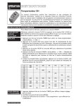
Figure'4:'Electronics'Subsystems'Flowchart
'
The' electronic' design' plays' a' key' role' due' to' the' large' number' of' peripherals' that' are' interfaced'
with,'as'well'as'having'both'analogue'and'digital'measurement'circuitry.'The'above'diagram'gives'an'
overview'of'the'electronic'interfacing'required.'The'schematics'(Appendix'4.3)'have'been'split'into'
three'key'sections'corresponding'to'the'three'individual'PCB’s'needed.'
'
The'front'of'the'board'consists'of'72'LEDs'for'time'display'with'an'additional'3'LEDs'for'weather,'1'
LED'for'AM/PM'display'and'1'system'LED.'Surface'mount,'0805'package,'red'LEDs'were'chosen'in'
order'to'meet'the'tight'board'dimensions,'whilst'still'being'moderately'easy'to'solder.'These'LEDs'
have' 180mcd' output' power' each' when' driven' at' full' current.' The' chosen' LEDs' have' reasonably'
bright'illumination,'with'the'colour'chosen'to'best'illuminate'through'the'given'red'acrylic.
'
The'large'number'of'LEDs'are'controlled'primarily'through'a'current'controlled'16'bit'shift'register;'
the' STP16CP05.' The' shift' register’s' current' controlling' ability' makes' it' very' suitable' for' this'
application'in'order'to'keep'brightness'levels'of'LEDs'relatively'the'same.'As'seen'in'the'schematic'
for'the'front'PCB,'it'is'seen'that'the'LEDs'are'arranged'in'5'distinct'layers'of'15'LEDs.''This'results'in'
only'1'of'5'layers'being'turned'on'at'a'time,'relying'on'the'inertia'of'vision'and'fast'multiplexing'to'
allow'for'the'addressing'of'LEDs'simultaneously'on'varying'layers.'The'current'controller'has'been'
set'to'around'20mA'per'output'line'(keeping'in'mind'a'20%'duty'cycle),'which'is'set'using'a'resistor'
(Rdext.)'of'1KΩ,'as'per'the'datasheet.
'
The'STP16CP05'has'an'enable'line'that'is'sent'PWM'signals'to'adjust'the'brightness'level'of'the'LEDs,'
a' key' feature' of' the' product' specification.' This' eases' the' MCU' load' from' adjusting' duty' cycles'
through'firmware.'The'layers'are'switched'using'BC337'NPN'transistors,'chosen'for'their'low'cost,'
high' collector' current' (0.8A)' capability,' and' fast' switching' functionality.' As' seen' in' the' schematic'
(Appendix'4.3.2)'the'transistor'emitter'is'current'controlled'by'the'driver,'doing'away'with'the'need'
of'a'current'limiting'resistor'on'the'MCU'output'pins.
'
The'microcontroller'selected'is'the'ATmega168,'which'was'based'on'a'number'of'factors,'including'
low' price,' large' level' of' input/output' pins,' and' specification' adherence.' This' microcontroller' gives'
8'
'
'