1
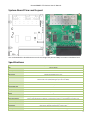
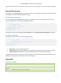
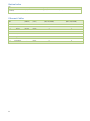
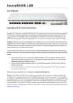
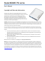
RouterBOARD 751 series User's Manual Copyright and Warranty Information Copyright and Trademarks. Copyright MikroTikls SIA. This manual contains information protected by copyright law. No part of it may be reproduced or transmitted in any form without prior written permission from the copyright holder. RouterBOARD, RouterOS, RouterBOOT and MikroTik are trademarks of MikroTikls SIA. All trademarks and registered trademarks appearing in this manual are the property of their respective holders. Hardware. MikroTik warrants all RouterBOARD series equipment for the term of fifteen (15) months from the shipping date to be free of defects in materials and workmanship under normal use and service, except in case of damage caused by mechanical, electrical or other accidental or intended damages caused by improper use or due to wind, rain, fire or other acts of nature. To return failed units to MikroTik, you must perform the following RMA (Return Merchandise Authorization) procedure. Follow the instructions below to save time, efforts, avoid costs, and improve the speed of the RMA process. 1. If you have purchased your product from a MikroTik Reseller, please contact the Reseller company regarding all warranty and repair issues, the following instructions apply ONLY if you purchased your equipment directly from MikroTik in Latvia. 2. We do not offer repairs for products that are not covered by warranty. Exceptions can be made for RB1000, RB1100, RB1200. 3. Out-of-warranty devices and devices not covered by warranty sent to Mikrotikls will be returned to the sender at sender's cost. RMA Instructions are located on our webpage here: http://rma.mikrotik.com Manual. This manual is provided “as is” without a warranty of any kind, expressed or implied, including, but not limited to, the implied warranty of merchantability and fitness for a particular purpose. The manufacturer has made every effort to ensure the accuracy of the contents of this manual; however, it is possible that it may contain technical inaccuracies, typographical or other errors. No liability is assumed for any inaccuracy found in this publication, nor for direct or indirect, incidental, consequential or other damages that may result from such an inaccuracy, including, but not limited to, loss of data or profits. Please report any inaccuracies found to [email protected] USER'S MANUAL ............................................................................................................................................................... 1 COPYRIGHT AND WARRANTY INFORMATION ................................................................................................................... 1 SYSTEM BOARD VIEW AND LAYOUT ................................................................................................................................. 3 SPECIFICATIONS ................................................................................................................................................................ 3 HARDWARE GUIDE ........................................................................................................................................................... 4 MEMORY AND STORAGE DEVICES ................................................................................................................................................. 4 Memory ............................................................................................................................................................................ 4 Storage Device ................................................................................................................................................................. 4 INPUT/OUTPUT PORTS ............................................................................................................................................................... 4 Ethernet ports .................................................................................................................................................................. 4 LEDS ...................................................................................................................................................................................... 4 USER'S GUIDE ................................................................................................................................................................... 4 POWERING............................................................................................................................................................................... 4 BOOTING OPTIONS .................................................................................................................................................................... 5 Onboard NAND Storage Device ........................................................................................................................................ 5 Booting from network ...................................................................................................................................................... 5 Operating System Support ............................................................................................................................................... 5 BUTTONS AND JUMPERS ............................................................................................................................................................. 6 WIRELESS DEVICE ...................................................................................................................................................................... 6 ROUTERBOOT ................................................................................................................................................................... 6 BOOT LOADER CONFIGURATION ................................................................................................................................................... 6 BOOT LOADER UPGRADING ......................................................................................................................................................... 6 PRIMARY BOOT LOADER ............................................................................................................................................................. 6 ROUTEROS FUNCTIONS .................................................................................................................................................... 7 FIRMWARE INFORMATION ........................................................................................................................................................... 7 FIRMWARE SETTINGS ................................................................................................................................................................. 7 APPENDIX ......................................................................................................................................................................... 7 CONNECTOR INDEX .................................................................................................................................................................... 7 BUTTON INDEX ......................................................................................................................................................................... 8 ETHERNET CABLES ..................................................................................................................................................................... 8 2 RouterBOARD 751 Series User's Manual System Board View and Layout You can download the board dimensions and case design files (PDF and DXF) from www.routerboard.com Specifications RouterBOARD 751U-2HnD / RouterBOARD 751G-2HnD CPU Memory AR7241 400MHz 32MB DDR SDRAM onboard Boot loader RouterBOOT Data storage 64MB onboard NAND memory chip Ethernet RB751U-2HnD: Five 10/100 Mbit/s Ethernet ports supporting Auto-MDI/X RB751G-2HnD: Five 10/100/1000 Gigabit ports with Auto-MDI/X MiniPCI slot Expansion USB 2.0 port CompactFlash slots - Serial port - LEDs Beeper Power, NAND activity, 5 Ethernet and 1 wireless LEDs + Power at the device DC power jack (5.5mm outside and 2mm inside diameter, female, pin positive plug) accepts 8-30V DC Power over Ethernet Ether 1 requires 8-30V DC (non 802.3af), to compensate for losses, it’s recommended to use 12V or more Power consumption Up to 7W Dimensions 113x138x29mm. Weight without packaging and cables: 230g Temperature Indoor device. Operational temperature: -20°C to +50°C Humidity Operational: up to 70% relative humidity (non-condensing) 3 RouterOS RouterOS v5, Level4 license Wireless specifications Wireless Integrated Wireless 2.4GHz 802.11b/g/n 2x2 MIMO Antenna 2x2 MIMO PIF antennas, max gain 2.5dBi, external MMCX option RX Sensitivity 802.11g: -96dBm (6Mbit/s) to -81dBm (54Mbit/s) 802.11n: –96 dBm (MCS0) to –78 dBm (MCS7) TX Power 802.11g: 30dBm (6Mbps) to 27dBm (54Mbps) 802.11n: 30dBm (MCS0) to 26dBm (MCS7) Modulations OFDM: BPSK, QPSK, 16 QAM, 64QAM; DSSS: DBPSK, DQPSK, CCK Hardware Guide Memory and Storage Devices Memory The RB751 has 32MB of built-in memory. There are no memory upgrade options. Storage Device The device is equipped with one built in NAND nonvolatile memory chip. Input/Output Ports Ethernet ports There are five individual Ethernet ports. Ports 2-5 are connected to a switch and can be switched together by an option in the RouterOS software. All cables made to EIA/TIA 568A/B cable specifications will work correctly (see Connector Index for pinout). Note that this port supports automatic cross/straight cable correction (Auto MDI/X), so you can use either straight or cross-over cable for connecting to other network devices. LEDs Ethernet LED lights up when a cable is connected, these LEDs don’t show ethernet activity, just connectivity. Wireless LED flashes on activity. Power LED indicates that the device receives power. ACT LED shows NAND activity and can be programmed to show other things via RouterOS LED menu. User's Guide Powering The device accepts powering from the power jack or from the first Ethernet port (Passive PoE): DC power jack (5.5mm outside and 2mm inside diameter, female, pin positive plug) accepts 8-30V DC The first Ethernet port accepts passive Power over Ethernet accepts 8-30V DC Under maximum load, the power consumption of this device is 7W 4 RouterBOARD 751 Series User's Manual Booting options RouterOS is the operating system of all RouterBOARD routers. Please see detailed configuration guide here http://wiki.mikrotik.com/wiki/Category:Manual Initial configuration includes the following: wirelesss AP with SSID „MikroTik” has been enabled, and bridged to ports Ether2-Ether5. This bridge has a DHCP server runni ng, so you can connect to the devide using the Web based „Webfig” interface from Ether2-Ether5 or from the wireless interface. Open http://192.168.88.1 in your browser, in the page that opens, select „Webfig” and log in with username „admin” and no password. The Ether1 port has a firewall on it, and a DHCP client, so it’s configured to be connected to your ISP. An alternative configuration option is the MikroTik Winbox utility (Windows only). Winbox can be used to connect to the default IP address of 192.168.88.1 with the username admin and no password. In case you wish to boot the device from network, for example to use MikroTik Netinstall, hold the RESET button of the device when starting it until the LED light turns off, and the device will start to look for Netinstall servers. In case IP connection is not available, Winbox can also be used to connect to the MAC address of the device. More information here: http://wiki.mikrotik.com/wiki/First_time_startup Onboard NAND Storage Device The RouterBOARD may be started from the onboard NAND storage chip. As there is no partition table on the device, the boot loader assumes the first 4MiB form a YAFFS filesystem, and executes the file called “kernel” stored in the root directory on that partition. It is possible to partition the rest of the medium by patching the kernel source. Booting from network Network boot works similarly to PXE or EtherBoot protocol, and allows you to the device from an executable image stored on a TFTP server. It uses BOOTP or DHCP (configurable in boot loader) protocol to get a valid IP address, and TFTP protocol to download an executable (ELF) kernel image combined with the initial RAM disk (inserted as an ELF section) to boot from (the TFTP server's IP address and the image name must be sent by the BOOTP/DHCP server). To boot the RouterBOARD computer from Ethernet network you need the following: An ELF kernel image for the loader to boot from (you can embed the kernel parameters and initrd image as ELF sections called kernparm and initrd respectively) A TFTP server which to download the image from A BOOTP/DHCP server (may be installed on the same machine as the TFTP server) to give an IP address, TFTP server address and boot image name Operating System Support MikroTik RouterOS starting from version v5 is fully compatible with RouterBOARD 751 series devices. If your device is preinstalled with an earlier RouterOS release, please upgrade RouterOS to v5.8 or newer. 5 Buttons and Jumpers RouterOS reset jumper hole (on the bottom of case) – resets RouterOS software to defaults. Must short circuit the metallic sides of the hole with a screwdriver and boot the device. Hold screwdriver in place until RouterOS configuration is cleared. RouterBOOT reset button (RES, front panel) has two functions: o Hold this button during boot time until LED light starts flashing, release the button to reset RouterOS configuration (same result as with RouterOS reset hole) o Hold this button during boot time longer, until LED turns off, then release it to make the RouterBOARD look for Netinstall servers. Wireless device RB751U includes a 2GHz 802.11b/g/n wireless device built in. It has PIF type antennas (2.5dBi) built into the case, and one MMCX connector for an optional external antenna. RB 751U has 3 built-in wireless antennas Chain0 o o Chain1 o o one antenna for TX one antenna for RX one antenna for TX/RX MMCX connector for external antenna To enable the external MMCX connector, set „antenna mode: antenna-b” in RouterOS wireless settings, in the HT tab of Winbox. Note: enabling the external antenna disables the built-in Chain1 antenna. RouterBOOT The RouterBOOT firmware (also referred as Bootloader here) provides the basic functionality to boot an Operating System. It supports serial console via the onboard serial port at the boot time. The loader supports booting from the onboard NAND device and from a network server (see the respective section for details on this protocol). Boot Loader Configuration This device doesn’t come fitted with a serial port connector, so all Bootloader specific settings must be done in RouterOS. See „RouterOS functions” Boot Loader Upgrading The boot loader is needed to initialize all the hardware and boot the system up. The boot loader upgrading is possible from MikroTik RouterOS, from within the “/system routerboard” menu. Updates are included with each RouterOS update. The procedure is described in the MikroTik RouterOS manual: http://wiki.mikrotik.com/wiki/Manual:Bootloader_upgrade Primary Boot Loader There are two boot loaders present on the NOR flash memory chip. Secondary is the main one, that is executed by default. This is the one that can be upgraded. In case something goes wrong in the upgrade process, or you have set some incorrect settings that render it unusable, you can load the Primary boot loader by holding the Software Reset 1 button (S401), connecting the power, and then releasing the button/jumper. 6 RouterBOARD 751 Series User's Manual The Primary boot loader has the default settings, which can not be changed. It is also not possible to upgrade it. RouterOS functions The default OS of RouterBOARD devices is RouterOS, when the routerboard.npk package is installed, RouterOS can configure some RouterBOARD hardware settings Firmware information This menu displays RouterBOARD model number, serial number, the current boot loader version and the version available in the current software packages installed. [admin@MikroTik] > system routerboard print routerboard: yes model: "rb751u" serial-number: "154201C1DD3C" current-firmware: "2.26" upgrade-firmware: "2.27" [admin@MikroTik] > The firmware version can be upgraded from RouterOS by using “/system routerboard upgrade” command. Firmware Settings Boot loader settings are also accessible through this menu. [admin@MikroTik] > system routerboard settings print boot-delay: 2s boot-device: nand-if-fail-then-ethernet boot-protocol: bootp enable-jumper-reset: yes [admin@MikroTik] > Boot-device: use this to enable Netinstall Boot protocol: for Netinstall use Bootp, for installing other operating systems, you need to use DHCP Enable-jumper-reset: Disable this to avoid accidental setting reset via the onboard jumper The Software Reset jumper , which resets both boot loader settings and RouterOS settings by default, can be disabled in this menu (it will still reset the boot loader settings). Appendix Connector Index Ether1-5 RJ45 Ethernet 100Base-T ports, Ether1 accepts passive PoE power Power Power Jack (8-30V DC) USB USB 2.0 port for connecting 3G modem, storage device or GPS module (unlabeled) ANT MMCX connector for connecting an external antenna 7 Button Index RES Software Reset 1 button. (see ”Buttons and Jumpers”) RESET (unlabeled) Software Reset 2 jumper hole. Resets RouterOS settings (see „Buttons and Jumpers”) Ethernet Cables RJ45 Pin Color Function (100Mbit) Function (1Gbit) RJ45 pin for Straight cable (MDI, EIA/TIA568A) RJ45 pin for Crossover cable (MDI-X, EIA/TIA568B) 1 Green TX+ Data Data A+ 1 3 2 Green/White TX- Data Data A- 2 6 3 Orange RX+ Data Data B+ 3 1 4 Blue - Data C+ 4 4 5 Blue/White - Data C- 5 5 6 Orange/White RX- Data Data B- 6 2 7 Brown - Data D+ 7 7 8 Brown/White - Data D- 8 8 8