1
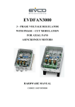
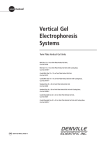
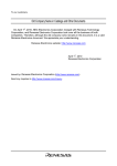
SERVICE MANUAL
SPIROBANK & SPIROBANK G
Pag. 1 / 15
SPIROBANK HARDWARE DESCRIPTION
Fig.1
SYSTEM BLOCK DIAGRAM
The hardware system is made up of 6 main blocks:
1.
2.
3.
4.
5.
6.
Microprocessor
I/O periferals
RAM
RTC
Power supplì
Reset circuit
These main blocks are illustrated in fig.1.
The narrow lines serve to show the distinction between the power up (ON) , power down (OFF) and
reset circuits.
Now we can look at the main characteristics within each block.
Microprocessor
Motorola 68HC11F1FN, at the “heart” of the system (IC3), and all of the other system components
are controlled from this uP.From within the microprocessor:
a) the 8 –bit DATA BUS controls the LCD and also controls data exchange to and from the
external static RAM (IC9).
Pag. 2 / 15
b) allocates a 16 bit ADDRESS BUS to the 128kb *8bit RAM
c) the I/O address space is automatically controlled by means of 2 of the four built-in CHIPSELECT outputs (CSIO1 for the LCD, CSPROG for the external RAM)
d) another CHIP-SELECT line (CSGEN) controls the access to the two –page RAM,64kb each
page.
e) Has 8 A/D inputs, two of which (TEMP and HVZB) are used for reading the temperature
sensor and the measurement of the battery level of the 9V main battery.
I/O Periferals
a) Keyboard with 5 keys :
Desription of the 7 pins of the keyboard connector (CON2):
1)
2)
3)
4)
5)
6)
7)
direct power supply ( circa 6V,VZB) unregulated
manual power –down key (OFF)
regulated power supply 5V (VCC)
key 1
key 2
key 3
key CR /Return/Enter) and manual power on (ON)
The 1,2,3 and CR keys are connected to the 4 input ports of the uP for reading the pressed key when
the system is switched on.
When instead the machine is switched off the only active key is the CR which allows the unit to be
switched on.
The manual power off is activated by the OFF key.
b)
LCD
2) Line /16 character per line display.
The LCD is connected to the uP via the 8 bit DATA BUS and 4 lines of control.
c)
RS232
Bidirectional serial port asincronous controlled by the uP via its serial port.
Towards the PC the port has 5 lines (CON3) configured as follows:
1
2
3
4
5
VB (9V circa)-direct power on unregulated
RX
TX inverted
TX
RTS
Pag. 3 / 15
d) Temperature sensor
Transducer of temperature/voltage (IC7) NATIONAL LM 35. The output signal, amplified by way
of an operatinal amplifier (IC6) is connected to one of the A/D channels of the uP ( line TEMP ,
100mV=1 degree Centigrade).
e) Flow meter
Sensor for the measurement of the flow and volume air.
The sensor is comprised of:
Mechanical parts
(a)
(b)
(c)
A tube in policarbonate –IR (transparent to infrared light)
A pair of swirl ( deflectors) positioned at the exit of the tube , in order to create a vortice of
the moving air within the axis of the senmsors.
A moving part ( rotor), the velocity of rotation of which is proportional to the flow of air
passing through the tube .
Electrical parts
(a) Two pairs of infrared transmitters/receivers positioned as shown infig.2.
(b) A signal conditioning circuit (C%,C6,R12,D5,D6,IC8) to rectify the output signal from the
two infrared light receivers.
The rotation of the rotor causes the interruption of the infrared rays, thus creating a signal which has
a frequency directly proportional to the flow.
The measurement of the flow of air which passes through the tube is therefore proportional to the
number of interruptions of the infrared rays.
The phase difference ∆ϕ ( positive or negative) between the signals from each of the two infrared
receivers (IR1 and IR2) depends upon the direction of rotation of the moving rotor and therefore
supply the information on the direction (expiration or inspiration) of the air flow.
In detail, ∆ϕ >0 for expiratory flow, ∆ϕ < 0 for inspiratory flow.
Pag. 4 / 15
Fig.2
Diagram of the turbine operation
Pag. 5 / 15
Fig.3
Output of the two infrared receivers IR1, IR2 for inspired and expired air flows.
The two wave trains are squared by a Schmitt trigger (IC8) and then sent to two input ports of the
uP. The uP has the possibility to switch the turbine on or off ( by switching on or off the infrared
transmitters) by way of a second output port.
f) buzzer
Piezoelectric buzzer with internal oscillator, with resonance frequency of 4KHz.
The activation of the buzzer is controlled directly via two output ports of the uP.
RAM
Static RAM 128k* 8 bit (IC9). The power down phase is controlled by the RESET signal and
data retention (backup) is powered by the 3.6V lithium battery (IT1).
Pag. 6 / 15
The RAM is configured in two pages each of 64 Kbyte.The access to the pages is controlled directly
from an output port of the uP ( line CSGEN).
Page 1 contains the measured spirometric data ( database) and the application software.
Page 2 contains a reserve copy of the software which is utilised only in the case of a checksum error
in page 1. The checksum is controlled every time that the system is switched on.
In the case of a malfunction a message on the display informs the user that the data contained in the
RAM memory have been cancelled.
Timer
Real Time Clock connected to the uP via an I/O line, and via which bidirectional serial
communication is also managed. Contains the current date and time.
Access to the timer is regulated by a security code of 64 bit which therefore avoids unauthorised
changes to the contents of the timer and of its internal memory, which also contains all of the
configuration data of the system software.
In case of a malfunction the default configuration is reinstalled and a message informs the user that
the data in the timer have been cancelled.
By use of an output signal(IRQ), the machine can be switched on at a preset time. The data
retention (backup) is assured by the 3.6V lithium battery (IT1).
Power supply
The main power for the system is supplied by a 9V battery (alcaline or similar). The back up power
is supplied by an internal lithium battery of 3.6V, attached directly to the PCB.
The maximum power consumption of the machine (when the flow meter is also in operation) is
25mA. The consumption when the machine is in operation but without the flow meter switched on
is 12mA.Each time that the machine is in input phase the machine is put into a wait state and the
consumption is then 3mA.
The consumption of the lithium battery active when the system is switched off (data retention
mode), at an ambient temperature of 25 degrees is approximately 1uA.
The power supply is made of two integrated circuits:
(a) A JK flip-flop (IC2), to carry out the function of power supply control.
(b) Three functional blocks are connected to this circuit, which are able to power up and/or
power down the system.
1) Manual power on and power off:by keyboard
2) Automatic power on: by RS232 or by RTC timer
3) Automatic power off:by uP
Pag. 7 / 15
(c) A linear 5V regulator (IC5),with control input for:
1) shutdown to manage the ON/OFF of the Vcc voltage
2) Low battery to compare the voltage of the backup battery (lithium) with the voltage
value preset for low battery (set at 2,8V).
When the system is switched off (OFF) the regulator is put into shutdown mode,and
the total power consumption from the 9V battery is reduced to 1 uA.
Reset
The reset signal is generated by a voltage sensing circuit (IC4).
The reset signal is activated when the voltage at the input is < 4.7V.
The rest is applied to the uP and to the RAM where it takes the role of POWER DOWN, for data retention
(BACKUP).
Pag. 8 / 15
Pag. 9 / 15
Pag. 10 / 15
Pag. 11 / 15
SE.0001.001
Bill Of Materials
May
Revised:
May 27, 2001
Revision: 1
27, 2001
12:17:35
Page
Item Quantity Reference
Part
Cod. Art.
_____________________________________________________________________
1
1
BZ1
BUZZER
560020
2
1
CON1
CON16
130004
3
2
CON3,CON2
CON7
113352-123700
4
1
CON4
CON2
960038
5
1
CON5
CON14
120324
6
2
C1,C2
22p
831708
7
5
C3,C7,C9,C10,C11
100n
831746
8
3
C4,C5,C6
1u
810068
9
1
C8
47u
810036
10
1
D1
RB731U
600050
11
3
D2,D5,D6
RB751
602635
12
1
D3
CR10R
253104
13
1
D4
RB715F
600060
14
1
IC1
DS2404S
644693
15
1
IC2
GD4027BD
640313
16
1
IC3
MC68HC11F1
648171_PU
17
1
IC4
TC54VC
640290
18
1
IC5
MAX667
644930
19
1
IC6
LMC7101
649331
20
1
IC7
LM35
641527
21
1
IC8
74HCT14
648018
22
1
IC9
GM76C8128LL
646452
23
4
IR1,IE1,IR2,IE2
LED_1
631314-630430
24
1
IT1
VL 3.6V
970232
25
1
JP1
JUMPER
26
17
RR1,R1,R2,R5,R6,R7,R10,
R11,R14,R17,R19,R20,R21,
R22,R23,R28,R29
4K7
Pag. 12 / 15
712676
1
SE.0001.001
Bill Of Materials
May
Revised:
May 27, 2001
Revision: 1
27, 2001
12:17:35
Page
Item Quantity Reference
Part
Cod. Art.
_________________________________________________________
27
6
R3,R4,R8,R12,R13,R25
100K
712708
28
1
R9
150
712638
29
1
R15
8M2
712782
30
2
R16,R18
10M
712784
31
1
R24
10K
712684
32
2
R27,R26
510K
712725
33
1
TP1
TP
34
1
X1
32768Hz
680500
35
1
X2
4.9152MHz
680510
36
1
tab1
TABELLA
37
1
tab2
MIR
Pag. 13 / 15
2
Pag. 14 / 15
Pag. 15 / 15