1
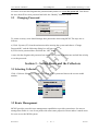
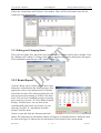
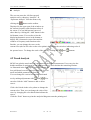
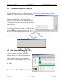
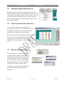
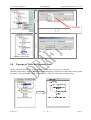
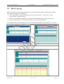
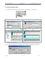
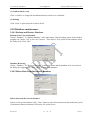
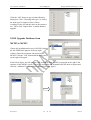
User’s manual of MCMe3.0
www. sendig.com
Beijing SENDIG Technology Co. LTD
BEIJING SENDIG TECHNOLOGY, LTD.
USER’S MANUAL
For the
MCMe3.0
Machinery Condition Monitoring And
Diagnosis Software System
The information that provided in this Manual is believed to be reliable. However, Sendig
Technology assumes no responsibility for inaccuracies or omissions. Sendig Technology
assumes no responsibility for the use of this information, and all use of such information
shall be entirely at the user's own risk. Specifications are subject to change without notice.
No patent rights or licences to any of the functions described are implied or granted to any
third party. Sendig Technology does not authorise or warrant any Sendig Technology
product for use in life support devices or systems.
E-mail: [email protected], [email protected]
Fax: +86 10 82895320
Telephone: +86 10 82895321
Address: International Science and Technology ChuangYe Garden, ShangDi
Beijing, P. R. China, Post code: 100085
http://www.sendig.com
Revision B
1
of
1
06-4-10
User’s manual of MCMe3.0
www. sendig.com
Beijing SENDIG Technology Co. LTD
General
MCM3 is a Windows-based application software released by Beijing Sendig Technology
Co., for Sendig-900 series portable data collectors and online machinery condition
monitoring systems.
Features:
Integrated software for portable data collector and online monitoring system
Integrated most current technology for machinery condition monitoring and
diagnosis
Single user to networking configuration (both C/S and B/S mode)
Clear view of the machinery alarm / health condition in form of alarm tree
Full functionality route management
Rich vibration analysis capabilities for time-domain and frequency-domain
diagnosis
Machinery picture management capability enables user to define and see more
clearly the measurement location in workshop and equipment
All statistical data can be output in the form of MS Office documents for report
generation, modify and save. Statistical data are classified into the following:
• Status reports of all equipment
• Latest measurement reports
• Most recent measurement reports
• Route status and schedule report
• Current condition report
Windows 98/ME/2000 compatible
3 levels threshold setting
Automatic fault detection by overall and hundred band spectrum
Trending of overall and spectrum with selectable start & end date
Multi-level user authorization
Easily communicate with other department through ERP or asset management
systems
●
Section 1 – System Installation
1. System Requirements
CPU: Pentium MMX200 or higher;
RAM: no small than 32MB;
Operating System: Windows 98/ME/2000/XP
Revision B
2
of
2
06-4-10
User’s manual of MCMe3.0
www. sendig.com
Beijing SENDIG Technology Co. LTD
2 Installation
1) Double click the file “setup.exe”;
2) Follow the following steps until completion of installation.
Read the agreement carefully. Choose Yes
to accept the agreement. Go to the next step
and select your installation directory.
Revision B
3
of
3
06-4-10
User’s manual of MCMe3.0
www. sendig.com
Beijing SENDIG Technology Co. LTD
3) Restart the computer if required and re-run the installation program if an error occurs during
installation. If the installation is still unsuccessful, please contact us.
4) A shortcut will be shown for MCM3 on both the Windows desktop and in the Start Menu
following successful installation. Double-click the MCM icon on the desktop to enter the system.
Section 2 – User Management
2.1 System Administrator
There will be a highest priority user named System Administrator for maintaining of the system
after successful installation. The password is blank. Please remember to change the password the
first time you use the system.
2.2 Add/Delete a User
Click “System (S)” from the main menu and choose “User Administration”. A user administration
sub-window illustrated in the following figure will pop out. You can add lower level users, change
the passwords of lower level users or delete lower level users here.
To add a new user, enter an account for the new user in the pull-down box of “Username”, choose
a lower level entity in the pull-down box of “Level of Authority” and click the “Add” button after
entering a password.
To delete a user, choose a lower level user in the pull-down box of “Username” and click the
“Delete” button.
Revision B
4
of
4
06-4-10
User’s manual of MCMe3.0
www. sendig.com
Beijing SENDIG Technology Co. LTD
If a lower level user has forgotten his password and you have to re-set the password, first choose
the user, then fill in a new password and click the “Modify” button to finish.
2.3
Changing Password
To ensure security, users should change their passwords when using MCM. The steps are as
follows:
a) Click “System (S)” from the main menu after entering the system and choose “Change
Password(R)”, and the following dialog box will pop out:
b) Fill in a new password here and click the “OK” button.
A user who has forgotten his password can contact the System Administrator and ask him to help
re-set the password.
Section 3 – Setting Route and the Collectors
3.1 Selecting Collector
Click “Collector Selection(s)” in the main menu of the system and choose the correct model
number.
3.2 Route Management
MCM3 provides powerful route management capabilities to provide convenience for users to
manage data. Route is a set of test points with some same properties. Route makes it much easier
for users to use the MCM system.
Revision B
5
of
5
06-4-10
User’s manual of MCMe3.0
www. sendig.com
Beijing SENDIG Technology Co. LTD
Choose the “Setup Route and Collector” sub-window. There will be four buttons in the far left
column for route management.
3.2.1 Editing and Changing Route
First, select test points to be put in the route into the “select” column with the above method. Click
the “Editing route” button or “Change route” button and the route property dialog box will appear.
Fill in information and click the “OK” button to finish.
3.2.2 Route Report
Click the “Route report” button and the route report
dialog box as illustrated in the following figure will
appear (the yellow color indicates that it is already
beyond the test date). The following dialog box will
pop out upon system starting up if there is an alarm
route. You can close reminding messages at starting
up by choosing “System” “Close Route Schedule
Prompt” from the menu. You can activate the
reminding dialog box when you want to see it by
choosing “System” “Open Route Schedule
Prompt” from the menu.
Choose a route and click the “Measurement Info”
button. The following test information window will appear (as illustrated below). Different colors
are used in the figure to indicate the test information of test points for the current month.
Revision B
6
of
6
06-4-10
User’s manual of MCMe3.0
www. sendig.com
Beijing SENDIG Technology Co. LTD
3.3 Point Status in the Route
There might be some points in the route that will not be used for a period of time. In this case, set
such points to “Suspended”. The steps are as follows: Choose a route from the items in the left part
of the main window. Then select the route you want to change. Choose the points you want to
change in the point’s column on the right and change their status to “Suspended” (see the
following figure). If you want to use the points again, change their status to “In use”.
3.4 Data Upload
Measured data can be uploaded from collector to computer.
Upload of Overall value
Power on data collector and
connect it with the serial port of
the computer. After the display
of the data collector is in stable
condition, choose from the
main menu “Collection”, then
“Overall value from collector”.
The system will upload the
overall data (see figure right).
The upper part of the dialog
box displays the data to be
uploaded and in the large list
box is the point icon under
upload. You can see its color
meaning by clicking the “Help”
button in the top right corner.
The following dialog box is a report for data upload. Data should be stored into the database
after upload. Otherwise, the data will be lost.
Revision B
7
of
7
06-4-10
User’s manual of MCMe3.0
www. sendig.com
Beijing SENDIG Technology Co. LTD
The following is a dialog box with four extra measurement points (also called unscheduled points).
Upload of waveform data
Choose from the main menu “Collection”, then “Waveform from collector”, you can see the
following figure. Select a saved waveform from the left list, hold the left key of the mouse and pull
to the waveform display window on the right. Waveform files are stored in the “Wave File”
sub-directory under the installation directory of MCM3.
Revision B
8
of
8
06-4-10
User’s manual of MCMe3.0
www. sendig.com
Beijing SENDIG Technology Co. LTD
Section 4 – Data Analysis
4.1 Spectrum Analysis
Plotting of the Alarm Spectrum
For each point, there are three basic spectral
curves, the reference curve, the alarm
threshold curve and the dangerous threshold
curve that have to be plotted prior to the
spectral analysis. The steps are: choose
“Analysis”, and “Draw alarm spectrum”,
then the spectrum plotting window as
illustrated below will pop out.
First, choose a point in the pull-down box at
the top left corner. Then, select a measured
spectrum (reference spectrum) in the
pull-down box at the bottom left corner. Fill
in relevant values in the “Auto-spectrum” column. Click the “Create spectrum” button to
automatically generate the dangerous and the alarm spectrum. If you are not satisfied with the
spectral curves automatically generated, you can click the “Draw alarm spec” or the “Draw
dangerous spec” button in the “Manual Spectrum” column, and plot your desired alarm curve or
dangerous curve in the plotting region in the window by moving the left key of the mouse. Save
your plotting results after you finish. And you will be able to perform the spectral analysis.
Revision B
9
of
9
06-4-10
User’s manual of MCMe3.0
www. sendig.com
Beijing SENDIG Technology Co. LTD
Analysis
The user can enter the 100-line spectral
analysis tool by choosing “Analysis”
“Spectrum Analysis” from the menu or by
clicking the
button on the toolbar.
Displayed in the upper part of the window are
the current frequency and vibration values of
the cursor. You can add spectral curves of
other dates by clicking the “Add” button in the
left bottom corner. You can also select the
displaying harmonic cursor in the bottom to
display the 10 harmonic cursor lines and the
window of frequency and vibration value.
Besides, you can change the curve to the
current color (the far left color on the color palette) by clicking the color box indicating color of
the spectral curve. To change the scale of the axes by clicking the
and
buttons.
4.2 Trend Analysis
MCM3 can plot the trend curve of equipment based on the measurements. Users can view the
health condition of equipment in a straightforward way and calculate the remaining lifetime.
As illustrated in the right figure, you can select in the
four pull-down boxes the period of analysis, forecast
mode and which parameter for forecast.
You can change the vertical axe and the horizontal
axe by making adjustments with
and
. You
can also click the “Add” button to add or delete
curves.
Click color blocks in the color palette to change the
current color. Then you can change the color of the
curve by changing the color blocks that indicate the
curves.
Click the “Print” button to print the analytical diagrams onto the painting tool.
Revision B
10
of
10
06-4-10
User’s manual of MCMe3.0
4.3
www. sendig.com
Beijing SENDIG Technology Co. LTD
3 Dimension Spectral Analysis
MCM3 provides three-dimensional spectral waterfall curves arranged according to dates for the
same measurement point (see the following figure). Displayed in the middle of the curve in the
window is a 3D spectral waterfall figure. On the right
is the vibration value and corresponding date to the
spectral curve. Displayed in the upper part is the
frequency and amplitude of the cursor position.
Besides, the system also provides blanking capability
to provide users with more convenience for viewing of
waterfall curves.
Users can change the slope, vertical spacing, spectral
curve height, spectral curve width, etc. of the waterfall
at the lower line of the window. They
curve via
can also select measurement point names and date
ranges, etc. through the pull-down box.
Click “Date Vibration curve” at the upper of the window to pop out the date and amplitude
window (see the following figure).
4.3 Point Status Indicated by Color
In the point window at up right, the color red
indicates that the recent measurement data has
exceeded the dangerous threshold. The color
yellow indicates that the recent measurement
data exceeds the alarm threshold. And the color
white indicates that it is normal (see figure on
the right).
Section 5 –Data Management
Revision B
11
of
11
06-4-10
User’s manual of MCMe3.0
www. sendig.com
Beijing SENDIG Technology Co. LTD
5.1 Manually Input Measurement
MCM3 supports manual input of measurements. Choose
equipment on the structure tree and click “Add point” to add
a new point in the points column. In the same way, choose a
point and click the “Add measurement” shortcut button to
add a measurement data. You may manually input its value
after finishing adding.
5.2
Node Icon in the Structure Tree
Icons on the tree structure in the main screen
represent units of all levels. If an alarm tree is used
for display, there may be other icons to show the
condition of all machinery under each unit.
The icons shown in the right figure are defaults of
the system. You can change them by choosing
“System” “Set Node Icon” from the menu. Then
in the dialog box popping out you may edit the node
icons.
5.3
Edit the Structure Tree
To add and delete of a node, the first step is
to choose the node in the tree structure tree.
Then, right-click the mouse and choose the
desired operation from the menu popping
out. You can also execute corresponding
operation from the sub-menu of “Editing”
from the main menu (see figure right).
The figure below shows the adding process
of a boiler workshop in the first steel
workshop.
Revision B
12
of
12
06-4-10
User’s manual of MCMe3.0
www. sendig.com
Beijing SENDIG Technology Co. LTD
Choose node type.
Product line
Click the “Yes” button after filling in the node
name.
Adding is successful.
5.4
Copying of Node in Structure Tree
Drag a unit node with mouse on the structure tree to copy or to move (see figure).
Example below shows how to MOVE the first workspace to under the second plant by drag it with
the mouse. You can COPY a node by holding the “Ctrl” key at the time of mouse drag.
Revision B
13
of
13
06-4-10
User’s manual of MCMe3.0
www. sendig.com
Beijing SENDIG Technology Co. LTD
5.5 Block Copying
MCM3 provides block-copying capability for points and measurements with identical contents.
The steps of operation are as follows:
Choose the point or measurement data to be copy and click the “Copy point” (“Copy
measurement”) shortcut button;
Choose the destination equipment (or choose the destination point) on the structure tree;
Choose “Insert point” or “Insert measurement” with the shortcut button;
For example, follow the following steps to add all measurement data of the point FJ2-1 to FJ2-4:
Choose source, then “copy measurement”
Revision B
Choose destination point, then insert
14
of
14
06-4-10
User’s manual of MCMe3.0
www. sendig.com
Beijing SENDIG Technology Co. LTD
5 .6 Search and Sort Data
As illustrated in the following figure, search can be “Search node” or “Search point”.
Search node
Search point
Supporting “F3” key
Sorting of measurement data
You can use data sorting to view measurement data within a period of time of all points in
the point column by clicking the shortcut button “Filter”. The following dialog box will pop out.
Revision B
15
of
15
06-4-10
User’s manual of MCMe3.0
www. sendig.com
Beijing SENDIG Technology Co. LTD
Click the “OK” button and all data in the period of time will be listed in the measurement column.
5.7 Management of Units and Equipment Pictures
Click a node in the structure diagram in the main window and you will see the picture of the node
below the structure tree.
Click “Picture” button and the “Image Management” dialog box will pop out.
If you want to add or modify a picture, they click the “Locate” button to find the picture to be
added and then save it into the database.
In “Config”, you may select a drawing tool, e.g. Paint, PhotoShop.
The new tool will also be used in printing of trend analysis and 3-D spectral analysis.
“Draw” to modify the current picture by the drawing tool.
Revision B
16
of
16
06-4-10
User’s manual of MCMe3.0
www. sendig.com
Beijing SENDIG Technology Co. LTD
5.8 Unscheduled Measurement
Points not set in the route but measured on
site are called unscheduled points. Their
measurements are put under the
“Unscheduled Measurement” of the
structure tree temporarily because they
have no corresponding points to put after
uploading from collector.
Data of unscheduled points should be stored under respective test points after uploading from
collector. The steps are as follows:
Need English
Choose a point.
Right-click on
an unscheduled
measurement to
pop out a menu.
Adding finish.
5.9
Alarm History
(1) View alarm event record
Choose alarm type and the time period.
Click the “Refresh” button to view
alarm records within the time period. If
the box on the left of the timeframe is
not chosen, all records within the time
period will be displayed.
(2) Delete history records
Choose alarm type and click the
“Delete” button to delete all records
selected (note: undelete is not possible
so be careful).
Revision B
17
of
17
06-4-10
User’s manual of MCMe3.0
www. sendig.com
Beijing SENDIG Technology Co. LTD
(3) Confirm alarm event
Click “Confirm” to change all unconfirmed alarm records to be confirmed.
(4) Printing
Click “Print” to print selected records to Excel.
5.10 Database maintenance
5.10.1 Backup and Restore Database
Backup of the Current Database
Choose “Database” “Backup database” in the main menu. Choose backup option in the window
popping out. Choose “All” to save all. Choose a “Time Period” for a period of time and then select
the time period. Click “OK”.
Database Restoring
Choose “Database” “Recover Database” in the main menu and the database to be recovered in
the dialog box popping out. Click “Open” to restore the database.
5.10.2 Delete Data from the current Database
Delete data from the current database
Choose a time period and then click “Clear” button to clear all measurement data within the period.
Cleared data cannot be undeleted. Therefore, be careful in use.
Revision B
18
of
18
06-4-10
User’s manual of MCMe3.0
www. sendig.com
Beijing SENDIG Technology Co. LTD
Append data.
Choose the database you want to append. Click “Append” to append all measurement data in the
selected database to the current system database.
5.10.3 View a saved database
a) Choose “Database”
“Browse Database” in the
main menu and then select the database you want to view
(note: for backup database and system database only. The
default database is system database).
(1) If you choose “new database”, click the file folder icon in
the new database column. After choosing the database, the
path for the database will appear in the path dialog box. Click “OK”.
(2) If you choose the default database, click the “OK” button to restore the original system
database.
Note: This function is only for the purpose of viewing. The next time you restart the MCMe3
program, the system database will be used but not the database you opened here.
5.10.4 Upgrade of Database from MCM1 to MCM3
Follow the following steps to upgrade database of MCM1 software previously used.
Choose “Database maintenance” “From MCM1 to MCM3” in the main men, and choose the
subdirectory “DBFS” under the MCM1 installation directory in the dialog box popping out (see the
following figure.
Revision B
19
of
19
06-4-10
User’s manual of MCMe3.0
www. sendig.com
Beijing SENDIG Technology Co. LTD
Click the “OK” button to pop out the following
dialog box. Click “Choosing node type” to choose
the node type for import of data. Choose
workshop on the left and the node on the structure
tree. Then, click “Import data” to finish database
upgrade.
5.10.5 Upgrade Database from
MCM2 to MCM3
Choose the installation directory of MCM2 (when
the file USER.PAS appears in the top right
column). Enter the username and password for
MCM2. Click the “OK” button and the dialog box
on the right will appear.
In the below figure, the left column is the workshop of the MCM2 system and on the right is the
structure of the MCM3 system. Choose the workshop and destination MCM3 node to import and
click the “Add data” button to finish (see the following figure).
Revision B
20
of
20
06-4-10