1
US008045982B2
(12) United States Patent
(10) Patent N0.:
(45) Date of Patent:
Khoo et a].
(54)
METHODS FOR SITE SELECTION IN A
MULTI-SITE COMMUNICATION SYSTEM
(56)
US 8,045,982 B2
Oct. 25, 2011
References Cited
U.S. PATENT DOCUMENTS
(75) Inventors: Hun Weng Khoo, Pul (MY); John P.
Belmonte, Schaumburg, IL (US);
Dipendra M. ChoWdhary, Hoffman
Estates, IL (US); Yueh Ching Chung,
Pul (MY); David G. Wiatrowski,
Woodstock, IL (US)
(73) Assignee: Motorola Solutions, Inc., Schaumburg,
IL (US)
Notice:
Subject to any disclaimer, the term of this
patent is extended or adjusted under 35
U.S.C. 154(b) by 573 days.
Filed:
2/2001
7,369,869 B2
5/2008 Wiatrowski
Brown et a1.
............... .. 455/434
2004/0033804 A1*
2/2004
2008/0014928 A1
2008/0014934 A1
1/2008 Chen
1/2008 Balasubramanian et a1.
Binzel ......................... .. 455/437
OTHER PUBLICATIONS
PCT International Search Report Dated Apr. 26, 2010.
* cited by examiner
Primary Examiner * Kamran Afshar
Assistant Examiner * Dung Lam
(74) Attorney, Agent, or Firm * Valerie M. Davis
(57)
(21) App1.No.: 12/253,478
(22)
6,185,423 B1 *
ABSTRACT
A device detects a ?rst signal on a channel that is one of a
plurality of channels arranged in a ?rst order on a list, With
each channel being associated With a different site in a multi
Oct. 17, 2008
site communication system. Upon detecting the ?rst signal,
(65)
Prior Publication Data
US 2010/0099404 A1
(51)
Apr. 22, 2010
site the site associated With the channel having the signal With
the highest recorded signal strength. The device rearranges
Int. Cl.
H04W4/00
(52)
the device attempts to measure and record signal strength of a
signal at each channel on the list based on the ?rst order
beginning With the detected ?rst signal, and selects as a home
(2009.01)
US. Cl. ................... .. 455/434; 455/433; 455/432.1;
455/67.11; 455/435.2; 370/332
(58)
Field of Classi?cation Search ................ .. 455/433,
455/434, 432.1, 67.11, 435.2; 370/331, 332,
370/328
the channels on the list into a second order based on the
recorded signal strengths With the home site channel at the
top. If necessary, the radio attempts to awaken its repeaters
one after another based on the second order until a repeater is
found to transmit a signal.
See application ?le for complete search history.
13 Claims, 4 Drawing Sheets
1—
220 “
CHANNEL SORT AND
SELECT HOME CHANNEL
204 1
START PAssIVE CHANNEL SCAN
WITH HOMESITE CHANNEL
216
W
SELECT NEXT CHANNEL
IN ORDER OF CHANNEL
LIST
206
SIGNAL DETEcTED?
224 1
RESTART
CHANNEL SCAN
ALL CHANNELs ON
LIST SCANNED?
210“
MEASURE AND RECORD
SIGNAL STRENGTH
218“
PROCESS CALL
US. Patent
0a. 25, 2011
Sheet 1 014
US 8,045,982 B2
1
FIG.
US. Patent
Oct. 25, 2011
US 8,045,982 B2
Sheet 2 0f4
220 i
zozw/
CHANNEL SORT AND
/
\ \
SELECT HOME CHANNEL
/S/|GNAL STRENGTH > TH 0N~ \ No
\
\
HOME SITE AND RADIO
/
/ ’
\ _NOT IN A CAL}. /
\ \
/
YES
204 ?
START PASSIVE CHANNEL SCAN
WITH HOMESITE CHANNEL
216
i
SELECT NEXT CHANNEL
IN ORDER OF CHANNEL
v
206
LIST
SIGNAL DETECTED?
224 i
222
RESTART
FIRST SIGNAL DETECTED?
CHANNEL SCAN
208
SYNC PRESENT AND
OLOR CODE MATCHES'P
ALL CHANNELS ON
LIST SCANNED?
2101
MEASURE AND RECORD
SIGNAL STRENGTH
218i
RELEVANT CALL?
FIG. 2
YES
200
PROCESS CALL
US. Patent
0a. 25, 2011
SIGNAL READY FOR
TRANSMISSION
{
402
SELECT FIRST CHANNEL TO (
START ACTIVE SCAN
404
Sheet 4 0f4
US 8,045,982 B2
V
406
SIGNAL DETECTED?
f,
410
TRANSMIT SIGNAL
AN REPEATER
ON CHANNEL
POLITENESS?
416
r— 420
‘ LL CHANNELS ON
NOTIFY THAT ACTIVE CHANNEL
LIST TRAVERSED?
SCAN UNSUCCESSFUL
SELECT NEXT CHANNEL IN I
418
ORDER OF LIST
400
PIC—3. 4
US 8,045,982 B2
1
2
METHODS FOR SITE SELECTION IN A
MULTI-SITE COMMUNICATION SYSTEM
control channel that identi?es the repeater (e.g., via the sys
tem identi?cation) and that provides addressing for contact
ing the repeater. Moreover, the repeaters in trunked systems
TECHNICAL FIELD
are generally continuously keyed, which helps to locate a
repeater, and some repeaters transmit adjacent site informa
The technical ?eldrelates generally to communication sys
tems, and in particular, it relates to a wireless communication
device automatically selecting a site for its communications
while roaming in a multi-site communication system.
tion that can assist a radio in ?nding a suitable repeater.
Conventional systems do not use control channels to locate
a repeater upon a radio moving to a new coverage area.
However, in some conventional systems, the repeaters peri
odically broadcast beacon messages that serve the same pur
pose as the messages sent on the control channel in that they
BACKGROUND
identify the repeater and provide contact information for the
repeater. However, the transmission of beacon messages is
not allowed in all conventional communication systems for
various reasons including transmission regulations.
Multi-site communication systems provide wide-area cov
erage for users of the system. These systems comprise a
number of sites, with each site corresponding to a different
geographic coverage area and each site having located therein
an infrastructure device (which will hereinafter be referred to
An alternative manual method could be used to ?nd a
repeater in a conventional system, which involves a user
as a repeater) serving the coverage area by managing one or
more channels (e.g., uplink and downlink channels, time
slots, radio frequency channels, etc.) in the coverage area.
Accordingly, for purposes of the teachings herein, a site is
characterized by a repeater that serves a particular coverage
area, a channel for wireless communication device transmis
sions, and a system identi?cation that identi?es transmissions
from the repeater on the channel at the site. Some or all of the
infrastructure devices in a multi-site communication system
may be networked or connected together to provide the wide
20
manually tuning his radio in an attempt to locate the repeater
for the coverage area in which he is currently located. As
might be expected, this approach can be cumbersome, time
consuming, and not the mo st effective method of ?nding the
repeater that provides the radio with the best signal strength
for transmitting and receiving the radio ’ s communications. In
addition, some conventional systems require the repeater to
25
de-key or enter into an inactive sleep mode when there have
been no transmissions on its channel(s) for a certain length of
time. This can further exacerbate the problem of a radio
area coverage, and in many instances two or more of the
locating the repeater upon entering the repeater’s coverage
coverage areas have some degree of overlap.
Multi-site communication systems may be designed as
trunked systems or conventional systems. In trunked systems,
a limited number of communication channels are shared
area, especially if there happens to be a relatively lengthy time
30
until the next transmission by the repeater on the channel.
Thus, there exists a need for a method for site selection by
a radio in a multi-site communication system that can be used
in conventional multi-site communication systems.
35
BRIEF DESCRIPTION OF THE FIGURES
among a much larger number of users to facilitate ef?cient use
of the system’s communication resources. Thus, to afford
each user a reasonable opportunity to use the system’s
resources, one or more control channels are utilized by the
infrastructure to allocate the shared resources between the
many users in the system. In general, when a wireless com
munication device (which will hereinafter be referred to as a
radio) wants to communicate on the trunked system, it sends
a request on the control channel to communicate with another
The accompanying ?gures, where like reference numerals
refer to identical or functionally similar elements throughout
the separate views, which together with the detailed descrip
40
concepts that include the claimed invention, and to explain
various principles and advantages of those embodiments.
radio or group of radios. In turn, the requesting radio (and the
radios to which it desires to communicate) receives back on
the control channel the allocation of a traf?c channel to use for
their communications. Upon the conclusion of the commu
tion below are incorporated in and form part of the speci?ca
tion and serve to further illustrate various embodiments of
nications, the allocated channel is released for use by other
radios in the system.
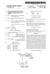
FIG. 1 is a block diagram of a wireless communication
network in which may be implemented some illustrative
embodiments.
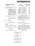
FIG. 2 is a ?ow diagram of a method for site selection in
In conventional systems, a number of communication
channels are also shared amongst a number of users (although
accordance with an illustrative embodiment.
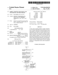
FIG. 3 is a timing diagram used to illustrate a wireless
the number of users per channel is typically much smaller
than in trunked systems). However, there is no control mecha
nism provisioned in the infrastructure to allocate the
45
50
communication unit implementing the site selection method
shown in FIG. 2.
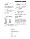
FIG. 4 is a ?ow diagram of a method for site selection in
accordance with an illustrative embodiment.
resources among the users in the system. Thus, in contrast to
a trunked system, each channel in a conventional system is
Skilled artisans will appreciate that elements in the ?gures
dedicated to one or more groups of users enabling the users to 55 are illustrated for simplicity and clarity and have not neces
sarily been drawn to scale. For example, the dimensions of
some of the elements in the ?gures may be exaggerated rela
tive to other elements to help improve understanding of vari
ous embodiments. In addition, the description and drawings
control access to the channels through their radios by manu
ally selecting a channel or selecting a talkgroup that is
assigned a particular channel.
As a user roams or travels in a multi-site communication
system, the user may move from one coverage area served by 60 do not necessarily require the order illustrated. Apparatus and
method components have been represented where appropri
ate by conventional symbols in the drawings, showing only
one repeater of which it is aware to a new coverage area
served by a different repeater of which it may not be aware. In
that case, the user’s radio must be able to detect the repeater
those speci?c details that are pertinent to understanding the
various embodiments so as not to obscure the disclosure with
in the new coverage area to facilitate communications in that
coverage area. In trunked systems, naturally, the control chan
nels can be used to help radios locate a repeater. More par
ticularly, the repeaters periodically send out a message on the
65
details that will be readily apparent to those of ordinary skill
in the art having the bene?t of the description herein. Thus, it
will be appreciated that for simplicity and clarity of illustra
US 8,045,982 B2
3
4
tion, common and well-understood elements that are useful or
repeater. Those skilled in the art will realize that the above
necessary in a commercially feasible embodiment may not be
depicted in order to facilitate a less obstructed view of these
various embodiments.
recognized advantages and other advantages described herein
are merely illustrative and are not meant to be a complete
rendering of all of the advantages of the various embodi
ments.
Referring now to the drawings and in particular to FIG. 1,
DETAILED DESCRIPTION
a conventional wireless communication network 100 is
depicted in which may be implemented some illustrative
Generally speaking, methods for selecting a site in a multi
embodiments. Network 100 comprises sites 110, 120, 130,
site communication system are described with reference to
various embodiments. In accordance with a “passive” site
selection method, a wireless communication device detects a
?rst signal on a channel in the communication system,
wherein the channel is one of a plurality of channels that are
arranged in a ?rst order on a list of channels, and wherein each
of the channels on the list is associated with a different site in
140, and 150 each having at least one repeater located in a
geographic coverage area as indicated by the circles drawn in
the ?gure, wherein all of the repeaters in this illustrative
embodiment are networked together and there is no central
controller for the repeaters as is common in conventional
systems. More particularly, site 110 includes a repeater 112
a multi-site communication system. Upon detecting the ?rst
signal, the device attempts during a ?rst time frame to mea
sure and record signal strength of a signal at each of the
channels on the list based on the ?rst order and beginning with
the detected ?rst signal, and selects as a current home site the
site associated with the channel on the list having the signal
20
that manages at least one channel at site 110. Site 120
includes a repeater 122 that manages at least one channel at
site 120. Site 130 includes a repeater 132 that manages at least
one channel at site 130. Site 140 includes a repeater 142 that
manages at least one channel at site 140. Site 150 includes a
repeater 152 that manages at least one channel at site 150.
with a highest signal strength recorded during the ?rst time
Moreover, each site is associated with a different system
frame. The device then rearranges the channels on the list into
identi?cation such as a color code, a Network Access Code, a
a second order based on the signal strengths recorded during
the ?rst time frame. Accordingly, attempting to measure and
record signal strength for each channel on the channel list is
PL (private line) tone or a DPL (digital private line) word (but
25
uniquely identi?es transmissions from the repeater at the site.
Each repeater in network 100 is capable of operating in an
active repeater mode or de-keying to an inactive sleep mode.
A repeater de-keys when the channel(s) that it manages have
extended to check the rest of the channels on the list after a
signal on one of the channels is detected. This guards against
selecting a home site during a time interval when the repeaters
are each transitioning to an active mode. In another embodi
30
a signal is still present on a channel before the channel’s
signal strength is used as the basis for selecting a home site.
turned off. Further known in the art, de-keyed means that the
repeater’s downlink channel (for repeater to radio transmis
This guards against selecting a home site during a time inter
35
channels on the list is associated with a different site in a
multi-site communication system and is managed by a differ
ent repeater at the associated site, wherein each repeater has
40
an active mode and a sleep mode and is associated with a
known system identi?cation, and wherein the channels on the
list are arranged in a ?rst order beginning with the channel
associated with a current home site. Thereafter, the device
determines to transmit a signal, and beginning with the chan
nel associated with the current home site, when no signal is
detected from the repeater managing the channel and associ
ated with the known system identi?cation, attempts to awake
the repeater from the sleep mode to the active mode, and if the
attempt to awake is successful, uses the repeater to transmit
not been used for radio transmission for some predetermined
period of time. As is known in the art, de-key (and conjuga
tions of “de-key”) means that the repeater’s transmitter is
ment, prior to con?rming a home site, the device con?rms that
val when the repeaters are each transitioning to a sleep mode.
In accordance with an “active” site selection method, a
wireless communication device arranges a plurality of chan
nels on a list during a ?rst time frame, wherein each of the
that will hereinafter be referred to as a color code) that
sions) is inactive while the repeater’s uplink channel (for
radio to repeater transmissions) remains active and available
to detect radio transmissions. When the repeater is de-keyed,
even though the repeater is able to detect transmissions from
the radio, the repeater cannot process and repeat those trans
missions because the radio and the repeater are not synchro
nized. Thus, when the repeater is de-keyed, a radio cannot
utilize the repeater for communications until a) the radio
sends a wakeup message to the repeater which causes the
45
repeater to re-key to the active mode and b) the radio syn
chronizes to the repeater to receive timing information about
the repeater. After the wakeup and synchronization processes
50
are completed, then a radio may ?nally utilize the repeater for
communications.
Further illustrated are radios 114 and 116 operating in site
110, radios 124 and 126 operating in site 120, radio 134
operating in site 130, radio 144 operating in site 140, and
the signal.
radios 154 and 156 operating in site 150. Each radio has
Otherwise, the device selects the next channel in the ?rst
order and when no signal is detected from the repeater man
access to a list of the channels at sites 110 through 150 that the
radio can select for its transmissions and receptions. In an
embodiment, the list is stored in the radio’s memory. In accor
aging the channel and associated with the known color code,
attempts to awake the repeater from the sleep mode to the
active mode, and if the attempt to awake is successful, uses
the repeater to transmit the signal. The device repeats this
process of selecting the next channel in the ?rst order and
55
attempting to transmit on the channel until a ?rst repeater is
60
dance with the teachings herein, the radio implements various
methods to select a home site associated with a channel on the
list and to arrange the channels on the list in an order to
con?rmed as being in the active mode and having the known
system identi?cation or until all of the channels on the list
have been selected at least once. If a repeater is con?rmed as
communicate over an air interface using an air interface pro
tocol that can be either standard or proprietary. One such
being in the active mode and having the known system iden
ti?cation, the device uses the ?rst con?rmed repeater to trans
mit the signal and chooses, as the new home site, the site
associated with the channel managed by the ?rst con?rmed
facilitate the radio quickly ?nding a channel when it needs to
transmit. The home site is the site that the radio will ?rst
attempt to use for its transmissions and receptions.
Since the radios are mobile, the radios and the repeaters
65
standard is a Digital Mobile Radio (DMR) air interface stan
dard, which speci?es various protocols used by two-way
radios (that can both transmit and receive signals) at the data
US 8,045,982 B2
5
6
link layer (i.e., layer 2) of the well known seven-layer Open
Systems Interconnection computer networking model, and
ments described herein, the terms signal, communication and
which is described in ETSI TS (Technical Speci?cation) 102
As such, signals, communications, and transmissions may
361-1 v1.4.5 (2007-12) published by European Telecommu
generically refer to voice, data, or control information relat
ing to network 100. The term call refers to related transmis
sions between radios in network 100.
Moreover, since the repeaters are networked together, at
transmission refer to messages emanating from one device.
nication Standards Institute (ETSI). The ETSI DMR standard
speci?es a two-slot Time Division Multiple Access (TDMA)
structure that transmitting and receiving devices can utilize to
send voice and/or data signals. The voice and data signals are
transmitted in the TDMA slots in accordance with a general
burst format speci?ed in the standard. However, any other
proprietary or standard air interface protocols could be used
in network 100.
In addition, the radios and repeaters can communicate
least one channel managed by each repeater is coupled
together to form a “wide-area channel” on which radios at
different sites can hear the same transmissions. Accordingly,
during each transmission on the wide-area channel, “all sites
light up” so that each repeater is repeating the same signal
while in the active mode. This further means that the repeaters
all transition to the active mode together (although not nec
essarily synchronously from a radio’s perspective) and that
information over a channel using any modulation scheme
including, but not limited to, TDMA (having any slotting
structure), Frequency Division Multiple Access (FDMA),
the repeaters all transition to the sleep mode together (al
Code Division Multiple Access (CDMA), Orthogonal Fre
though not necessarily synchronously from a radio’ s perspec
quency-Division Multiple Access (OFDMA), to name a few.
tive).
As such, those skilled in the art will recognize and appreciate
that the speci?cs of this example are merely illustrative of
20
some embodiments and that the teachings set forth herein are
applicable in a variety of alternative settings. Thus, since the
teachings described do not depend on the environment, they
repeater in order to perform the method. The radio simply
can be applied to any type of wireless communication net
work or system having any number sites, repeaters and radios,
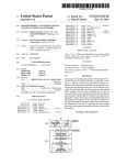
FIG. 2 is a ?ow diagram of a method 200 performed by a
radio for passive site selection in accordance with an illustra
tive embodiment. The site selection method is deemed “pas
sive” because the radio is not required to send messages to the
passively scans the channels in its channel list in an attempt to
25
detect and measure signal strength of signals on the channels
wherein the radios have access to a list of the channels that can
in order to select a home site based on these measurements.
be used at the various sites in the network.
The channels in the channel list are arranged in a given order
Referring again to FIG. 1, each repeater and radio is at least
equipped with a transceiver (i.e., transmitter and receiver
apparatus), a memory and a processing device and is further
at the start of each passive channel scan with a channel asso
30
equipped with any additional components as needed for a
commercial embodiment. The transceiver, memory and pro
cessing device can have any suitable physical implementation
and are topologically coupled depending on the particular
device implementation. These components are further opera
35
reference to FIG. 4.
In an embodiment that that does not interfere with the
40
radio’s transmission of signals or reception of signals of
interest, the radio performs method 200 when (202) the radio
is not in a call, i.e., actively transmitting signals or actively
receiving a signal of interest. Moreover, in an embodiment
that facilitates power saving in the radio, the radio does not
tively coupled and can be adapted, arranged, con?gured, and
designed to perform methods in accordance with the teach
ings herein, for example, as illustratively described by refer
ence to FIG. 2 through FIG. 4.
As referred to herein, a radio includes, but is not limited to,
devices commonly referred to as wireless communication
devices, access terminals, mobile radios, mobile stations,
subscriber units, user equipment, mobile devices, or any other
device capable of operating in a wireless environment, and
are referred to herein simply as radios. Examples of radios
include, but are not limited to, two-way radios, mobile
45
phones, cellular phones, Personal Digital Assistants (PDAs),
laptops and two-way pagers. As used herein, a repeater is a
50
sured for a signal detected on its home site channel falls below
a known threshold. In another illustrative implementation, the
radio receives periodic beacon messages on its home site
channel, and the radio starts the passive scan when the signal
strength of the beacon messages falls below the threshold or
55
when the radio fails to receive a beacon message within a
information in signals to one or more radios via a communi
cation link. A repeater includes, but is not limited to, equip
ment commonly referred to as infrastructure devices, base
radios, base stations, base transceiver stations, access points,
routers or any other type of infrastructure equipment inter
facing a wireless communication device in a wireless envi
ronment, and is referred to herein simply as a repeater.
As mentioned earlier, the devices in network 100 commu
nicate using communication links (also referred to herein as
channels). The channels are the physical communication
certain time period, which indicates that the radio has moved
outside of the coverage area of its current home site.
60
example, radio 114 is operating in its home site 110 and
implementing method 200. Accordingly, radio 114 has stored
within network 100 and can comprise wired links or wireless
links. If the channels comprise wireless links, the correspond
ing physical resource is an allocation of radio spectrum that is
lated by a media or control stream. As it relates to the embodi
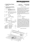
A radio’s performance of the passive channel scan method
200 is next described by reference to a timing diagram 300
illustrated in FIG. 3, where time is increasing from left to right
as indicated by the direction of the arrow at the end of the time
line at the bottom of FIG. 3. For purposes of this illustrative
resources over which information is sent between the devices
partitioned into radio frequency (RF) carriers that are modu
continuously perform method 200 even when it is not in a call
but has some internal policy for when and how often it per
forms the passive channel scan. For example, the radio starts
(204) a passive channel scan only upon expiration of a timer
set by the radio at the conclusion of a call and at the conclu
sion of every passive channel scan. Alternatively, or in addi
tion, the radio monitors the channel at its home site (also
referred to herein as its “home site channel”) and starts (204)
the passive channel scan when (202) the signal strength mea
device that is a part of a ?xed network infrastructure and can
receive information (either control or media, e.g., data, voice
(audio), video, etc.) in a signal from a radio and transmit
ciated with the radio’s current home site being the ?rst chan
nel in the given order. Results of each passive scan are further
used to rearrange the order of the channel list for use in
performing an active site selection method in accordance with
another embodiment of the teachings herein as illustrated by
65
in its memory a channel list that includes channels labeledA
(its current home site channel), B, C, D, and E managed
respectively by repeaters 112, 122, 132, 142, 152. The chan
US 8,045,982 B2
7
8
nels in the channel list are arranged in the order A, C, D, B,
and E. Upon determining to start (204) the passive channel
scan, radio 114 tunes to the radio frequency of channel A (its
home site channel) and scans the channel to determine (206)
Commission rules, which should be avoided. Verifying the
color code helps to prevent such illegal transmissions. The
format of the SYNC message depends on the particular pro
tocols being used in the network. In a DMR system, for
example, the SYNC is included in a 48 bit ?eld in the center
of some TDMA bursts, and the color code can be found in the
Slot Type ?eld in data bursts and in the EMB ?eld in voice
bursts.
If SYNC is not present in the signal (e.g., as in the case of
an analog signal) or if the SYNC contains an unknown color
code (e.g., due to errors when decoding the color code) or an
incorrect color code (one that doesn’t match the known color
whether a signal is present. Radio 214 uses its transceiver to
perform the channel scan and signal detection using any
known techniques.
If no signal is detected (206), radio 114 selects (216) and
scans the next channel in the order of the channel list to
determine (206) whether a signal is present. Radio 114 con
tinues this channel selection and channel scan loop until a
signal is detected or until it determines (214) that all channels
have been scanned on the list, at which point radio 114 per
forms (220) a channel sort, which includes selecting or choos
ing a home site and determining the channel order of the
channel list.
Turning momentarily to FIG. 3, radio 114 performs a ?rst
passive channel scan 310 during a ?rst time frame. During
this passive channel scan, the radio sequentially scans all ?ve
channels in the given order (i.e., A, C, D, B, E) at the start of
code for the channel), radio 114 proceeds to select (216) and
scan the next channel in the list. In this illustrative example,
the SYNC is present and the color code matches, so radio 114
measures and records (210) the signal strength of the signal
on channel B. This can be done using any suitable method
including, but not limited to, an average Received Signal
20
the passive channel scan but fails to detect (206) a signal on
any of the channels because all of the respective repeaters
112, 132, 142, 122, and 152 are in the sleep mode. At the
conclusion of the passive channel scan 310, during a channel
sort 312, radio 114 maintains site 112 associated with channel
25
A as its current home site and maintains the channel order A,
C, D, B, E of the channel list for the next passive channel scan.
It should be noted that during the channel sort, “selecting”
or “choosing” a home site includes both maintaining the
current home site as the “new” home site and selecting a
completely different home site as the new home site. In addi
strength measurement, to name a few. Signal strength is illus
trated in FIG. 3 by the height of a bar above the channel labels
at the bottom of the drawings. The radio 114 also quali?es the
signal to determine (212) whether is it a call of interest, for
instance by determining whether it is addressed to the radio or
to a group to which the radio belongs. If the call is of interest,
radio 114 processes (218) the call and performs (220) the
channel sort, which includes selecting as the new home site,
home site 122 associated with channel B. Radio 114 further
30
rearranges the channel order by placing channel B at the top
of the order. The remaining channels can retain their current
relative channel order. Thus for the initial channel order A, C,
D, B, E, the new channel order could be B, A, C, D, E.
tion, “rearranging” the order of the channels on the channel
list includes both maintaining the current order of the chan
nels and actually changing the order to a different order.
Moreover, in this embodiment the home site channel was
Strength Indication (RSSI), signal-to-noise (SNR) ratio, local
mean signal strength measurement, logarithmic signal
35
If the signal on channel B is not of interest, as in this case,
radio 114 scans all of the remaining channels on its channel
scanned only once during the passive channel scan. However,
list in the current channel order (i.e., E, A, C, D) and then
in another embodiment, the radio can use the home site chan
nel as a “priority channel” and alternately scan the home site
channel with each other channel in the list. This enables the
performs a channel sort 322. Since the signal on channel B
radio to remain on the priority channel during half of the
was the ?rst signal detected (222) during the passive channel
scan 320, scanning all of the remaining channels on the chan
40
nel list, in this case, comprises “extending” the passive chan
channel scan time frame so as not to miss any signal of interest
nel scan to rescan some of the channels (e.g., A, C, and D) to
on the home site channel while performing the passive chan
afford radio 114 a better opportunity to perform the scanning
when all repeaters are in the active mode. Extending the
passive channel scan in this manner essentially has the effect
of restarting (224) the passive channel scan after the ?rst
detected signal to scan all other remaining channels on the
channel list.
During the extended passive channel scan 320, radio 114
nel scan.
During a subsequent passive channel scan 320 over a sub
sequent time frame, radio 114 scans the channels in the cur
45
rent order (A, C, D, B, E) beginning with its home site channel
A. During this passive channel scan, the repeaters begin to
re-key from a sleep mode 302 to an active mode 304 (begin
ning with repeater 132) in order to repeat a signal, and radio
114 detects (206) the signal on channel B. Although the
repeaters re-key at substantially the same time, the re-keying
appears asynchronous from the radio’s perspective due to
various propagation delays through the backend and RF chan
nels, as can be seen in FIG. 3 by the different transition times
from sleep mode to active mode for some of the repeaters.
50
determining the channel having a signal with the highest
measured and recorded signal strength (in this case channel
B, since it has the tallest signal strength bar, followed by
channels C thenA); selecting channel B as the new home site;
55
Upon detecting the signal, the radio determines (208) if a
synchronization message (SYNC) is present in the signal and
if so detects the color code from the signal to see if it matches
a known color code for the associated site (site 122 in this
case). Checking the color code enables the radio 114 to con
?rm that it has detected a channel managed by a repeater with
which it is authorized to operate since there may be a number
unauthorized repeater results in an “illegal” transmission, for
instance under the United States Federal Communication
and rearranging the channels on the list into a new order for
the next passive channel scan based on the measured and
recorded signal strengths. In this case, the channels are rear
ranged into the order B, C, A, D, E.
In a further embodiment, before selecting a new home site
60
and rearranging the order of the channels on the channel list,
radio 114 con?rms (324) that a signal is still present on the
channel having the highest recorded signal strength. This
of other repeaters (not shown) in the network 100 with which
the radio is not authorized to operate but that manage a chan
nel at the same frequency. Attempting to transmit using an
also measures and records average RSSI for channels A and
C. Moreover, the channel sort 322 in this case comprises:
65
prevents the radio from detecting that a channel has the high
est signal strength only because the passive channel scan is
being performed during a time frame when some of the
repeaters have de-keyed to the sleep mode and some are in the
active mode in the process of de-keying. In this case, radio
US 8,045,982 B2
10
114 con?rms (324) that a signal still exists on channel B, and
thereby selects site 112 as its current home site and rearranges
the channels on the list into the order B, C, A, D, E based on
method. For purposes of consistency and ease of understand
ing, radio 114 is described as also performing the method 400.
Method 400 starts upon radio 114 determining that a signal
the signal strengths measured and recorded during the passive
is ready (402) for transmission by the radio. The signal is any
channel scan 320.
type of transmit request generated in the radio as a result of,
for example, a user of radio 114 pushing a push-to-talk (PTT)
During a subsequent passive channel scan 330 in the chan
nel order B, C, A, D, E over a subsequent time frame, radio
114 measures and records average RSSI for channels B, C,
button to send audio, a user manual selection such as the user
pressing a button on the radio or using some other user inter
andA and detects during a channel sort 332 that channel B is
face (e. g., selecting a menu item) to manually start the active
again associated with the highest signal strength followed by
site selection process, etc ., the user requesting to send data via
channels C then A. Upon radio 114 con?rming (334) that a
signal remains on channel B, the radio retains site 122 (asso
ciated with channel B) as its home site and retains the channel
order B, C, A, D, E based on the measured and recorded RS Sl.
During a subsequent passive channel scan 340 in the chan
nel order B, C, A, D, E over a subsequent time frame, radio
114 measures and records average RSSI for channels B, C,
a user interface, the radio being programmed to periodically
send location data, etc. Radio 114 obtains the channel list
which has a given order, which in this embodiment is the
andA and detects during a channel sort 342 that channel C is
has an order that is determined in any suitable manner, such as
order C, B, A, D, E generated during the last passive site
selection scan 370, and selects (404) a ?rst channel from the
list (which in this case is the home site channel C) to start the
active channel scan. In another embodiment, the channel list
associated with the highest signal strength followed by chan
nels B and A. Upon radio 114 con?rming (344) that a signal
remains on channel C, the radio selects site 132 (associated
a preprogrammed order.
20
25
determine (406) whether a signal is present. If no signal is
present, radio 114 sends a message (proprietary or standard)
to repeater 132 in an attempt (412) to awaken its repeater. If
the repeater con?rms that it is awake, e.g., via some acknowl
edgement message, radio 114 can synchronize to the repeater
and transmit (410) signals on channel C. If radio 114 is unable
to awaken repeater 132, it determines (416) if it has traversed
30
all channels on the channel list.
If all channels on the channel list have been traversed
(either scanned or skipped) at least once (i.e., at least one full
with channel C) as its new home site and rearranges the
channel order to C, B, A, D, E based on the measured and
recorded RSSI.
During a subsequent passive channel scan 350 in the chan
nel order C, B, A, D, E over a subsequent time frame, the
repeaters begin de-keying to the sleep mode, and the radio
114 only measures and records an average RSSI for channel
B, which by default has the highest recorded signal strength.
However, when the radio 114 attempts to con?rm (354) a
Upon selecting the home site channel C, radio 114 tunes to
the radio frequency of the channel and scans the channel to
channel on channel B during a channel sort 352, the radio no
longer detects a signal on channel B. Therefore radio 114
scan cycle was completed), radio 114 ends (420) the active
retains its current home site 132 and retains the current chan
channel scan and noti?es a user that the active channel scan
nel order C, B, A, D, E for the next passive channel scan.
Similar to the re-keying process, the repeaters de-key at sub
stantially the same time. However, the de-keying appears
asynchronous from the radio’s perspective due to various
propagation delays through the backend and RF channels, as
can be seen in FIG. 3 by the different transition times from
active mode to sleep mode for some of the repeaters.
was unsuccessful, e.g., because of an unsuccessful attempt to
35
40
During a subsequent passive channel scan 360 in the chan
nel order C, B, A, D, E over a subsequent time frame, radio
114 fails to detect a signal on any of the channels on its
channel list since all of the repeaters are in the sleep mode.
Therefore, during a channel sort 362, the radio retains its
current home site 132 and retains the current channel order C,
45
and continues method 400 by scanning (406) channel B and
performing signal detection (408) and a color code compari
B, A, D, E for the next passive channel scan. Likewise, during
a subsequent passive channel scan 370 in the channel order C,
B, A, D, E over a subsequent time frame, radio 114 fails to
detect a signal on any of the channels on its channel list since
send audio or data, because no awake repeater having the
correct color code was found, etc. This noti?cation may be
some type of indication, e.g., a tone, a message on a display,
etc., that the radio is out of range if radio 114 was unable to
detect a signal on any of the channels or channel busy where
the radio 114 skipped scanning one or more of the channels
because a signal was detected on the channel. Moreover, the
radio may perform more than one active scan cycle before
providing (420) a failure noti?cation to the user. If all chan
nels on the list have not been traversed, radio 114 selects (418)
the next channel in the channel order (in this case channel B
son (408) to determine whether it can transmit (410) on this
50
all of the repeaters remain in the sleep mode. Therefore,
channel.
If as a result of scanning channel C, radio 114 detects a
signal on the channel, the radio detects SYNC and attempts to
during a channel sort 372, the radio retains its current home
detect color code from the signal and determines (408)
site 132 and retains the current channel order C, B, A, D, E for
whether a detected color code matches the known color code
corresponding to channel C. If there is a color code match,
the next passive channel scan.
A bene?t of performing a passive channel scan is that it
results in an ordering of the channels on a radio’ s channel list
with the channels at the top of the order being those corre
55
radio 114 fails to detect a color code, detects an unknown
color code, or the detected color code fails to match the
sponding to sites associated with the highest signal strengths
and, therefore, the most likely sites for the radio to success
fully start a call. This reduces the time to ?nd a repeater if the
60
ordering of channels resulting from the passive channel scan
is used during an active channel scan or active site selection
method. FIG. 4 is a ?ow diagram of a method 400 for “active”
site selection in accordance with an illustrative embodiment.
Method 400 is deemed an “active” site selection method
because the radio may attempt to awaken one or more repeat
ers to the active mode during the course of performing the
radio 114 knows that it has detected a channel managed by
repeater 132 that it can use to transmit (410) its signals. If
65
known color code, the radio follows its internal policy for
politeness (414) if it has one. If the radio has no politeness
policy or if the radio’s politeness policy is impolite to all or
polite to its own color code only, then the radio attempts (412)
to awaken its repeater and if successful uses the repeater for
its transmissions.
If radio 114 is unable to awaken (412) its repeater or if its
politeness policy (414) is polite to all, the radio skips attempt
ing to awaken its repeater associated with the current selected
US 8,045,982 B2
11
12
channel and determines (416) if it has traversed all channels
on the channel list. The radio further either ends (420) the
that comprises, has, includes, contains a list of elements does
not include only those elements but may include other ele
active channel scan and noti?es a user that the active channel
scan was unsuccessful or continues (418) the active channel
scan with the next channel in the channel order. If as a result
of the active channel scan, radio 114 selects a channel on
ments not expressly listed or inherent to such process,
which to transmit (410), the site associated with this channel
is made the current home site, if it is not already the home site.
of additional identical elements in the process, method,
method, article, or apparatus. An element proceeded by
“comprises . . . a”, “has . . . a”, “includes . . . a”, “contains . .
. a” does not, without more constraints, preclude the existence
article, or apparatus that comprises, has, includes, contains
In this case, the radio transmits if there is no signal detected on
the element. The terms “a” and “an” are de?ned as one or
the channel (but the repeater is keyed); the radio is provi
sioned with impolite access irrespective of whether any signal
more unless explicitly stated otherwise herein. The terms
“substantially”, “essentially”, “approximately”, “about” or
is detected on the channel; or the radio is partied to the call
any other version thereof, are de?ned as being close to as
that is active on the channel, and its politeness policy allows
impolite behavior during a call to which it is partied.
Moreover, in an embodiment, upon the user requesting a
manual active site scan, the method 400 begins at the channel
with which the previous active channel scan ended, which
many times is the channel associated with the current home
site. In addition, after the radio awakens a repeater during a
manual active site scan, the radio can be programmed to wait
understood by one of ordinary skill in the art, and in one
non-limiting embodiment the term is de?ned to be within
10%, in another embodiment within 5%, in another embodi
ment within 1% and in another embodiment within 0.5%. The
term “coupled” as used herein is de?ned as connected,
although not necessarily directly and not necessarily
20
for a predetermined duration (e. g., l 5 seconds) before starting
an active channel scan to provide the user time to lock the
radio to the corresponding channel.
In yet another embodiment as brie?y mentioned above, the
user can lock and unlock the radio to the current home site
25
channel, e.g., through a programmable button or menu in
order to prevent the radio from performing a passive channel
scan. This is useful when the user stays within a site, and the
radio has determined the correct home site channel for its
communications. Locking the radio to the current home site
channel optimizes call reception performances as well as
mechanically. A device or structure that is “con?gured” in a
certain way is con?gured in at least that way, but may also be
con?gured in ways that are not listed. Also, the sequence of
steps in a ?ow diagram or elements in the claims, even when
preceded by a letter does not imply or require that sequence.
The Abstract of the Disclosure is provided to allow the
reader to quickly ascertain the nature of the technical disclo
sure. It is submitted with the understanding that it will not be
used to interpret or limit the scope or meaning of the claims.
In addition, in the foregoing Detailed Description, it can be
battery life. In addition, the radio is able to spend more time
seen that various features are grouped together in various
embodiments for the purpose of streamlining the disclosure.
This method of disclosure is not to be interpreted as re?ecting
in a low power mode when operating in the locked state since
it ceases to perform passive channel scans.
an intention that the claimed embodiments require more fea
tures than are expressly recited in each claim. Rather, as the
In yet another embodiment, the radio does not attempt to
awaken a particular repeater if the radio is attempting to send
data and the radio has unsuccessfully attempted to awaken
repeaters within a certain time frame (e.g., 30 seconds). This
30
35
following claims are hereby incorporated into the Detailed
Description, with each claim standing on its own as a sepa
rately claimed subject matter.
limits unwanted inbound transmissions, especially when the
radio is out of the coverage area of the multi-site communi
40
cation system and is attempting to send periodic data like
We claim:
1. A method for selecting a home site while roaming in a
location updates.
In the foregoing speci?cation, speci?c embodiments have
been described. However, one of ordinary skill in the art will
appreciate that various modi?cations and changes can be
made without departing from the scope of the invention as set
multi-site communication system, the method comprising:
45
forth in the claims below. Accordingly, the speci?cation and
?gures are to be regarded in an illustrative rather than a
restrictive sense, and all such modi?cations are intended to be
included within the scope of present teachings. The bene?ts,
advantages, solutions to problems, and any element(s) that
50
detecting a ?rst signal on a channel in the communication
system, wherein the channel is one of a plurality of
channels that are arranged in a ?rst order on a list of
channels, and wherein each of the channels on the list is
associated with a different site in a multi-site communi
cation system;
upon detecting the ?rst signal, attempting during a ?rst
time frame to measure and record signal strength of a
signal at each of the channels on the list based on the ?rst
may cause any bene?t, advantage, or solution to occur or
become more pronounced are not to be construed as a critical,
required, or essential features or elements of any or all the
claims. The invention is de?ned solely by the appended
claims including any amendments made during the pendency
following claims re?ect, inventive subject matter lies in less
than all features of a single disclosed embodiment. Thus the
order and beginning with the detected ?rst signal;
selecting as a current home site, the site associated with the
55
of this application and all equivalents of those claims as
issued.
Moreover in this document, relational terms such as ?rst
channel on the list having the signal with a highest signal
strength recorded during the ?rst time frame; and rear
ranging the channels on the list into a second order based
on the signal strengths recorded during the ?rst time
frame;
to distinguish one entity or action from another entity or
attempting during a second time frame subsequent to the
?rst time frame to measure and record signal strength of
action without necessarily requiring or implying any actual
a signal at each of the channels on the list based on the
such relationship or order between such entities or actions.
second order and beginning with the channel associated
with the current home site;
and second, top and bottom, and the like may be used solely
The terms “comprises,” “comprising,” “has”, “having,”
“includes”, “including,” “contains”, “containing” or any
other variation thereof, are intended to cover a non-exclusive
inclusion, such that a process, method, article, or apparatus
60
65
determining the channel from the list having the signal with
a highest signal strength recorded during the second
time frame; determining whether the signal with the
US 8,045,982 B2
14
13
highest signal strength recorded during the second time
10. The method of claim 7, wherein the attempting to
awake is performed according to a rule of politeness compris
ing one of:
attempting to awake the repeater only if no signal is
frame can still be detected at a subsequent time to the
second time frame;
if the signal with the highest signal strength recorded dur
ing the second time frame can still be detected, then
detected on the channel:
selecting as a new home site, the site associated with the
attempting to awake the repeater even if a signal from a
channel having the signal with the highest signal
strength recorded during the second time frame, and
repeater having an unknown system identi?cation, an
incorrect system identi?cation, or no system identi?ca
rearranging the channels on the list into a third order
tion is detected on the channel; or
based on the signal strengths recorded during the second
attempting to awake the repeater irrespective of whether
time frame.
2. The method of claim 1, wherein the attempting to mea
sure and record during the second time frame is performed
after the signal strength measured for a signal at the channel
associated with the current home site falls below a signal
any signal is detected on the channel.
11. The method of claim 7, wherein the attempting to
awake a repeater is a result of a manual user selection.
12. A method for selecting a home site while roaming in a
multi-site communication system, the method comprising:
strength threshold.
3. The method of claim 1, wherein the attempting to mea
sure and record signal strength during the ?rst and second
time frames is performed by a wireless communication
device that is not participating in a call on any of the channels
20
on the list.
4. The method of claim 1, wherein the new home site is
selected only if the signal strength recorded for the signal at
its associated channel exceeds by a threshold the signal
strength recorded for the signal at the channel associated with
attempting during a second time frame subsequent to the
?rst time frame to measure and record signal strength of
25
sure and record during the second time frame is performed
after a beacon message is not received on the channel asso
30
6. The method of claim 1, wherein the measured signal
strengths are recorded for the detected signals that include a
method further comprising:
a) determining to transmit a signal;
b) beginning with the channel associated with the current
frame;
if the signal with the highest signal strength recorded dur
35
selecting as a new home site, the site associated with the
re-arranging the channels on the list into a second order
40
multi-site communication system, the method comprising:
45
c) otherwise selecting the next channel in the second order
and when no signal is detected from the repeater man
50
signal;
55
as being in the active mode and having the known system
identi?cation or until all the of the channels on the list
have been selected at least once.
8. The method of claim 7 further comprising:
using the ?rst con?rmed repeater to transmit the signal; and
selecting, as the new home site, the site associated with the
channel managed by the ?rst con?rmed repeater.
9. The method of claim 7 further comprising providing an
indication to a user of a failure to transmit if all of the channels
on the list have been selected at least once without a repeater 65
being con?rmed as being in the active mode and having the
known system identi?cation.
a) arranging a plurality of channels on a list during a ?rst
time frame, wherein each of the channels on the list is
associated with a different site in a multi-site communi
transmit the signal;
d) otherwise, repeating c) until a ?rst repeater is con?rmed
based on the signal strengths recorded during the second
time frame.
13. A method for selecting a home site while roaming in a
system identi?cation, attempting to awake the repeater
aging the channel and associated with the known system
identi?cation, attempting to awake the repeater from the
sleep mode to the active mode, and if the attempting to
awake is successful, using the repeater to transmit the
ing the second time frame can still be detected, then
channel having the signal with the highest signal
strength recorded during the second time frame, and
home site, when no signal is detected from the repeater
managing the channel and associated with the known
from the sleep mode to the active mode, and if the
attempting to awake is successful, using the repeater to
strength recorded during the second time frame;
determining whether the signal with the highest signal
strength recorded during the second time frame can still
be detected at a subsequent time to the second time
repeater synchronization and an expected system identi?ca
tion.
7. The method of claim 1, wherein each channel on the list
is managed by a different repeater at the associated site, and
wherein each repeater has an active mode and a sleep mode
and is associated with a known system identi?cation, the
a signal at each of the channels on the list based on the
?rst order and beginning with the channel associated
with the current home site; determining the channel
from the list having the signal with a highest signal
the current home site.
5. The method of claim 1, wherein the attempting to mea
ciated with the current home site for a ?rst time period.
arranging a plurality of channels on a list during a ?rst time
frame, wherein each of the channels on the list is asso
ciated with a different site in a multi-site communication
system, and wherein the channels on the list are arranged
in a ?rst order beginning with the channel associated
with a current home site;
cation system and is managed by a different repeater at
the associated site, wherein each repeater has an active
mode and a sleep mode and is associated with a known
system identi?cation, and wherein the channels on the
list are arranged in a ?rst order beginning with the chan
nel associated with a current home site;
b) determining to transmit a signal;
c) beginning with the channel associated with the current
home site, when no signal is detected from the repeater
managing the channel and associated with the known
system identi?cation, attempting to awake the repeater
from the sleep mode to the active mode, and if the
attempting to awake is successful, using the repeater to
transmit the signal;
d) otherwise selecting the next channel in the ?rst order and
when no signal is detected from the repeater managing
the channel and associated with the known system iden
ti?cation, attempting to awake the repeater from the
sleep mode to the active mode, and if the attempting to
awake is successful, using the repeater to transmit the
signal;
US 8,045,982 B2
15
16
e) otherwise, repeating d) until a ?rst repeater is con?rmed
the ?rst con?rmed repeater to transmit the signal; and
as being in the active mode and having the known system
identi?cation or until all the of the channels on the list
have been selected at least once;
i) upon con?rming the ?rst repeater as being in the active 5
selecting as the new home the site associated with the
channel managed by the ?rst con?rmed repeater.
mode and having the known system identi?cation, using
*
*
*
*
*
UNITED STATES PATENT AND TRADEMARK OFFICE
CERTIFICATE OF CORRECTION
PATENT NO.
: 8,045,982 B2
APPLICATION NO.
: 12/253478
: October 25, 2011
: Khoo et al.
DATED
INVENTOR(S)
Page 1 of 1
It is certified that error appears in the above-identi?ed patent and that said Letters Patent is hereby corrected as shown below:
In Column 13, Line 57, in Claim 7, delete “all the” and insert -- all --, therefor.
In Column 14, Line 5, in Claim 10, delete “channel:” and insert -- channel; --, therefor.
In Column 15, Line 3, in Claim 13, delete “all the” and insert -- all --, therefor.
In Column 16, Line 2, in Claim 13, delete “home the” and insert -- home --, therefor.
Signed and Sealed this
Eighteenth Day of December, 2012
.
David J. Kappos
Director 0fthe United States Patent and Trademark O?ice