1
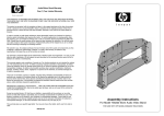
Use & Care Guide Drying cabinet Save these instructions for future reference ASKO DC 7171 Dear ASKO customer! Congratulations on your excellent product choice and welcome to the Asko family. A global family with its roots in Scandinavia. Good results, design, low environmental impact (both on nature and in your home), user-friendliness, low consumption of time, energy and water, long service life, reliability.... Good appliances should include all of these. And this is what we try to give you. When you buy an ASKO product, we want you to feel assured that the inside is as good as the outside, and that the ethics and morals on which we built this machine are just as high as the quality and performance you get from it. That is what Scandinavian quality is all about. In order to get the best possible results from your drying cabinet, please read this manual before using the appliance. And if you have any questions, please do not hesitate to contact us by the phone or via our website. Best regards from Scandinavia and the people at Asko. Contents Important safety instructions . . . . . . . . 4 Symbols . . . . . . . . . . . . . . . . . . . . . 4 Important safety information . . . . . . 4 Description of the drying cabinet . . . . 5 Control panel . . . . . . . . . . . . . . . . . . . . . 6 Location requirements . . . . . . . . . . . . . 7 Electrical requirements . . . . . . . . . . . . . 8 User liability. . . . . . . . . . . . . . . . . . . 8 Electrical connection . . . . . . . . . . . . 8 Grounding instructions . . . . . . . . . . 8 Ventilation requirements. . . . . . . . . . . . 9 Ventilation out into the room where the drying cabinet is located . . . . . . 9 Connection to a vent duct . . . . . . . 10 Installation instructions . . . . . . . . . . . 12 Unpacking drying cabinet . . . . . . . 12 A complete delivery includes . . . . 12 Recommended tools . . . . . . . . . . . 12 Reverse door swing. . . . . . . . . . . . 13 Level drying cabinet . . . . . . . . . . . 14 Attaching drying cabinet to wall . . . . 14 Mounting into custom cabinetry. . . . 15 Ventilation connection . . . . . . . . . . 17 Electrical connection . . . . . . . . . . . 17 Final inspection . . . . . . . . . . . . . . . 18 Operation instructions . . . . . . . . . . . . 19 Starting your drying cabinet . . . . . 19 Pausing or restarting. . . . . . . . . . . 19 Stopping your drying cabinet . . . . 19 Loading . . . . . . . . . . . . . . . . . . . . . 19 Cycle and drying tips. . . . . . . . . . . 20 Cycles . . . . . . . . . . . . . . . . . . . . . . 21 Care. . . . . . . . . . . . . . . . . . . . . . . . . . . . 22 Cleaning the drying cabinet . . . . . 22 When the drying cabinet is not in use . . . . . . . . . . . . . . . . . . . . . . . . 22 Troubleshooting. . . . . . . . . . . . . . . . . . 23 Service and Warranty . . . . . . . . . . . . . 24 Technical data . . . . . . . . . . . . . . . . . . . 26 Technical characteristics . . . . . . . . 26 Exhaust . . . . . . . . . . . . . . . . . . . . . 26 Energy consumption and drying times . . . . . . . . . . . . . . . . . . . . . . 26 Manufacturing standards. . . . . . . . 26 Installation spacing for custom cabinetry . . . . . . . . . . . . . . . . . . . . 26 Personal notes . . . . . . . . . . . . . . . . . . . 27 This user manual The contents of this user manual describe the drying cabinet’s: Function Use and contains instructions for: Installation Maintenance Date: November 2005 Customer Care Center 1-800-898-1879 www.askousa.com 3 Important safety instructions Read this manual carefully and follow the provided instructions. Symbols Warning! Advice and instructions for how the product is best used for problem-free operation Indicates risk for injury (including fatal injury) or serious damage to the product if the instructions are not observed. Important safety information The following advice and warnings are included to help you avoid incorrect operation and unnecessary risks for accidents. You must therefore read the manual carefully prior to installation and use of the drying cabinet. Read this user manual prior to operating the drying cabinet. Do not dry clothing or similar articles that have recently been subjected to gasoline or other volatile and flammable liquids. This can result in the formation of an explosive gas mixture. Do not allow children to play in or on the drying cabinet. Keep an eye on children close to the drying cabinet. Follow Asko’s instructions when making repairs or replacing parts. If softeners or anti-static agents are used, follow the manufacturer’s instructions for use. Never use heat in the cabinet for products that contain foam rubber or similar materials. Carefully follow the manufacturer’s instructions for washing and drying of such products. Keep the area around the outlet duct free from dust and dirt. Periodically clean the inside of the drying cabinet. The drying cabinet is to be installed or stored indoors. Always keep this manual accessible for future reference. 4 This manual does not cover every possible conditions and situation that can occur. Use common sense and caution when installing, operating, and maintaining any appliance. Customer Care Center 1-800-898-1879 www.askousa.com Description of the drying cabinet 9 1 10 X DC XXX 2 3 4 11 5 12 6 13 7 8 1. 2. 3. 4. 5. 6. 7. 8. Exhaust collar Drying cabinet model Hanger hooks Rating plate (inside) Upper hanger section Middle hanger section Lower hanger section Shoe rack Customer Care Center 1-800-898-1879 www.askousa.com 9. 10. 11. 12. 13. Air intake Control panel Door Door hanger for lighter articles Glove hanger 5 Control panel 1 1. 2. 3. 6 2 3 Temperature setting Timer START button Customer Care Center 1-800-898-1879 www.askousa.com Location requirements If the drying cabinet is to be installed with a connection to exhaust air ventilation, this must be available on the premises. A grounded electrical outlet must be within 79 in. (2 meters) of the drying cabinet’s upper section. A 79-in. (2-meter) grounded power cord with a plug is connected at the top of the drying cabinet. If the electrical outlet is not located as above, the location must be adjusted so that an extension cord is not necessary. The electrical outlet shall be easily accessible after installation of the drying cabinet. Take this into consideration even in cases when the drying cabinet is built into custom cabinetry or similar framing. For further information, see the section “Electrical requirements”. The floor must be able to support the weight of the cabinet 133 lbs (60 kg). The floor must be flat with a slope under the cabinet of no more than 1 in. (2.5 cm). The drying cabinet is only intended for installation indoors and at temperatures above 0°C (32°F). The drying cabinet may not be located in environments where pressurized water is used for cleaning. Customer Care Center 1-800-898-1879 www.askousa.com Installation dimensions 23 7/16” (59.5 cm) 25 1/4” (64.0 cm) 68 1/8” (173.0 cm) 24” (61.0 cm) 7 Electrical requirements User liability Warning! It is the responsibility of the user to contact an authorized electrician if an electrical outlet in compliance with this manual is unavailable. Electrical connection Connect to grounded wall outlet Do not remove ground connection Do not use an adapter Do not extend the cord Failure to observe the above entails risk for serious injury or fire. Grounding instructions The drying cabinet must be connected to a 110 V, single-phase, 60 Hz grounded wall outlet. The drying cabinet is delivered ready for connection with a 79-in. (2-meter) power cord with a grounded plug. The drying cabinet is to be connected with the supplied power cord to a grounded wall outlet and may not be wired to terminals. The electrical outlet shall be located so that the power plug can be easily unplugged without moving the unit. Check that the power source is in agreement with the data on the rating plate and that the wiring is properly grounded in compliance with applicable standards. We recommend that the wiring be installed with a circuit breaker. The connection shall be separately fused. The manufacturer bears no liability if the electrical connection is not made as specified in this user manual. 8 Risk for electrocution This drying cabinet must be properly grounded. In the event of malfunction or breakdown, grounding will reduce the risk of electric shock by providing a path of least resistance for electric current. WARNING Improper connection can result in a risk of electric shock. Check with a qualified electrician or service representative or personnel if you are in doubt as to whether the drying cabinet is properly grounded. Do not modify the plug provided with the drying cabinet. If it will not fit the outlet, have a proper outlet installed by a qualified electrician. Customer Care Center 1-800-898-1879 www.askousa.com Ventilation requirements Moist air can be discharged in two ways: Ventilation out into the room where the drying cabinet is located Connection to a vent duct (exhaust air ventilation) Ventilation out into the room where the drying cabinet is located It is advisable to open a door or window in the room for optimal ventilation. When the drying cabinet is built in, the supplied vent hose (only certain markets) is replaced by a solid vent pipe with a diameter of 4 in.(10.2 cm). The vent pipe should not exceed 3 ft (91.4 cm) in length. The distance between the vent pipe’s upper edge and the ceiling must not be less than 1 foot (30 cm). The vent pipe must extend beyond the enclosing cabinet work. Provide appropriate air supply to the drying cabinet’s air intake. 1. 2. Moist air out Air intake Top Minimum 1 ft (30 cm) Top 1 Minimum 1 ft (30 cm) Ventilation out into the room where the drying cabinet is located. Drying cabinet not built in Customer Care Center 1-800-898-1879 2 2 1 www.askousa.com Ventilation out into the room where the drying cabinet is located. Built-in drying cabinet in custom cabinetry 9 Connection to a vent duct When the cabinet is on, 45 m³ (1590 cubic ft) of moist air is discharged per hour. Because of this, make sure that air can enter the room to replace the moist air that has been removed. The drying cabinet can be connected to a vent duct in two ways: By means of a draft stabilizer The vent duct valve is replaced with the supplied draft stabilizer. See also the section “Ventilation connection”, on page 17. The drying cabinet may not be connected to a furnace duct. The length of the hose for ventilation in supplied kit (only certain markets) is 3 1/4 ft (1 m) Do not install the vent duct valve inside the drying cabinet. 1. 2. 3. 4. 5. 6. 6 Moist air Hose (maximum 3 ¼” ft (1 m) in length Exhaust collar Draft stabilizer Air intake Vent duct valve 4 1 5 2 3 The drying cabinet connected to vent duct with a draft stabilizer. 10 Customer Care Center 1-800-898-1879 www.askousa.com Permanently connected to vent duct When the cabinet is connected to the vent duct, the entire room is ventilated through the drying cabinet.The vent duct valve is replaced with an adapter (not supplied). See also the section “Ventilation connection”, on page 17. Do not install the vent duct valve inside the drying cabinet. This connection provides best drying results. 5 1. 2. 3. 4. 5. 6. Moist air Adapter Hose (maximum 3 ¼ ft (1 m) in length Exhaust collar Vent duct valve Air intake 1 6 2 3 4 The drying cabinet connected to vent duct. Customer Care Center 1-800-898-1879 www.askousa.com 11 Installation instructions Unpacking drying cabinet Warning! Warning! Risk for tipping Suffocation risk The cabinet is top-heavy and tips easily when not secured. Do not move the cabinet alone. Doing so entails risk for serious injury or damage. Packaging material such as plastic and Styrofoam shall be kept out of reach of children. Be aware of the suffocation hazards to small children caused by playing with plastic materials. Remove all packaging materials. Do not use sharp objects that can damage the contents. Ensure that the goods have not been damaged during transport. Any transport damages must be reported to your sales representative within seven days. A complete delivery includes 12 After unpacking, inspect the goods to ensure that they are free from defects. Damages, faults and any missing parts shall immediately be reported to your sales representative. Check that all transport securing devices have been removed before connecting power to the drying cabinet. Recommended tools Cabinet with fan unit Hose for ventilation (only certain markets) Exhaust collar with 2 retaining screws Draft stabilizer (only certain markets) Retaining screws (2 screws, washers, cover plugs) for cabinet attachment to walls Allen wrench and cover plugs for cabinet adjustment pads Installation and User manual Spirit level Tape measure Hand drill Screwdriver (Phillips) 5/16-in. (8-mm) drill bit Pencil Protective gloves (optional) Customer Care Center 1-800-898-1879 www.askousa.com Reverse door swing Warning! Excessive Weight Hazard You can change your door swing from a right-side opening to a left-side opening, if desired. Use two or more people to handle the drying cabinet. Failure to do so can result in back or other injury. 1. Place the drying cabinet on its back. 2. Remove the hinge pin at the lower hinge (1) and lift off the door. 3. Remove the plastic plug and press it in place on the lower hinge on the opposite site. 4. Remove the hinge pin from the upper hinge (2) and fit it to the opposite side. 5. Unscrew the glove hanger on the inside of the door and turn it completely around. The glove hanger is secured with four screws. 6. Rotate the door, position it and secure it with the lower hinge pin (1). 2 Customer Care Center 1-800-898-1879 www.askousa.com 1 13 Level drying cabinet 1 1. Lift out the shoe rack. 2. Check to make sure the unit is level front to back and side to side. 3. Use the supplied Allen wrench and adjust all four adjustment pads through the holes in the drying cabinet’s bottom plate (use pliers if necessary). 4. Press the four cover plugs into the holes. 2 1. 2. 3. Attaching drying cabinet to wall 3 Shoe rack Level Allen wrench Warning! 1. Pull out the upper hanger section and mark the hole centers on the wood shim (see section ”Mounting into custom cabinetry”) or on the wall behind the drying cabinet. 2. Drill pilot holes in the wood shim through the predrilled holes in the back of the drying cabinet. Risk for forward tipping The cabinet may not be used without being screwed to the wall. If this is not observed, serious personal injury and damage can occur. 3. Secure the cabinet with the supplied screws and associated washers. 4. Fit the supplied cover plugs over the screw heads. 1. 2. Predrilled holes Retaining screws with washers (2 each) 1 14 2 Customer Care Center 1-800-898-1879 www.askousa.com Mounting into custom cabinetry 1 1. Keep the door taped closed until the cabinet is in place. Slide the drying cabinet in so that it is flush and centered with the cabinetry facing. 2. Plug in the power cord to the electrical outlet, making sure that the cord is not crimped and that the plug can be easily unplugged without moving the unit. 3. Remove the tape and open the door. Pull out the upper hanger section. Measure and note the distance between the drying cabinet’s rear wall and the wall behind the drying cabinet. See dimension “A” in the figure. 4. Mark the location of the holes on the wall with a pencil. 5. Push back the hanger section, close the door and tape it closed. Pull out the entire drying cabinet. 6. Use a wood shim with thickness “A” according to point 3 as a gauge block. The shim must: a) be divided into two parts for allowing free air flow behind the drying cabinet. Length ~6 in. (15 cm) each. b) have a thickness of minimum ½” (13 mm). See figures on next page. Slide the drying cabinet in so that it is flush and centered with the cabinetry facing. 2 1. 2. 3. 4. 5. Minimum ventilation openings in the top and between the cabinet and the rear wall must be ½” (13 mm). Tape measure Mounting hole Rear drying cabinet wall Wall behind drying cabinet A 3 4 5 Customer Care Center 1-800-898-1879 www.askousa.com 15 7. Screw the shims with two screws each to the wall behind the drying cabinet so that it covers the marked holes according to point 4. Use screws with appropriate length. 8. Push the drying cabinet back into its final location. Remove the tape that holds the door closed and check that the shims are aligned with the back of the drying cabinet. Also check that the drying cabinet’s front section fits properly into the custom cabinetry. 9. Level the drying cabinet according to section “Level drying cabinet” and attach to the shims according to section “Attaching drying cabinet to wall” on page 14. 1 3 4 2 1. 2. 3. 4. 16 ~6” (15 cm) Fastening screws Mounting hole markings from the predrilled holes in the rear drying cabinet wall. Air flow Wood shims Custom cabinetry with mounted wood shims allowing free air stream IMPORTANT: Check that the shims are properly secured to the rear wall and that the installation screws do not obstruct the drying cabinet’s mounting holes. Customer Care Center 1-800-898-1879 www.askousa.com Ventilation connection If the drying cabinet is installed in a custom cabinetry, fit the exhaust collar through the vent opening in the upper part of the cabinetry when the drying cabinet is moved to its final location. The exhaust collar is designed to be screwed in place with two screws to the drying cabinet’s top plate. There are predrilled holes in the exhaust collar and top plate. 1. Place the exhaust collar over the hole in the drying cabinet’s top plate, align the screw holes and screw the exhaust collar into place. 2. Connect the vent pipe if the drying cabinet is built in, or press the supplied (only certain markets) flexible hose into place. See the section ’Ventilation requirements’ on page 9. 1 1. Exhaust collar Electrical connection Consult the earlier section ’Electrical requirements’ on page 8. Customer Care Center 1-800-898-1879 www.askousa.com 17 Final inspection 1. Check that all parts are correctly fitted. If not, go through the steps again. 2. Ensure that all packaging materials have been disposed of. 3. Use a mild dishwashing detergent with warm water and wash the drying cabinet both inside and out. Wipe thoroughly. For further information, see the section “Care” section later in this manual. 4. Insert the power plug. 5. Turn the heat control to “Normal” (full heat) and the time switch to about 20 minutes. Next, press “Start”. If the cabinet is not producing heat, even though the heat control is activated and the fan is running, turn the time switch back to “0” and wait 30 minutes. After 30 minutes, try to start the unit by turning the time knob to the desired program time, and the temperature knob to “Normal”. Next, press the “Start” button. For further information, see the section “Troubleshooting”. 6. Read the section “Operation”, later in this manual. If the drying cabinet does not start, check the following: - That the drying cabinet door is closed. - That the heat control and time switches are activated. - That the “START” button has been fully depressed . - That the drying cabinet is connected to the wall outlet. - That the house breaker has not tripped. 7. When the drying cabinet has been on for five minutes, open the door and check if it is warm inside the cabinet. 18 Customer Care Center 1-800-898-1879 www.askousa.com Operation instructions Warning! Pausing or restarting To reduce the risk of electric shock or injury to persons, read the ‘Important Safety Instructions’ on page 4 before operating this appliance. Pause: Open the door. Restart: Close the door and press the “START” button. Starting your drying cabinet If you have paused the drying process, the drying cabinet continues from the position of the time switch when the drying cycle was stopped. If you want to stop drying completely, turn the time switch to “0”. 1. Place laundry in the drying cabinet and close the door. For further information, see the section “Loading”. 2. Set an appropriate temperature and drying time. See the section “Cycles”. 3. Press the “START” button. Stopping your drying cabinet Open the door and set the time switch to “0”. Loading There are three sections with hangers in the cabinet. Each section has a number of rods for hanging items. The optimized hanging system has removable hangers, which facilitates hanging and removal of items, and also makes it easier on the back and shoulders. Hang the items in the drying cabinet based on the space required – not on weight. For optimal performance, do not place flat-dry items on the upper hanger section. Fold up the two lower hanger sections when drying long articles. Hang gloves, caps, scarves and similar articles on the hanger rack on the inside of the door. Pull out the hanger hooks in the upper section to facilitate hanging wash. Push them back in when not in use. Do not overfill the drying cabinet. The items will wrinkle and drying will be uneven. Instead, try to leave space between the articles. If there is a risk of some articles staining, be sure to leave space around them. Long articles are hung close to the cabinet walls and shorter towards the center. By hanging the items in this way, the best drying results are attained. Customer Care Center 1-800-898-1879 www.askousa.com 19 Avoid drying heavy clothing with lighter items; their drying times vary too much. Do not hang knit articles. They stretch because of their weight when wet. When the cabinet is cold, the door seal may not seal completely. However, when the cabinet is operated with heat, the seal expands for a tight fit. The figure shows the airflow in the cabinet Cycle and drying tips Drying Control settings Set the controls for the most delicate fablic. Always follow the washing instructions for the articles of clothing if specified. Temperature changes are made with the cycle control, which can be turned in both directions. If softeners or anti-static agents are used, follow the manufacturer’s instructions for use. Remove items from the drying cabinet as soon as they are dry. This reduces the drying time for the remaining damp garments. 20 Customer Care Center 1-800-898-1879 www.askousa.com Cycles ����������� ����������� � � Do not use heat when drying ���� foam-rubber lined clothing or similar articles ����� ��� 3 ������� ���������� 1 ��� ����� ��� ���� The cycle control regulates the temperature on a stepless scale, ���� ��� from no heat to the normal position with full temperature. 2 Setting Articles to be dried Temperature 1 Air fluff Foam-rubber products, plastics, heat-sensitive items Fan only 2 Low Sports clothing, underwear, shirts, blouses, silk goods, machinewashable knit products Low 3 Normal Heavy work clothing, denim, cotton garments, cotton sweatshirts Normal Customer Care Center 1-800-898-1879 www.askousa.com 21 Care Cleaning the drying cabinet Do not clean with high-pressure equipment The cabinet walls are cleaned with a mild detergent solution and a damp cloth. Dust often collects around the air intake at the top of the cabinet. This can cause problems that can lead to shutdown. To avoid these problems, vacuum the air intake and the top of the cabinet at least once a year, or more often depending on the environment where the cabinet is located. When the drying cabinet is not in use Moving care 1. Pull out the power plug. 2. Secure the door with heavy tape. 22 Customer Care Center 1-800-898-1879 www.askousa.com Troubleshooting Before calling for help, first try to correct the problem using the following guide: Problem Garments are not being dried as expected. The drying cabinet does not produce enough heat even thought the cycle control is activated. Cause Corrective action The house breaker for drying cabinet has tripped. Check. Cycle control and/or time switch has not been correctly set. Check the setting. The drying cabinet is being used in a room with a temperature lower than 0°C (32°F). Normal operation requires installation in a room with a temperature over 0°C (32°F). Poorly spun-dried items or too much remaining moisture in the garments. If the clothing is too wet, use a higher spin speed on the washing machine. Has the items been hung correctly? See the section “Loading”. Have the time and temperature knobs been for too little time or a temperature too low? Increase the program length and temperature to achieve the desired level of dryness. Is the vent pipe/hose too long? Length should not exceed 39 inches (1 m). Is the power plug inserted? Check. Is the drying cabinet door closed? Was the “START” button fully depressed? Press the button again. Has the time switch been set? Check. The overheating protector has tripped. Turn the time switch back to “0” and wait 30 minutes. After 30 minutes has passed, turn the time switch to 30 minutes and press the “Start” button. The overheating protector is faulty. Contact our Customer Care Center. Customer Care Center 1-800-898-1879 www.askousa.com Push firmly on the door to make sure it is closed. 23 Service and Warranty Be sure to complete the Warranty Registration Card you received with your appliance and mail it to AM Appliance Group to validate your appliance warranty. Cosmetic damage must be reported to your dealer within five days from the date of purchase. After unpacking the unit, thoroughly check the unit for cosmetic damage. FOR RESIDENTIAL INSTALLATIONS ONLY LENGTH OF WARRANTY AM APPLIANCE GROUP WILL PAY FOR: Three-Year Full Warranty ASKO replacement parts and/or repair labor to correct defect in materials or workmanship. Service must be provided by an authorized ASKO service agent. From date of purchase. Fourth & Fifth Year Limited Warranty Three year full plus fourth and fifth year limited from date of purchase. ASKO replacement parts (not including labor) for any defective solid-state controls, timers, motors, or pumps. Service must be provided by an authorized ASKO service agent. FOR NON-RESIDENTIAL INSTALLATIONS Six-Mounth Full Warranty From date of purchase. ASKO replacement parts and/or repair labor to correct defect in materials or workmanship. Service must be provided by an authorized ASKO service agent. AM APPLIANCE GROUP WILL NOT PAY FOR: A. Service calls to: 1. Correct the installation of the appliance. 2. Repair damage due to shipment, delivery, installation, misuse or abuse. 3. Instruct how to use the appliance. 4. Replace house fuses or correct house wiring. 5. Correct house plumbing, including drainage problems related to improper installation. 6. Clean or service air device in drain line. B. Repair and/or replacement parts for failure of product if appliance is used for other than home/residential use. 24 Customer Care Center 1-800-898-1879 www.askousa.com C. Damage resulting from accident, fire, floods, acts of God, alteration, misuse, abuse, improper installation, or installation not in accordance with local electrical or plumbing codes. D. Any shipping costs for parts during the limited warranty period. E. Replacement parts or repair labor costs for units operated outside the continental United States. F. Pickup and delivery. ASKO drying cabinets are designed to be repaired in the home. IN NO EVENT SHALL AM APPLIANCE GROUP BE RESPONSIBLE FOR ANY INCIDENTAL OR CONSEQUENTIAL DAMAGES. Some states will not allow the exclusion or limitation of incidental or consequential damages, so this exclusion or limitation may not apply to you. This warranty gives you specific legal rights and you may also have other rights which vary from state to state. For warranty service, contact the dealer from whom you purchased the unit or an authorized ASKO service agent. Service will be provided during normal business hours. Should you have a service problem that cannot be resolved locally, contact AM Appliance Group at the numbers listed below. Before calling for service or contacting AM Appliance Group regarding a warranty issue, make a note of the model, type name, and serial number. Write to us at: AM Appliance Group P. O. Box 851805 Richardson, Texas 75085-1805 www.askousa.com Or call our Customer Care Center 1-800-898-1879 www.askousa.com Customer Care Center 1-800-898-1879 www.askousa.com 25 Technical data Technical characteristics Capacity: About 7 1/2 lbs (3.5 kg) of laundry (cotton) Dewatering capacity: 0.56 ounce/min (16 gram/min) Electrical connection: Single-phase, 120 V, 60 Hz Motor: 43 W Heating element output: 1200 W Overheating protection: Yes Time switch: Adjustable up to 4 hours Hanging length: 630 in. (16 meters) Dimensions: Height 68” (173.0 cm) Width Depth 23 7/16” (59.5 cm) 24” (61.0 cm) Weight: About 133 lbs (60 kg) Color: White or Titanium Noise level: Max. 58 dB(A) Adjustable 67 3/4” - 68 3/4” (172.0 cm - 174.5 cm) Exhaust When the drying cabinet is working, 45 m³ of moist air are evacuated per hour. This air is taken from the room where the unit is installed. Energy consumption and drying times Drying spun-dried wash *) Setting Energy consumption Drying time Heat Low 0.33 kWh/lb (0.72 kWh/kg) laundry About 210 min. 45°C (113°F) Normal 0.34 kWh/lb (0.75 kWh/kg )laundry About 130 min. 65°C (149°F) *) The values can vary depending on spin dry speeds. Manufacturing standards See the cabinet’s rating plate Installation spacing for custom cabinetry For built-in installation, minimum ventilation openings in the top and between the cabinet and the rear wall must be ½” (13 mm). 26 Customer Care Center 1-800-898-1879 www.askousa.com Personal notes Customer Care Center 1-800-898-1879 www.askousa.com 27 Art. no. 427000377 Rev. 01 Rights reserved to make changes. Printed on environmentally friendly paper that fulfills the requirements of the Swedish Environmental Agency. Customer Care Center 1-800-898-1879 www.askousa.com