1
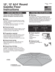
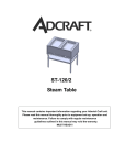
Audio/Video Stand Warranty
One (1) Year Limited Warranty
THIS PRODUCT IS DESIGNED AND INTENDED ONLY FOR USE WITH THE SPECIFIED HP MODEL
TELEVISION ONLY. USE WITH TELEVISIONS OTHER THAN THE SPECIFIED HP MODEL WILL VOID
THIS WARRANTY.
This product is warranted, with the exception of glass, to the original purchaser at the time of purchase
and for a period of one (1) year thereafter. Glass is warranted to the original purchaser at the time of
purchase and for a period of thirty (30) days thereafter. Warranty is only valid in the United States of
America.
In order to provide you with timely assistance, please thoroughly inspect your furniture for missing or
defective parts immediately after opening the carton. To receive replacement or missing part(s) under
this warranty, go to our website at www.hp.com or call our Customer Service Department at (888) 7792858. Please have the model number of the stand and part number(s) for reference. You will also need
your sales receipt or other proof of purchase. Replacement part(s) will be shipped to you at no charge
with HP assuming all shipping and handling expense.
We warrant to you, the original purchaser, that our furniture and all of its parts and components are free
of defects in material or workmanship. "Defects", as used in this warranty, is defined as any
imperfections that impair the use of the furniture or product.
Our warranty is expressly limited to the replacement of furniture parts and components. For one (1) year
after the date of purchase, HP will replace any part described on the enclosed furniture parts list that is
defective in material or workmanship.
This warranty applies under conditions of normal use. Our furniture products are not intended for outdoor
use. The warranty does not cover: 1) defects caused by improper assembly or disassembly; 2) defects
caused by shipping, claims for damage during transit to you should be placed immediately by you to the
transportation company; 3) defects occurring after purchase due to product modification, intentional
damage, accident, misuse, abuse, negligence or exposure to the elements; 4) cosmetic damage and
5) labor or assembly costs.
There are no warranties, express or implied, including without limitation merchantability or fitness for
particular use, except as (i) contained herein or (ii) required by applicable law in the state whose law
governs (which shall be New Jersey absent controlling law imposing the law of another state in lieu
thereof as governing law). All warranties of whatsoever derivation shall be limited to the term set forth
above, unless otherwise required by applicable law.
Manufacturer’s employees or representatives’ … ORAL OR OTHER WRITTEN STATEMENTS DO NOT
CONSTITUTE WARRANTIES, shall not be relied upon by Buyer, and are not a part of the contract for
sale or this limited warranty.
Except as provided herein, HP shall have no liability or responsibility to the purchaser or any other
person or entity with respect to any liability, loss or damage caused directly or indirectly by use of the
product, including, but not limited to, any incidental or consequential damages. Some states do not
allow limitation on how long an implied warranty can last or the exclusion of limitation of incidental or
consequential damages, so the above limitation and exclusion may not apply to you.
This warranty gives you specific legal rights. You may also have other rights, which vary from state to
state.
www.hp.com
Assembly Instructions
For Model TS5220 Silver Audio Video Stand
FOR USE WITH HP MODEL IDB5220N TELEVISION
PART #
REQUIRED
TOOLS
Parts List
PART DESCRIPTION
Allen Wrench
QUANTITY
Philips Screwdriver
Assembly Instructions
NOTE: TWO PEOPLE ARE RECOMMENDED TO ASSEMBLE THIS TABLE.
Fig. 1
1. Side Assembly
6
A. INSERT two Cam Locks (8) into each of the Side Support
Panels (6). INSERT five Cam Lock Connector Bolts (9) into
the Left Front Panel (4) and Right Front Panel (5).
9
9
34mm Cam Lock Connector Bolt
10
10
50mm Screw
16
12
30mm Screw
4
8
Cam Lock
11
Glass Shelf Support Pin
4
A. PLACE the Bottom Shelf (1) on a soft flat surface with the pre-assembled feet
facing up. INSERT four Cam Locks (8) into the large holes. Make sure the thread openings of the
Cam Locks face toward the outside edge of the Bottom Shelf (1).
13
Plastic Screw Caps
8
Left & Right Front Panels
2
B. CAREFULLY TIP the Bottom Shelf (1) on the front (longer) edge so that the underside is facing
away from you. ALIGN the edges of the Side Panels (6) and Bottom Shelf and INSERT the Cam
Lock Connector Bolts (9) into the Cam Locks (8). SECURE the Side Panels (6) to the Bottom Shelf
by tightening the Cam Locks with the philips screwdriver, DO NOT OVERTIGHTEN. INSERT two
50mm Screws (10) through the predrilled holes in the Bottom Shelf and
into the Side Panels (6) and tighten.
4 (Left)
5 (Right)
6
3
10
Side Support Panels
Rear Support Panel
with Cable Management
2
1
2
Top Shelf
1
7
Glass Shelf
1
1
Bottom Shelf
1
FOR YOUR SAFETY, PLEASE FOLLOW THESE PRECAUTIONS:
! ALWAYS REMOVE THE TV AND OTHER EQUIPMENT FROM THE FURNITURE PRIOR TO MOVING THE ASSEMBLED UNIT.
! BE CAREFUL WHEN MOVING THE ASSEMBLED FURNITURE AFTER THE GLASS SHELF HAS BEEN INSTALLED,
AND/OR WHEN THERE IS EQUIPMENT LOCATED ON THE FURNITURE AS THIS MAY CAUSE THE SHELF TO BECOME
UNSECURED AND FALL.
! WHEN IN USE, THIS FURNITURE MUST BE PLACED ON A FLAT, SOLID AND LEVEL SURFACE.
! DO NOT LEAN ON THE TV WHEN IT IS ON THE TV STAND.
! DO NOT CLIMB OR STEP ON THE STAND.
! DO NOT BANG OR PLACE YOUR OWN WEIGHT ON THE GLASS SHELF.
! DO NOT PLACE ITEMS ON THE SHELVES WHICH EXCEED THE MAXIMUM WEIGHT LIMITS OF 200 LBS. FOR TOP SHELF
AND 50 LBS. FOR GLASS SHELF
8
11
B. INSERT a Glass Shelf Support Pin (11) into the center hole
of each Side Support Panel (6).
4,5
C. ATTACH each Front Panel (4 & 5) to each Side Support
Panel (6) as shown in Fig. 1. TIGHTEN Cam Locks (8) with
Philips Screwdriver, DO NOT OVERTIGHTEN.
2. Table Assembly
10
C. CAREFULLY TIP the unit upside down and SECURE the
Rear Support Panel (3) to the table bottom using four Screws
(10).
13
D. CAREFULLY TIP the partially assembled table over so that
it is sitting upright on the floor. PLACE two Shelf Support
Pins (11) into the holes in the rear panel as shown in
Fig. 2. Make sure the rubber pads are facing up.
2
6
E. PLACE the Glass Shelf (7) into the partially
assembled table and onto the four Shelf
Support Pins (11) as shown in Fig. 2.
F. PLACE the Top Shelf (2) onto partially
assembled table. INSERT the Cam Lock
Connector Bolts (9) in the Front Panels
(4,5) into the Cam Locks (8) in the Top
Shelf and turn Cam Locks to tighten. DO
NOT OVERTIGHTEN. SECURE Top Shelf
using eight 50mm Screws (10).
Fig. 2
3
8
11
G. INSERT eight Plastic Screw Caps (13)
over the Screws (10) which were inserted
into the Top Shelf (2), as shown in Fig. 2.
FOR YOUR SAFETY, SECURE THE TV TO
THE TABLE FROM BENEATH THE THE TOP SHELF
USING 4 OF THE SUPPLIED 30MM BOLTS (PART #12)
8
7
4
9
1
5
10
8
NOTE: THE MIDDLE GLASS SHELF (7) CAN NOT BE REMOVED
ONCE THE TOP SHELF (2) IS SECURED, BUT IT CAN SHIFT OR TIP
FORWARD WHEN THE TABLE IS MOVED OR IF THE SHELF SUPPORT PINS (11)
ARE NOT PLACED SECURELY IN THEIR HOLES WITH THE RUBBER PADS FACING
UPWARDS. ALWAYS PLACE HEAVIEST COMPONENTS ON LOWER SHELF.
10
8
6