1
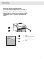
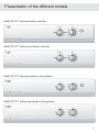
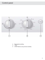
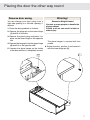
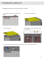
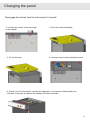
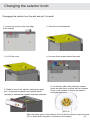
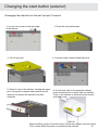
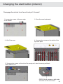
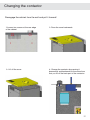
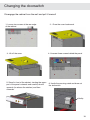
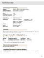
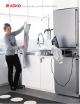
SERVICE MANUAL DRYING CABINET Contents Servicing………………………………………………………... Presentation of the different models……………………………. Setting the temperature selector knob…………………………... Control panel……………………………………………………. Placing the door the other way round…………………………... Changing the casing unit………………………………………... Changing the panel……………………………………………… Changing the selector knob……………………………………... Changing the fan/motor and the protection against overheating.. Changing the element…………………………………………… Changing the thermostat………………………………………... Changing the timer……………………………………………… Changing the start button (exterior)…………………………….. Changing the start button (interior)…………………………….. Changing the contactor…………………………………………. Changing the door contact breaker……………………………... Changing the hangers…………………………………………… Technical information 120V……………………………………. Circuit diagram DC7171 with start button, 120V………………. Trouble shooting........................................................................... 3 4 5 6 7 8 9 10 11 12 13 14 15 16 17 18 19 20 21 22 Servicing Before you contact customer service, you should find out the designation of the model, its type and its serial number. The designation of the model is inscribed on the cabinet control panel. The type and the serial number are inscribed on the identification plate which is placed on the inside of the cabinet. 1 X DC XXX 2 3 ???????????????? ????????????????????? ???????????????? 4 5 1. Model 2. Identification plate (inside) 3. Article number 4. Serial number (12 figures) 5. Type Typskylt 3 Presentation of the different models ASKO DC7171 with start button, with text ASKO DC7171 without start button, with text ASKO DC7171 with start buttons, with symbols ASKO DC7171 without start button, with symbols 4 Setting the temperature selector knob Do not use heat when drying foam-rubber lined clothing or similar articles The cycle control regulates the temperature on a stepless scale, from no heat to the normal position with full temperature. Setting Articles to be dried Temperature 1 Air fluff Foam-rubber products, plastics, heat-sensitive items Fan only 2 Low Sports clothing, underwear, shirts, blouses, silk goods, machinewashable knit products Low 3 Normal Heavy work clothing, denim, cotton garments, cotton sweatshirts Normal 5 Control panel 1. 2. 3. Temperature setting Timer START-button (only certain markets) 6 Placing the door the other way round Reverse door swing Warning! You can change your door swing from a right-side opening to a left-side opening, if desired. 1. Place the drying cabinet on its back. 2. Remove the hinge pin at the lower hinge (1) and lift off the door. 3. Remove the plastic plug and press it in place on the lower hinge on the opposite site. 4. Remove the hinge pin from the upper hinge (2) and fit it to the opposite side. 5. Unscrew the glove hanger on the inside of the door and turn it completely around. 2 Excessive Weight Hazard Use two or more people to handle the drying cabinet. Failure to do so can result in back or other injury. The glove hanger is secured with four screws. 6. Rotate the door, position it and secure it with the lower hinge pin (1). 1 7 Changing the casing unit Disengage the cabinet from the wall and pull it forward! 1- Loosen two screws at the rear edge of the cabinet 3- Lift off the cover 2- Draw the cover backwards 4- Unscrew four screws on the inside of the top cover plate 5- Unscrew two screws on the side of the casing unit, draw it backwards and lift it off. 8 Changing the panel Disengage the cabinet from the wall and pull it forward! 1- Loosen two screws at the rear edge of the cabinet 3- Lift off the cover 2- Draw the cover backwards 4- Unscrew three screws behind the panel 5- Stand in front of the cabinet, slanting the upper part of the panel outwards and carefully draw it upwards (to release the catches) and then outwards. 9 Changing the selector knob Disengage the cabinet from the wall and pull it forward! 1- Loosen two screws at the rear edge of the cabinet 3- Lift off the cover 2- Draw the cover backwards 4- Unscrew three screws behind the panel 5- Stand in front of the cabinet, slanting the upper part of the panel outwards and carefully draw it upwards (to release the catches) and then outwards. 6. On the back side of the panel the selector knobs are held firmly in place with two catches. Press in the catches to release the selector knob and draw it out. PRESS IN When installing, press in the selector knob so that the catches snap into place. (This is done when the panel is mounted on the cabinet) 10 Changing the fan/motor and the protection against overheating Disengage the cabinet from the wall and pull it forward! 1- Loosen two screws at the rear edge of the cabinet 3- Lift off the cover 2- Draw the cover backwards 4- It is firmly fixed with 4 screws Changing the protection against overheating Fixed on the element, screwed firmly into place with 2 screws 11 Changing the element Disengage the cabinet from the wall and pull it forward! 1- Loosen two screws at the rear edge of the cabinet 3- Lift off the cover 2-Draw the cover backwards 4- Unscrew four screws on the inside of the top cover plate 5- Unscrew two screws on the side of the casing unit, draw the casing unit backwards and lift it off. 6. On the underside of the casing unit you will find 4 screws which hold the element firmly in place. 12 Changing the thermostat Disengage the cabinet from the wall and pull it forward! 1- Loosen two screws at the rear edge of the cabinet 3- Lift off the cover 5- Unscrew two screws on the side of the casing unit, draw the casing unit backwards and lift it off. Screws for the thermostat 2- Draw the cover backwards 4- Unscrew four screws on the inside of the top cover plate 6. Remove the 2 screws from the front, take the bulb out of the bulb socket 13 Changing the timer Disengage the cabinet from the wall and pull it forward! 1- Loosen two screws at the rear of the cabinet 3- Lift off the cover 5- Unscrew two screws on the side of the casing unit, draw the casing unit backwards and lift it off. 2- Draw the cover backwards 4- Unscrew four screws on the inside of the top cover plate 6. TRemove the 2 screws which hold the timer in place on the front side of the casing unit. Screws 14 Changing the start button (exterior) Disengage the cabinet from the wall and pull it forward! 1- Loosen two screws at the rear edge of the cabinet 2- Draw the cover backwards 4- Unscrew three screws behind the panel 3- Lift off the cover 5- Stand in front of the cabinet, slanting the upper part of the panel outwards and carefully draw it upwards (to release the catches) and then outwards. 6. On the back side of the panel the selector knobs are held firmly in place with two catches. Press in the catches to release the start button and draw it out. PRESS IN When installing, press in the start button so that the catches snap into place. 15 (This is done when the panel is mounted on the cabinet) Changing the start button (interior) Disengage the cabinet from the wall and pull it forward! 1- Loosen two screws at the rear edge of the cabinet 3- Lift off the cover 2- Draw the cover backwards 4- Unscrew four screws on the inside of the top cover plate 5- Unscrew two screws on the side of the casing unit, draw the casing unit backwards and lift it off. PRESS IN the catches on both sides and draw out the start button. 16 Changing the contactor Disengage the cabinet from the wall and pull it forward! 1-Loosen two screws at the rear edge of the cabinet 3- Lift off the cover 2- Draw the cover backwards 4- Change the contactor by pressing it downwards and backwards at the same time that you lift off the back part of the contactor. 17 Changing the doorswitch Disengage the cabinet from the wall and pull it forward! 1- Loosen two screws at the rear edge of the cabinet 3- Lift off the cover 5- Stand in front of the cabinet, slanting the upper part of the panel outwards and carefully draw it upwards (to release the catches) and then outwards. 2- - Draw the cover backwards 4- Unscrew three screws behind the panel 6. Unclip the securing catch and draw out the doorswitch Unclip 18 Changing the hangers Detach the hanger stop on both sides and pull out the hangers. HANGER STOP Changing the door edging strip Turn up the edging strip, unscrew the screws from the metal panel and change the edging strip. 19 Technical data Technical characteristics Capacity: About 7 1/2 lbs (3.5 kg) of laundry (cotton) Dewatering capacity: 0.56 ounce/min (16 gram/min) Electrical connection: Single-phase, 120 V, 60 Hz Motor: 43 W Heating element output: 1200 W Overheating protection: Yes Time switch: Adjustable up to 4 hours Hanging length: 630 in. (16 meters) Dimensions: Height 68” (173.0 cm) Width Depth 23 7/16” (59.5 cm) 24” (61.0 cm) Weight: About 133 lbs (60 kg) Color: White or Titanium Noise level: Max. 58 dB(A) Adjustable 67 3/4” - 68 3/4” (172.0 cm - 174.5 cm) Exhaust When the drying cabinet is working, 45 m³ of moist air are evacuated per hour. This air is taken from the room where the unit is installed. Energy consumption and drying times Drying spun-dried wash *) Setting Energy consumption Drying time Heat Low 0.33 kWh/lb (0.72 kWh/kg) laundry About 210 min. 45°C (113°F) Normal 0.34 kWh/lb (0.75 kWh/kg )laundry About 130 min. 65°C (149°F) *) The values can vary depending on spin dry speeds. Manufacturing standards See the cabinet’s rating plate Installation spacing for custom cabinetry For built-in installation, minimum ventilation openings in the top and between the cabinet and the rear wall must be ½” (13 mm). 20 Circuit diagram, DC7171, with start button, 120V L1 N 120V Ground / Terre A B Timer / Minuterie Timer Motor Minuterie Moteur b1 b1 Push-To-Start Switch Interrupteur Door Switch Interrupteru de porte Appuyer pour démarrer a1 5 3 1 13 14 A2 Relay Coil R1 Relais bobine R1 Relay Relais 6T 4T High Limit Thermostat A1 2T Thermostate limite haute Fan motor Moteur de ventilateur 600W Operating Thermostat Thermostat de service Heater Element Élément chauffant The elemens is not connected to ground 600W Cat élément n´est pas relié á la terre 21 Troubleshooting Before calling for help, first try to correct the problem using the following guide: Problem Garments are not being dried as expected. The drying cabinet does not produce enough heat even thought the cycle control is activated. Cause Corrective action The house breaker for drying cabinet has tripped. Check. Cycle control and/or time switch has not been correctly set. Check the setting. The drying cabinet is being used in a room with a temperature lower than 0°C (32°F). Normal operation requires installation in a room with a temperature over 0°C (32°F). Poorly spun-dried items or too much remaining moisture in the garments. If the clothing is too wet, use a higher spin speed on the washing machine. Has the items been hung correctly? See the section “Loading”. Have the time and temperature knobs been for too little time or a temperature too low? Increase the program length and temperature to achieve the desired level of dryness. Is the vent pipe/hose too long? Length should not exceed 39 inches (1 m). Is the power plug inserted? Check. Is the drying cabinet door closed? Was the “START” button fully depressed? Press the button again. Has the time switch been set? Check. The overheating protector has tripped. Turn the time switch back to “0” and wait 30 minutes. After 30 minutes has passed, turn the time switch to 30 minutes and press the “Start” button. The overheating protector is faulty. Change the overheating protector Push firmly on the door to make sure it is closed. 22 Article nr. 101863-1 Rev. 1 We reserve the right to make alterations. Printed on environment friendly paper, complying with the requirements of Miljöförbundet (Swedish Environmental Organization) and Naturskyddsföreningens (Swedish Association for nature conservancy).