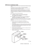
1
Advisor Guide Pedestrian Signal (AGPS) Installation Guide 906-0003 Revision E ● October 13, 2014 Campbell Company AAPS Installation Guide Campbell Company 450 W. McGregor Drive Boise, Idaho 83705 USA Tel: +1-208-345-7459 Fax: + 1-208-345-7481 Last edited: 13 October 2014 This document is copyright © 13 October 2014 by Dick Campbell Company. All rights reserved. No part of this publication may be reproduced, transmitted, transcribed, stored in a retrieval system, or translated into any language, in any form or by any means, electronic, mechanical, photocopying, recording, or otherwise, without prior written permission from Campbell Company. All copyright, confidential information, patents, design rights and all other intellectual property rights of whatsoever nature contained herein are and shall remain the sole and exclusive property of Campbell Company. The information furnished herein is believed to be accurate and reliable. However, no responsibility is assumed by Campbell Company for its use, or for any infringements of patents or other rights of third parties resulting from its use. The Dick Campbell Company name and Campbell Company logo are trademarks or registered trademarks of Campbell Company. All other trademarks are the property of their respective owners Page 2 of 10 906-0003 AGPS Installation Guide Rev E.docx © Dick Campbell Company 2014. All rights reserved Campbell Company AGPS Installation Guide AGPS Installation Guide 906-0003 Document Revision History Revision Revised By Date A Tony Brennan 06-18-2012 B Tony Brennan 10-01-2012 C Phil Tate 10-17-2012 C1 Zane Sapp 12-21-2012 C2 Tony Brennan 12-02-2013 D Tony Brennan 01-20-2014 E Zane Sapp 09-19-2014 906-0003 AGPS Installation Guide Rev E.docx © Dick Campbell Company 2014. All rights reserved Page 3 of 10 Campbell Company AAPS Installation Guide Table of Contents 1 1 Table of Contents ................................................................................................... 4 2 Introduction............................................................................................................. 5 2.1 PURPOSE OF THIS DOCUMENT ....................................................................................................... 5 2.2 ADDITIONAL INFORMATION ............................................................................................................ 5 2.3 CONTACT INFORMATION ............................................................................................................... 5 3 Installation .............................................................................................................. 6 3.1 STANDARD COMPONENTS ............................................................................................................. 6 3.2 INSTALLATION .............................................................................................................................. 6 4 Post Installation ...................................................................................................... 9 4.1 5 OPERATIONAL CHECK .................................................................................................................. 9 Appendix A: Acronyms, Abbreviations & Definitions ............................................ 10 Page 4 of 10 906-0003 AGPS Installation Guide Rev E.docx © Dick Campbell Company 2014. All rights reserved Campbell Company AGPS Installation Guide 2 Introduction 2.1 Purpose of this document This guide covers the installation of the Advisor Guide Pedestrian System (AGPS). It does not cover the configuration of the AGPS. For details on configuring the AGPS, please see the User’s Manual. 2.2 • • • • 2.3 Additional Information For operational information, see the AGPS User’s Manual Reference the Intersection Worksheet for location specific information. See the Installation Quick Guide for a brief graphical installation guide. See the Base Station Mounting Template for an easy to use hole pattern for mounting AGPS base stations. Contact Information The first line of contact should be the distributor that the system was purchased from. If you are unable to contact the distributor, contact Campbell Company directly. 906-0003 AGPS Installation Guide Rev E.docx © Dick Campbell Company 2014. All rights reserved Page 5 of 10 Campbell Company AAPS Installation Guide 3 Installation 3.1 Standard Components 1ea AGPS Base Station o 2ea 1/4-20 x 1 1/2” FHP Screws 1ea Terminal Plate + Nipple o 3ea 6-32 x 1/4” FHP Screws 1ea Signal Power Interface 1ea USB (type B) cable per installation 1ea 5x7 Adapter Plate and sign o 2ea. 8-32 x 1 3/4” FHP Screws 2ea. 8-32 x 1 3/4” PHP Screws o 2ea. 8-32 x 1/4" PHP Screws Or 1ea 9x12 or 9x15 Adapter Plate and sign o 4ea. 8-32 x 1 3/4” FHP Screws o 4ea. 8-32 x 1/4” PHP Screws 400(A) Mounting Hardware o 2ea. 1/4-20 x 1” FHP Screws o 3.2 Installation It is recommended to use an anti-seize compound on all screws going into the pedestrian station. Failure to do so may result in damage to the station if removal is necessary. 3.2.1 Tactile Arrow Orientation Mount the Base Station so the tactile arrow is pointing directly to the crossing destination. THE PEDESTRIAN RELIES ON THIE INFORMATION TO CROSS SAFELY. Some installations do not call out arrow directions and require installation in the field. The tactile arrow is field selectable (left or right) requiring two security screws and a security driver. Campbell Company provides this hardware packet only when specified at the time of purchase. Rubber bumpers on the back plate of the Base Station are adjustable allowing for a number of configurations to ensure a precise fit, especially on decorative or small diameter poles where the station needs to be angled to provide accurate directionality of the arrow. 3.2.2 Base Station Installation Drill and Tap Pole 1. Refer to the Base Station Mounting Template for hole specifications. 2. Mark the point where the PPB will be centered 36” to 42” from the ground. 3. Drill a 1 1/8” through hole 1 1/4” above PPB center. Page 6 of 10 906-0003 AGPS Installation Guide Rev E.docx © Dick Campbell Company 2014. All rights reserved Campbell Company AGPS Installation Guide 4. Drill and tap for a 1/4-20 screw 2 1/4” above PPB center. 5. Drill and tap for a 1/4-20 screw 10 1/2” above PPB center. Mount the Pedestrian Station 1. Route the four conductor cable from the 1 1/8” hole through the pole into the pedestrian signal head for connection to the SPI. 2. Route the four conductor cable and the pedestrian input circuit wires through the terminal plate with nipple installed. 3. Connect the four wires to the terminal block in the back of the station to the connections shown in Figure 1. 4. If there are pedestrian field wires present at the station, route them through the terminal plate and nipple Figure 1. AGPS Wiring and then connect them to the terminal block in the positions shown in Figure 1. 5. Secure protective terminal plate with screws. 6. Attach the pedestrian station to the pole using two ¼ - 20 FHP screws. Adjust rubber bumpers as necessary to ensure a secure fit. 7. Attach the adapter plate and/or sign using provided hardware. The adapter plate and mounting hardware differ depending on size. 3.2.3 400(A) Station Installation 1. Route the four conductor cable from the pedestrian signal head though the hole in the station housing. 2. Connect the four conductor cable to the terminal block on the back of the station to the positons shown in Figure 2. 3. If there are pedestrian field wires present at the station, connect them to the positions shown in Figure 2. 4. Insert the pushbutton into the 400 style housing and secure using two 1/4-20 screws. 906-0003 AGPS Installation Guide Rev E.docx © Dick Campbell Company 2014. All rights reserved Figure 2. AGPS 400(A) Wiring Page 7 of 10 Campbell Company AAPS Installation Guide 3.2.4 Signal Power Interface Installation Do not set the SPI on the bottom of the Pedestrian Signal Head. Failure to attach the SPI vertically on the back surface wall can expose the power supply to water damage and will void the warranty of the SPI. Warning! All SPI leads become hot when at least one of the wires is connected. Disconnect the power to the Pedestrian Signal Head prior to SPI installation 1. Disconnect the power going to the Pedestrian Signal Head prior to installing the SPI. 2. Open the Pedestrian Signal Head Display and locate a ¼-20 tapped hole on the back wall close to the 120VAC three position barrier strip as shown in Figure 3. 3. Mount the SPI horizontally using a 1/4-20 1” FHP. It is important that the wires coming out of each side of the SPI sag below the SPI to prevent water from running down the wires, into the SPI. Figure 3 shows the drip loop in the120 VAC lines and its location to the barrier terminal inside the Pedestrian Signal Head. 4. Attach the four wires from the Base Station to the to the four position terminal block on the SPI following the connections shown in Figure 4. 5. Connect the three 16 AWG wires from the SPI to the three position terminal block for the pedestrian Figure 3. SPI Installed signal display. Figure 4. SPI Wiring 6. Restore power to the signal head and verify that the station operates. Page 8 of 10 906-0003 AGPS Installation Guide Rev E.docx © Dick Campbell Company 2014. All rights reserved Campbell Company AGPS Installation Guide 4 Post Installation 4.1 Operational Check 1. Make sure the station is securely attached to the pole with the arrow pointing to the crosswalk. 2. Verify that the SPI is mounted horizontally in the signal head with the wiring sagging below. 3. When first powered up, an audible locator tone will be present at the station. The locator tone should be audible 6-12 feet from the station. 4. Depress the push button and verify that the pilot light turns on with an acknowledgement message. If pedestrian field wires are connected to the station, verify that pedestrian call is transmitted to the traffic controller. 5. Following a momentary press, verify the Walk message present and the vibro-tactile surface vibrates when the walk sign is on. 6. Repeat again with an extended press. This time the location message should sound and walk message should sound when the walk sign is on. 7. After the Walk message, verify that an audible locator tone is present during the clearance (Flashing Don’t Walk). 8. Recheck all units for a full cycle to ensure all options and features operate as desired. 906-0003 AGPS Installation Guide Rev E.docx © Dick Campbell Company 2014. All rights reserved Page 9 of 10 Campbell Company AAPS Installation Guide 5 Appendix A: Acronyms, Abbreviations & Definitions Term Meaning Adapter Plate (AP) An aluminum plate that mounts to the base station to display crosswalk signs. Base Station (BS) Fully integrated APS station that contains the microcontroller, push button, speaker, adapter plate Extended Press On APS, holding the pedestrian push button down may activate special features, including audible beaconing and extended pedestrian clearance interval. Intersection Worksheet Intersection Map of street names and station locations provided with installation packet. Signal Power Interface (SPI) Power Source that interfaces with Pedestrian Signal Head power for Base Station Interface. Station ID Identification number of station for location and custom messaging Page 10 of 10 906-0003 AGPS Installation Guide Rev E.docx © Dick Campbell Company 2014. All rights reserved