1
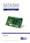
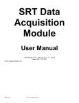
Campbell Company Advisor Advanced Pedestrian System User’s Manual AAPS User’s Manual 906-0005 Version C ● May 9, 2014 906-0005 AAPS Users Manual Rev C Campbell Company 450 W. McGregor Drive Boise, Idaho 83702 USA Tel: +1-208-345-7459 Fax: + 1-208-345-7481 Last edited: 09 May 2014 This document is copyright © 09 May 2014 by Dick Campbell Company. All rights reserved. No part of this publication may be reproduced, transmitted, transcribed, stored in a retrieval system, or translated into any language, in any form or by any means, electronic, mechanical, photocopying, recording, or otherwise, without prior written permission from Campbell Company. All copyright, confidential information, patents, design rights and all other intellectual property rights of whatsoever nature contained herein are and shall remain the sole and exclusive property of Campbell Company. The information furnished herein is believed to be accurate and reliable. However, no responsibility is assumed by Campbell Company for its use, or for any infringements of patents or other rights of third parties resulting from its use. The Dick Campbell Company name and Campbell Company logo are trademarks or registered trademarks of Campbell Company. All other trademarks are the property of their respective owners Page 2 of 28 Document Name: 906-0005 AAPS Users Manual Rev C © Campbell Company 2014. All rights reserved. Campbell Company AAPS User’s Manual AAPS User’s Manual Version: [C] Revision Date [May, 10 2014] Revision History User Manual Rev Software Version APC # Software Version APB Revised By Date A 1.0 1.5.1 Tbrennan 7-19-12 B 2.3.0 2.3.0 zsapp 11-1-12 C 3.1.3 2.3.0 zsapp 5-10-14 Document Name: 906-0005 AAPS User’s Manual © Campbell Company 2014. All rights reserved. Page 3 of 28 906-0005 AAPS Users Manual Rev C Table of Contents 1 Introduction............................................................................................................. 5 1.1 SYSTEM ORGANIZATION ............................................................................................................... 5 1.2 W EB BROWSER ........................................................................................................................... 5 2 Overview ................................................................................................................ 6 3 Features ................................................................................................................. 7 3.1 KEY FEATURES............................................................................................................................ 7 3.2 CUSTOM MESSAGE AND SOUND OPTIONS ...................................................................................... 7 3.3 COMPONENTS ............................................................................................................................. 8 3.4 SAFETY ...................................................................................................................................... 9 4 System Components ............................................................................................ 10 4.1 AAPS COMPONENT DESCRIPTION ............................................................................................... 10 4.2 SYSTEM SPECIFICATION REQUIREMENTS...................................................................................... 10 5 Installation ............................................................................................................ 11 5.1 INSTALLING THE SYSTEM ............................................................................................................. 11 5.2 SYSTEM OPERATIONAL CHECK FOLLOWING INSTALLATION ............................................................. 12 6 System Configuration ........................................................................................... 13 6.1 ACCESSING THE W EBPAGE ......................................................................................................... 13 6.2 MAIN SCREEN ........................................................................................................................... 13 6.3 MAKING CHANGES ..................................................................................................................... 14 7 Troubleshooting.................................................................................................... 23 7.1 APC TROUBLESHOOTING ........................................................................................................... 23 7.2 RUNNING A PATCH ..................................................................................................................... 24 7.3 APB TROUBLESHOOTING............................................................................................................ 25 8 Appendix A: Acronyms, Abbreviations & Definitions ............................................ 27 9 Appendix B: Related Documentation.................................................................... 28 9.1 OBTAINING DOCUMENTATION ...................................................................................................... 28 Page 4 of 28 Document Name: 906-0005 AAPS Users Manual Rev C © Campbell Company 2014. All rights reserved. Campbell Company AAPS User’s Manual 1 Introduction 1.1 System Organization The Advisor Advanced Pedestrian System (AAPS) is a network based control system that provides flexibility and capacity without requiring additional infrastructure. The AAPS has three major components: the Advanced Pedestrian Controller (APC) that provides an interface in the traffic controller cabinet, the Advanced Pedestrian Button (APB) is at each corner, and communicates with the APC. A web based interface is accessed via Ethernet allowing traffic agency technicians to view system operations and control operating characteristics. The Advisor Advanced Accessible Pedestrian (AAPS) is identified with an ID#, Version#, and release# 1.2 Web Browser A readily available web browser (Google Chrome, Firefox or IE) and an IP address will establish communication with the APC. The web based application is password protected and records all modifications and pedestrian activity for the previous month. Document Name: 906-0005 AAPS User’s Manual © Campbell Company 2014. All rights reserved. Page 5 of 28 906-0005 AAPS Users Manual Rev C 2 Overview The Advisor Advanced Pedestrian System utilizes web based management to update and monitor the system remotely over network communication via desk top computer, laptops, or any device that is web browser compatible. Operators can view the AAPS status in real time and control audio and visual components with the capability to upload files directly into individual pedestrian stations or download reports generated by the APC. The Advanced Pedestrian Controller (APC) uses Ethernet over Power (EoP) communications on existing low power pedestrian field wiring. A locator tone, controlled with ambient gain compensation, tells a pedestrian that the crossing is equipped with APS and where it can be found. An extended press provides specific intersection information and access to additional functions. The audible walk tone or message is accompanied by a vibro-tactile indication during the visual walk display. Optional clearance phase indications may provide additional information to the pedestrian where appropriate Each Advisor Advanced Pedestrian System is configured at the factory, but customization and set-up are simply updated through a web browser making it extremely easy to customize the needs of complex intersections Campbell Company cannot guarantee a 2 wire system will work properly in all instances, especially if a single common to the buttons and signal lighting is shared. Each case will have to be tried and proven because it depends on the condition of the wires, splices, etc… In the event there are no field wires, AAPS can be swapped out for a AGPS unit as long as there is no damage to the AAPS units. Please carefully read the contents of this manual in its entirety so you fully understand the many functions and options the system provides. Page 6 of 28 Document Name: 906-0005 AAPS Users Manual Rev C © Campbell Company 2014. All rights reserved. Campbell Company AAPS User’s Manual 3 Features 3.1 Key Features Standard Features Two Conductor Advantage • Uses existing field wiring from traffic control cabinet. No additional wires required • Significantly reduces installation cost with no excavation costs System Features • Independent time of day/night mode volume settings for locator tone and audio outputs • Independent non-locator AGC and locator AGC settings • Maximum volume dynamic range 0 – 100dB • Audio output options o Default, Identify, Off and EPAPS 3.2 • Beaconing or group walk • Button rated at 100 x 10⁶ actuations • Webpage configuration and audio upload • Report download capability in .csv format • Ethernet Access • Remote Communication • Ped Count/Call Data • Messages can be recorded in any language(s) and uploaded • Emergency pre-emption Custom Message and Sound Options Locator Tone – Plays an audible sound at one second intervals to let pedestrian know that the push button is equipped with APS Acknowledgement Message – Plays “wait” message when momentary press is detected Document Name: 906-0005 AAPS User’s Manual © Campbell Company 2014. All rights reserved. Page 7 of 28 906-0005 AAPS Users Manual Rev C Location Message – Provides the name of the street being crossed at a cross street and other vital information. Several languages can be recorded and available for use. Walk Message – Provides the name of the street the pedestrian is crossing. Clearance Sounds/ Countdown – Plays an audible tone to let pedestrian know of clearance phase. By request, an audible count down of the pedestrian signal head can be provided. Custom Recording Options Custom recording messages can be created in a .wav format independently. Free web base software (Audacity) and recording grade micro-phone in a quiet location can produce professional grade messaging. Contact Campbell Company to learn more about producing custom messages. 3.3 Components Each Advisor Advanced Pedestrian System includes the following: • Base Station(s) - APB o 2ea ¼-20 X 1 ½” FHP Screws • 1ea (5x7) Adapter Plate, Sign, & Hardware o 2ea 8-32 X 1 ¾” FHP Screws o 2ea 8-32 X 1 ¾” PHP Screws o 2ea 8-32 X ¼” PHP Screws APC • Or 1ea (5x9) Sign & Hardware (no Adapter Plate) o 4ea. 8-32 X 1 ¾” PHP Screws • Or 1ea (9x12 or 9x15) Adapter Plate, Sign, & Hardware o 4ea 8-32 X 1 ¾” FHP Screws o 4ea 8-32 X ¼” PHP Screws APC • 1ea APC with power cable • 1ea APC input cable (25 conductor) • 1ea APC output cable (9 conductor) • 1ea 7ft EoP Cable (2 conductor) Page 8 of 28 Document Name: 906-0005 AAPS Users Manual Rev C © Campbell Company 2014. All rights reserved. Campbell Company AAPS User’s Manual • 1ea EoP Termination Board o 2ea ¼-20 x 1” FHP 3.4 Safety The Advance Pedestrian Controller (APC) is protected by a circuit breaker at the front switch and all pedestrian field wiring is fused with resettable fuses. The APC chassis is grounded through an earth ground connection to prevent shock hazard. All general purpose inputs are optically isolated and transient protected against any other equipment interfaced to the APC. The APC is provided with a detachable power cord for quick- disconnect capability. Document Name: 906-0005 AAPS User’s Manual © Campbell Company 2014. All rights reserved. Page 9 of 28 906-0005 AAPS Users Manual Rev C 4 System Components 4.1 AAPS Component Description Advanced Pedestrian Controller (APC) The Advanced Pedestrian Controller (APC) interfaces with the traffic control cabinet. Ethernet over Power (EoP) communications are used on existing low power pedestrian field wiring to relay information to the APB. Advanced Pedestrian Button (APB) The APB is a fully integrated pedestrian station that relays the state of the pedestrian walk signal in audible, vibro-tactile and visual forms. Termination Board Consolidates field wiring to two conductor to attach to the face of the APC. Also provides for fusing of the field wires. Web Page The Web Page interface is accessed via Ethernet allowing traffic agency technicians to view system operations and control operating characteristics. 4.2 System Specification Requirements Power Requirements • APC Input Voltage - 120 VAC • APC Power - 1.68W • APC Current - 270 mA • APB Input Voltage – 12-18 VAC • APB Input current - 140mA • APB Input Power - 2.5 W per station Communication to the APC • Interface – Web Browser • Data Format of logs - .csv • Firmware Update - Ethernet Page 10 of 28 Document Name: 906-0005 AAPS Users Manual Rev C © Campbell Company 2014. All rights reserved. Campbell Company AAPS User’s Manual 5 Installation 5.1 Installing the system The Advance Pedestrian Controller resides in the traffic control cabinet at the intersection. 120V AC is required to power the APC. A DB25 cable connects to the outputs to the pedestrian display from the traffic controller cabinet for the pedestrian phases. A (DB9) cable connects to the pedestrian pushbutton inputs in the traffic controller cabinet (PB2, PB4, PB6, PB8, etc) The APC utilizes Ethernet over Power (EoP) to communicate with the APBs. A termination board consolidates the control cabinet field wiring into a single two conductor wire that makes connection to the APC. The 18 VAC from the field wires provides power to the APB. If the control cabinet is on a secured network, the Ethernet port can be utilized for remote connectivity. A laptop or web based device with an Ethernet connection and cable is required to connect to the APC directly to establish communications and access the operating software. Installation of an AAPS station utilizing a two man crew approximately 45 minutes to 1 hour (assuming no complications) SEE INSTALLATION MANUAL FOR DETAILED FOR DETAILED INSTALLATION INSTRUCTIONS. Document Name: 906-0005 AAPS User’s Manual © Campbell Company 2014. All rights reserved. Page 11 of 28 906-0005 AAPS Users Manual Rev C 5.2 System Operational Check Following Installation 1. Once the power cable to the APC is installed, verify that all other cables are securely connected to the front of the APC. 2. Make sure the power switch is in the OFF position before attaching the 120 VAC cord. 3. Turn the power switch to the On position allowing the APC to power up. The red status light should be blinking when the APC begins communicating with the APBs. (May take up to a minute to establish communications) 4. The Station Numbers will display Up arrow (OK) or Down arrow (ATTN) for each APB on the webpage and on the front panel of the APC. Depress the push button on the APB and verify the red LED turns on with an audible message “Wait”. 5. When the Walk Signal is On, verify the Walk Phase message or percussive tone is present and the vibro-tactile button vibrates concurrently. 6. Repeat again with 2 second extended press and verify the red LED turns on with an audible location message, “Wait to Cross”. 7. After the Walk Phase message, verify an audible locator tone is present at the clearance phase (Flashing Don’t Walk). 8. Recheck all units for a full cycle to ensure all options and features operate as desired. 9. Depending on intersection location, factory default settings for volume, AGC, and vibotactile settings may require modifications. Proceed to the System Configuration section for details. 10. When you are satisfied that all units are working properly, install signs on each Base Station or 400 style station. Page 12 of 28 Document Name: 906-0005 AAPS Users Manual Rev C © Campbell Company 2014. All rights reserved. Campbell Company AAPS User’s Manual 6 System Configuration 6.1 Accessing the Webpage To make changes and view the AAPS webpage simply plug an Ethernet cable into the Ethernet port on the front of the APC. Then connect the Ethernet cable into your laptop. Start up a web browser such as Google Chrome and type in the IP 192.168.1.101 into the address bar. (See Below) Figure 1 Webpage Address bar You will see the following screen pop up looking for credentials. Default user name: admin Password: password. Figure 2 Authentication Page 6.2 Main Screen The first screen is shown below it gives the status of the pedestrian system (figure 5.) To view this screen click “Here” to enable real time status Figure 3 Status Page The Pedestrian Signal Status shows the state of the Signal (DW, FDW, W) and if a call has been placed. Stations Status bar will show a state of the stations; Document Name: 906-0005 AAPS User’s Manual © Campbell Company 2014. All rights reserved. Page 13 of 28 906-0005 AAPS Users Manual Rev C The Status tab gives an overview of the system. The System tab allows for global settings to be adjusted. The Station tab allows for individual station settings to be adjusted. The Sound tab allows for audio files to be changed. The Network tab allows for changes to the APC IP address. The Time tab allows for the time to be adjusted. The Log Files tab is where log files are located. The APC Links tab allows for all APC’s IP addresses to be stored. The Advanced tab is where advanced settings can be found. Log out tab logs you out of the system. 6.3 Making Changes 6.3.1 System Changes System Tab: This tab is where changes are made to the entire system Figure 4 a. The check boxes at the beginning signify what stations are active. To add a station, click the checkbox and it will add more stations to the system (figure 6.) Black means checked, white means unchecked. b. AAPS mode: 4 options; Off, Default, EP APS, and Identify (figure 6.) Page 14 of 28 Document Name: 906-0005 AAPS Users Manual Rev C © Campbell Company 2014. All rights reserved. Campbell Company AAPS User’s Manual c. d. e. f. g. h. i. j. k. l. m. n. 6.3.2 i. Off behaves like a typical button, places calls, no Audio ii. Default is normal APS operation iii. EP APS only actuates APS audio when an extended press is placed iv. Identify will put the APB’s into a mode where their LED’s will blink the assigned station ID (troubleshooting) Extra-press mode: places two calls to the traffic controller one for current cycle and one for following cycle Vib Call Pulse: Allows for vibrotactile feedback when the button is pressed Auto Recall: When checked constant calls will occur if a button is at ATTN Audio Countdown: When checked audible countdown will be enabled Locator AGC: When checked locator AGC will be enabled. If un-checked locator tone will be constant Clearance mode: 5 options Off (no Beaconing), Ping Pong, Dest/Init beaconing and Audible countdown. i. Destination beaconing implements beaconing (only the destination APB will beacon in the clearance phase) ii. Initiation beaconing implements beaconing at the initiation station only. Night mode: Check the box to enable and then set the time for the hours that you would like to adjust the volume differently AGC responsiveness: Adjusts how quickly the ambient gain responds. (1-20, 20 least responsive) Walk message Timeout: Refers to a rest in walk situation, adjusts the time the walk message will timeout without being interrupted by the flashing don’t walk. Extended press time: Adjusts the length time required to place an extended press or APS call. Repeated Acknowledgement: Number of seconds between each repeated acknowledgement message (0 means no repeat) Submit system Configuration button: will submit all changes to APC – must be pressed once all settings are made Note: this only saves settings! To update buttons go to the station tab and click “send all settings” Changing Station Settings The most common changes will have to do with the Station tab Shown Below. Document Name: 906-0005 AAPS User’s Manual © Campbell Company 2014. All rights reserved. Page 15 of 28 906-0005 AAPS Users Manual Rev C Figure 5 Station Tab All active stations will be shown in this tab. To change the Signal (phase) of the button, change the Phase number. To change the group of the button, change the Group number To change the volume level, enter a number between -300 and +300. Defaults are shown above. In order to make the changes permanent click “Save APB Configuration to APC.” To save and send all settings to buttons click “Save and Send All Settings.” Buttons with ID’s can be changed back to “new.” Simple change old station ID to be the ID of the button you want to be “new” leave New station ID at New and click “Change ID”. 6.3.3 Changing Audio files The Sound File tab allows for audio files to be uploaded to individual stations. a. First add sound files to the file system. Click Choose Files/ select them/ then click upload (figure 6.) Page 16 of 28 Document Name: 906-0005 AAPS Users Manual Rev C © Campbell Company 2014. All rights reserved. Campbell Company AAPS User’s Manual b. Next find the message that you will be changing the audio files on. c. Simply click on the dropdown box and select each audio file for each message on each station slot (figure 7). d. Click “Send” in the matrix (figure 6) to send audio files to the ped stations. a. Message that is to be sent is on the left. All messages button is one from the bottom. Figure 6 Audio send Matrix/Audio list Document Name: 906-0005 AAPS User’s Manual © Campbell Company 2014. All rights reserved. Page 17 of 28 906-0005 AAPS Users Manual Rev C Figure 7 Setting up audio files 6.3.4 Changing APC IP In order to remotely communicate with the APC the IP address must be set up. a. Before changing settings consult you IT Department. Also, remember that the IP address is how access is granted to the webpage. If the IP address is changed document it! Figure 8 Network Tab 6.3.5 Setting the Time The Time tab is used for setting up the Real Time clock There are two ways of setting the time: Page 18 of 28 Document Name: 906-0005 AAPS Users Manual Rev C © Campbell Company 2014. All rights reserved. Campbell Company AAPS User’s Manual a. NTP enable or getting the time from the internet. Note: the APC must be able to access to the network and an IP address must be entered in the NTP server box. b. The time can be set by clicking Submit Time configuration or the Day Month and Year can be manually entered. Once the time options are chosen click Submit Time configuration. Figure 9 Time Tab 6.3.6 Viewing Log Files There are three sets of logs to be viewed: APB log, Event log, and System log. Pedcall log reports ped call counts by hour by day Event logging reports any conflicts and/or loss of station communication System logging reports changes made to the system. Figure 10 Log File tab 6.3.7 Configuring the APC Link Tab APC links tab will keep track of all the APC’s on the network on one APC. 1. Make sure the network APC is viewable on the network. 2. Enter a Name or the location of the network APC 3. Type in https:// in the URL box then the IP address of the network APC a. Example: http://192.168.1.101 Document Name: 906-0005 AAPS User’s Manual © Campbell Company 2014. All rights reserved. Page 19 of 28 906-0005 AAPS Users Manual Rev C 4. Click Add 5. Click the new link to make sure it links to the network APC Figure 11 6.3.8 Configuring the Advanced Tab Figure 12 1. Configuration file is able to be uploaded to the APC. Older versions may not work. 2. Reboot button will do a software reboot. Must be done to set time and IP address for the APC. 3. Reset APB log. This will clear the button log files. 4. Additional users can be created Page 20 of 28 Document Name: 906-0005 AAPS Users Manual Rev C © Campbell Company 2014. All rights reserved. Campbell Company AAPS User’s Manual a. Change password: click on edit user: Will reset the password on the AAPS webpage (Remember what you changed it to! Mark it on Intersection Planning Sheet and store in cabinet Doc Sleeve.) 5. The intersection identification can be found here: a. Location Example: Boise ID b. Intersection: Example: 1st at Main c. CC# (order #) 1234 d. PO # e. Intersection image can be selected here and then click “Submit Intersection Identification” to update APC 6. There are three additional logs that can be accessed: Syslog, bootlog, EoP status. 7. APB Memory allows the user to wipe the button memory completely, view files stored on the button and also view firmware. (figure 13) Figure 13 8. Ped Closure Dwell: Time in (ms) the contacts will closed to the traffic controller to signify a normal press was made. 9. APS Closure Dwell: Time in (ms) the contacts will closed to the traffic controller to signify an extended press was made. Document Name: 906-0005 AAPS User’s Manual © Campbell Company 2014. All rights reserved. Page 21 of 28 906-0005 AAPS Users Manual Rev C Any changes to the advanced configuration should be done with the direction of Campbell. 10. CID scan rate: How often the I/O is read. 11. APB update rate: How often the buttons receive an update. 12. Display Update rate: How often the Front panel display is updated. 13. Display timeout: Time before the front panel display times out (shuts off) 14. Wire map: The wire mapping can be changed a. Walk input: Able to choose what phases are assigned to what pins by color code. b. Don’t walk Input: Able to choose what phases are assigned to what pins by color code. c. Call output: Able to choose what Pin/wire will place a call on a certain phase. Page 22 of 28 Document Name: 906-0005 AAPS Users Manual Rev C © Campbell Company 2014. All rights reserved. Campbell Company AAPS User’s Manual 7 Troubleshooting The following chapter discusses troubleshooting the AAPS system in three parts: APC, Running Patches and APB. 7.1 APC Troubleshooting Detailed Instructions 1. Check Status light on front panel of the APC (RED and Green). Both should be blinking, RED at a fast speed signifying communication with the buttons, and Green at a ½ second rate. a. If status light (green) has stopped blinking (solid on/off) Contact Campbell Co. for assistance. Figure 14 LED’s/ Screen b. Status screen showing buttons that are running (up arrows) and buttons that are not communicating (down arrows.) 2. No Communication to APC a. Check computer’s IP address Document Name: 906-0005 AAPS User’s Manual © Campbell Company 2014. All rights reserved. Page 23 of 28 906-0005 AAPS Users Manual Rev C i. Hold Windows key+ R and then type in “cmd” and hit enter 1. A prompt will appear (figure 13) ii. Type ipconfig and hit Enter Figure 15 Showing connection and IP address iii. Look at local area connection iv. Make sure IP has the first same three octets (192.168.1) and the last octet is not the same as the APC’s (101) OR that it is not 255 or 1. b. Type the APC’s address in web browser ie: 192.168.1.101 c. If no connection check for LED on computer’s Ethernet port i. Also can try “pinging” APC ii. Open Command prompt (type cmd in the search bar and hit enter) iii. Type ping 192.168.1.101 then Enter iv. The APC will reply if the computer IP is configured properly 7.2 Running a Patch a. Make sure there is communication with the APC (see above) b. Download patch folder and Extract All (right click and choose the option below) Figure 16 Extracting Patch c. Open patch folder (the unzipped one) and open the ips text document v. Add the IP address of the APC unit in the ips text doc and save Page 24 of 28 Document Name: 906-0005 AAPS Users Manual Rev C © Campbell Company 2014. All rights reserved. Campbell Company AAPS User’s Manual d. Double click on patch (windows batch file) Figure 17 Patch e. Click yes to any warnings f. Once the patch is done it will say “Press any key to continue” 7.3 APB Troubleshooting When troubleshooting button problems, first start by bringing up the APC’s webpage. Refer to the Station tab (figure 7) above. 7.3.1 APB Communication issues a. First check voltage on the APB. Should be 16-18 VAC. i. If Voltage is at ~4 VAC the fuse has tripped. ii. Power cycle and check voltage. If fuse trips again disconnect button and power cycle. Voltage correct? a. Yes Replace button b. NoOhm wiring for shorts b. If APB is not communicating you will see ATTN and a red light next the station number. Start up the station tab on the APC. c. If the station that has lost communication is station 1 then the first step would be to try changing the station number. Set up the Change Station ID to the figure shown below and click change. If the button’s ID is zero it will come back up in 15 seconds. d. If an error “button not found” is displayed go to the System tab and uncheck the station that is not communicating. (Meaning remove the button from the system.) Then click submit changes. e. Wait for approximately 30 seconds Document Name: 906-0005 AAPS User’s Manual © Campbell Company 2014. All rights reserved. Page 25 of 28 906-0005 AAPS Users Manual Rev C f. Ctrl-r will refresh the page. Next go back to the system tab and click the station back into the system. Click Submit System Configuration. 7.3.2 Calls placed on two phases i. If one button press places calls on two phases check the grouping (Station Tab). This usually means a grouped button is on an improper phase. ii. To fix, simply change the grouping to be correct. Figure 18 Station settings iii. Page 26 of 28 Typically all buttons on a phase are grouped together Document Name: 906-0005 AAPS Users Manual Rev C © Campbell Company 2014. All rights reserved. Campbell Company AAPS User’s Manual 8 Appendix A: Acronyms, Abbreviations & Definitions Term Meaning Accessible Pedestrian Signal (APS) A device that communicates information about pedestrian timing in a non-visual format such as audible tones, verbal messages, and/or vibrating surfaces (MUTCD) Actuated operation A type of traffic control signal operation in which some or all signal phases are operated on the basis of actuation (MUTCD) Audible Beaconing Use of sound source to provide directional orientation and alignment information. Automatic Gain Control (AGC) An APS volume control that is automatically responsive to ambient (background) sound. Base Station Fully integrated APS station that contains the Mico-controller, push button, speaker, adapter plate Crosswalk Any portion of a roadway at an intersection or elsewhere distinctly indicated for pedestrian crossing by lines of other marking on the surface (MUTCD) DHCP Dynamic Host Configuration Protocol EoP Ethernet over Powerline Night Mode Ability to change audio volumes by time of day Phase Pedestrian Signal Designation URL Uniform Resource Locator: A specific character string that constitutes a reference to an Internet resource. Document Name: 906-0005 AAPS User’s Manual © Campbell Company 2014. All rights reserved. Page 27 of 28 906-0005 AAPS Users Manual Rev C 9 Appendix B: Related Documentation # Document Title Version Location 1 MUTCD 2009 MUTCD 2009 Edition 2 Americans with Disabilities Act 1996 ADAAG 3 Transportation of Canada 2008 TAC 9.1 Obtaining Documentation The following sections provide sources for obtaining documentation from Campbell Company. 9.1.1 World Wide Web You can access the most current AGPS technical documentation on the World Wide Web at the following site: http://www.pedsafety.com => Support tab. 9.1.2 Product Documentation Technical documentation will be sent electronically on the date your product ships. On-line technical documentation is also available at http://www.pedsafety.com Page 28 of 28 Document Name: 906-0005 AAPS Users Manual Rev C © Campbell Company 2014. All rights reserved.