1
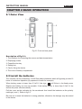
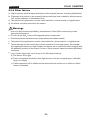
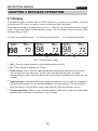
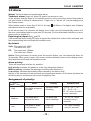
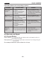
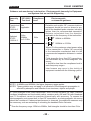
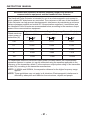
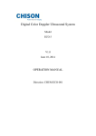
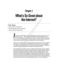
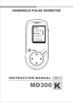
Copyright
Our company owns all rights of this unpublished work and intends to maintain it as a
confidential work. We may also seek to maintain this work as an unpublished copyright. This
publication is to be used solely for the purpose of reference or operation of our software
system. No part of this work can be disseminated for other purposes.
In the event of inadvertent or deliberate publication, we intend to enforce its right to this work
under copyright laws as a published work. Those having access to this work may not copy,
use, or disclose the information in this work unless expressly authorized by our company.
All information contained in this publication is believed to be correct. We shall not be liable for
errors contained herein nor for incidental or consequential damages in connection with the
furnishing, performance, or use of this material. The information this publication refers to is
protected by copyrights or patents and does not convey any license under the patent rights
of our company, nor the rights of others. We do not assume any liability arising out of any
infringements of patents or other rights of third parties.
Content of the manual is subject to change without prior notice.
Version: V1.0I-P
Issue Date: August 12, 2010
CONTENT
CHAPTER 1 Introduction
1.1 Brief Introduction
1.2 Safety Information
1.3 Electromagnetic Compatibility
1.4 Equipment Classification
1.5 Accessories
1.6 Equipment symbol
CHAPTER 2 BASIC OPERATION
2.1 Outer View
2.2 Install the batteries
2.3 Connect the sensor
2.4 SpO2 Monitoring
2.5 Factors that may affect the measurement
CHAPTER 3 DETAILED OPERATION
3.1 Display
3.2 Key Functions
3.3 Mode Introduction
3.4 Data replay and transmission
3.5 Alarm
CHAPTER 4 MAINTENANCE AND REPAIR
4.1 Maintenance
4.2 Troubleshooting
4.3 Warranty and Repair
1
1
1
3
3
3
4
5
5
5
6
6
7
9
9
10
10
11
12
13
13
13
14
APPENDIX A Specifications
17
APPENDIX B The declare of manufacturer
19
MD300I-P
INSTRUCTION MANUAL
CHAPTER 1 INTRODUCTION
1.1 Brief Introduction
Thank you for purchasing the handheld pulse oximeter for the functional oxygen saturation of
arterial hemoglobin (SpO2) and Pulse Rate (PR) measurement. The handheld pulse oximeter
features PR tone modulation, data storage and data transmission capabilities. Please read
the operator's manual carefully before using this instrument.
Notice: The illustrations used in this manual may differ slightly from the appearance of the
actual product.
Intended use: The pulse oximeter is a portable non-invasive device that intended for spot
checking, displaying, storing and transmitting the oxygen saturation of arterial hemoglobin
(SpO2) and pulse rate of single adult and pediatric patient in hospital (including clinical use in
surgeries, anesthesia, intensive care and etc.) . Not for continuous monitoring.
Measurement principle
The principle of pulse oximetry is based on the red and infrared (IR) light absorption of
oxygenated and deoxygenated hemoglobin present in the circulating blood. Oxygenated
hemoglobin absorbs more IR and allows more red light to pass through. Deoxygenated
hemoglobin conversely absorbs more red light and allows IR light to pass through. The
detector probe is placed on the finger. The probe contains two light emitting diodes (LED’s),
one in the visible red spectrum (660nm) and one in the IR spectrum (940 nm). The beams of
light from this probe pass through the tissues and some light is absorbed by the blood and
soft tissues depending on hemoglobin concentration. The amount of light absorption at each
light frequency is dependent on the degree of oxygenation of hemoglobin within the tissues.
The microprocessor can select out the absorbance of the pulsatile fraction of blood, i.e. that
due to arterial blood, from constant absorbance due to non-pulsatile venous or capillary blood
and other tissue pigments.
Principle of Operation
1. Red and Infrared-ray Emitter Diode
2. Red and Infrared-ray Receptor Diode
1.2 Safety Information
Warning, Precaution and Notice
Warning, Precaution and Notice in the manual are special information that prompts the
operator’s attention.
Warning - Information concerning something that could possibly hurt the patient or operator.
Precaution - Reminds the user to pay close attention to device operation, failure of which
may cause abnormal function of the instrument.
Notice - Informs the user of other important information by suggestion, requirement and
supplement.
-1-
MD300I-P
PULSE OXIMETER
Warnings
●
●
●
●
●
●
●
●
●
●
●
●
Please read this manual carefully before using this device. The user must check that the
equipment functions safely and ensure that it is in proper working condition before being used.
Do not use the handheld pulse oximeter in an explosive atmosphere.
Do not use the handheld pulse oximeter in an MRI or CT environment.
The handheld pulse oximeter has no SpO2 alarms and PR alarms; it is not for continuous
monitoring, as indicated by the symbol.
The handheld pulse oximeter is intended only as an adjunct in patient assessment. It must be
used in conjunction with other methods of assessing clinical signs and symptoms.
Check the handheld pulse oximeter sensor application site frequently to determine the
positioning of the sensor and circulation and skin sensitivity of the patient.
Do not stretch the adhesive tape while applying the pulse oximeter sensor. This may cause
inaccurate readings or skin blisters.
Prolonged use of the probe/sensor or the patient’s condition may require changing the sensor
site periodically. Change the sensor site and check skin integrity, circulatory status, and
correct alignment at least every 4 hours. Prolonged use may cause blisters, skin deterioration,
and discomfort.
Sensor malfunction may cause inaccurate data possibly resulting in patient injury or death, so
pay close attention to the sensor and inspect it often.
Worn-out data cables may also cause inaccurate data, so if the data is used as a reference to
treat a patient, pay special attention to data cable and check it more frequently.
Do not tangle the SpO2 cable with the wires of ES (Electrosurgery) equipment.
Single use accessories should never be reused.
Precautions
●
●
●
●
●
●
Operation of the handheld pulse oximeter may be affected by the use of an electrosurgical
unit (ESU).
The handheld pulse oximeter must be able to measure the pulse properly to obtain an
accurate SpO2 measurement. Verify that nothing is hindering the pulse measurement
before replying on the SpO2 measurement.
Do not sterilize the device using autoclaving, ethylene oxide sterilizing, or immersing
the sensors in liquid which may cause inaccurate readings. The device is not intended for
sterilization.
Unplug the sensor from the monitor before cleaning or disinfecting it.
If liquid is accidentally spilled on the unit, clean and dry it thoroughly before reuse.
Do not try to apply the SpO2 and NIBP measurement on the same arm at the same time.
This could potentially affect measurement accuracy.
Notices
●
●
●
●
Operation of this device in an electromagnetic field may influence its accuracy.
SpO2 measurements may be influenced by high ambient light, especially sunlight. Shield
the sensor area if necessary.
Dyes introduced into the bloodstream, such as methylene blue, indocyanine green, indigo
carmine, and fluorescein, may influence the accuracy of the SpO2 readings.
Any condition that restricts blood flow, such as use of a blood pressure cuff or extremes in
systemic vascular resistance, may cause a failure to determine accurate pulse rate and
SpO2 readings.
-2-
MD300I-P
INSTRUCTION MANUAL
●
●
●
●
●
Remove fingernail polish or artificial fingernails before applying SpO2 sensors. Fingernail
polish or artificial fingernails may cause inaccurate SpO2 readings.
Optical cross talk can occur when two or more sensors are located in adjoining areas.
It can be eliminated by covering each site with opaque material. Optical cross talk may
adversely affect the accuracy of the SpO2 readings.
Obstructions or dirt on the sensor’s red light or detector may cause a sensor failure. Make
sure there are no obstructions and the sensor is clean.
For routine equipment maintenance, please refer to the service procedures at the
associated section as indicated in the manual.
As to the other concerns for attention, please carefully look through the specific chapter in
this instruction.
1.3 Electromagnetic Compatibility
This oximeter is designed and tested in compliance with the EMC standard, complying with
the international standard for the EMC of the medical electrical device - IEC 60601-1-2.
However, because of the proliferation of radio frequency transmitting equipment and other
sources of electrical noise in the health-care and home environments (e.g. cellular phones,
mobile two-way radios, electrical appliances) it is possible that high levels of such interference
due to close proximity or strength of a source, may result in disruption of performance of this
device.
This apparatus complies with the IEC 60601-1-2 international standard. The requirements of
this international standard are: CISPR11, GROP1, and CLASS B.
1.4 Equipment Classification
Classification according to IEC-60601-1
According to the type of protection
against Electrical shock:
Internal electrical power source equipment
According to the degree of protection
against Electrical shock:
Type BF equipment
According to the degree of protection
against harmful ingress of water.
IPX1
According to the methods of
sterilization or disinfection
Non-sterilizable: Use of Liquid surface
disinfectants only.
According to the mode of operation:
Continuous operation/ Spot-checking
The equipment is not suitable for use in the presence of a flammable anesthetic mixture
air or with oxygen or nitrous oxide.
-3-
MD300I-P
PULSE OXIMETER
1.5 Accessories
Standard accessories:
• Operator’s manual
• Fingertip sensor for adult:
Model: M-50E13CSO
• 2×1.5V AAA-Size Alkaline batteries (nanfu)
• MedView software CD
• Data cable
Optional accessories:
• Binding sensor for pediatric (15-45Kg)
Model: M-50C
Confirm that the items listed are packed with the handheld pulse oximeter. If any item on
this list is missing or damaged, contact your distributor. Contact the carrier immediately if the
shipping carton is damaged.
1.6 Equipment symbol
Symbols
Definition
Attention! Refer to the relevant prompt. Read the operator’s manual
carefully before using the oximeter.
Type BF applied part
Date of Manufacture
Low power indicator
IPX1
0123
Protected against dripping water
European union approval
Serial number
Not for continuous monitoring
Prevent from rain
Storage temperature and relative humidity
-4-
MD300I-P
INSTRUCTION MANUAL
CHAPTER 2 BASIC OPERATION
2.1 Outer View
Fig.2.1 Front and rear panel
Description of Fig.2.1:
1. The interface for connecting the sensor and data transmission
2. Displaying screen
3. Power/function key
4. Setting key
5. Clip for fixing the device
6. The cover of battery compartment
2.2 Install the batteries
The oximeter can be powered by 2 AAA-Size alkaline batteries which will typically provide 16
hours of continuous operation,(by represent of nanfu for example).
When battery power is lower than 2.3±0.1V, the sign
will flicker in its display area.
Replace the battery as soon as possible. If the battery power is lower than 2.2±0.1V, the
device will power off automatically.
Pull the cover as the indication by the arrowhead. And install the batteries as the polarity
markings(+ and -). Refer to fig.2.2
Be sure not to insert the batteries in wrong polarities, otherwise, the damage may be caused
to the device.
-5-
MD300I-P
PULSE OXIMETER
Fig.2.2
2.3 Connect the sensor
Connect the oximeter sensor to sensor interface at the top of the oximeter. Ensure that the
sensor is firmly plugged in.
The interface is also used for transferring data to the software for management. To transfer
data, please connect the data cable to the interface. For detailed information, refer to
MedView software instruction manual.
Notes:
1. Please make the raised lump side of sensor cable upside when inserting the sensor.
2. Do not insert the sensor forcefully.
3. Because the probe socket and USB socket share a common interface so you cannot take
a measurement when transmitting data.
2.4 SpO2 Monitoring
Clip the sensor to the patient’s finger, and ensure that the patient’s nail surface is facing
upward, as shown in Fig.2.3.
Fig.2.3 Placement of the finger
2.4.1 Power on the oximeter
Press the function key (left key) to power it on. Several seconds later, the measurement value
will appear.
Notice: To maintain the highest degree of accuracy, it is recommended that the finger and
the oximeter sensor/probe is kept as still as possible.
-6-
MD300I-P
INSTRUCTION MANUAL
2.4.2 Brightness adjustment
When you press the function key (left key) for more than one second, the brightness level
headed with “Br” will be shown on the top right of the screen. You can adjust the brightness
by degrees by pressing the setting key (right key). There are 7 levels of brightness. The
default is level three.
SpO2%
98
72
Fig. 2.4
2.4.3 Mode switch
After turning on the oximeter, each time the function key (left key) is pressed, the oximeter
will switch to another display mode, as shown in Fig.3.1.
2.5 Factors that may affect the measurement
During operation, the accuracy of oximetry readings can be affected by the following
factors:
2.5.1 Instrument performance depends on the pulsatile character of the artery. The
measurement would not be considered reliable and accurate if the following conditions are
present during measurement:
• The patient is in cardiac arrest or shock
• Venous pulsations
• Low temperature of hand
• Have taken vascular activity medicine
• Anemia
• carboxyhemoglobin
• methemoglobin
• methylene blue
• Indocyanine green
2.5.2 Instrument performance depends on the wavelength absorption for oxyhemoglobin
and deoxyhemoglobin. If there are substances absorbing the same wavelength, this would
induce false or low SpO2 values. The following may affect these values:
• carboxyhemoglobin
• methemoglobin
• methylene blue
• Indocyanine green
2.5.3 Extremely high illumination could affect the SpO2 measurement. Use a semitranslucent or opaque cover to shield the sensor.
-7-
MD300I-P
PULSE OXIMETER
2.5.4 Other factors
a) High-frequency electrosurgical interference from external devices, including defibrillators;
b) Placement of a sensor on an extremity that currently has been installed a blood pressure
cuff, arterial catheter, or intravascular line;
c) The patient has hypotension, severe vasoconstriction, severe anemia, or hypothermia;
d) An arterial occlusion proximal to the sensor.
Warnings
●
Use only SpO2 sensors provided by manufacturer. Other SpO2 sensors may cause
improper performance.
●
Do not use an SpO2 sensor with exposed optical components.
●
Excessive patient movement may cause inaccurate measurements.
●
The patient has hypotension, severe vasoconstriction, severe anemia, or hypothermia.
●
●
Tissue damage can be caused by incorrect operation or misusing sensor; for example,
by wrapping the sensor too tight. Inspect the sensor site to ensure the skin’s integrity and
the adhesion position of the sensor is correct. More frequent inspection should be taken if
necessary.
Loss of pulse signal can occur in any of the following situations:
a) The sensor is too tight;
b) There is excessive illumination from light sources such as a surgical lamp, a bilirubin
lamp, or sunlight;
c) A blood pressure cuff is inflated on the same extremity as the one to which an SpO2
sensor is attached.
-8-
MD300I-P
INSTRUCTION MANUAL
CHAPTER 3 DETAILED OPERATION
3.1 Display
The handheld pulse oximeter uses an OLED display for a readout. It can display the SpO2
and pulse rate (PR) value, as well as a pulse column and SpO2 waveform.
There are three display modes shown in Fig 3.1. The first figure is pulse column display
mode. The second figure is filled waveform mode. The third figure is line waveform mode
indicating SpO2% trend.
(1) Pulse column display mode.
SpO2%
98
(1)
PRbpm
72
(2). Filled waveform mode.
SpO2%
PRbpm
98
72
(3). Line waveform mode
SpO2%
PRbpm
98
(2)
72
(3)
Fig.3.1 Three display modes
●
●
●
●
●
SpO2: Percent oxygen saturation value displayed above is 98%
PR: Pulse rate value displayed is 72 bpm
Pulse column: This is used for signal identification and quality indication during motion
and low signal to noise situations. The bar rises and falls with the pulse, its height
indicating signal quality. When the bar is very low, the SpO2 and pulse rate values may be
suspect.
Signal strength: Indicates arterial pulse signal strength and may be used as a diagnostic
tool during low perfusion for the accurate prediction of illness severity. The bar is highest
when the quality of the perfusion state is best and low when the perfusion is poor.
PR tone modulation: Beeps in sync with the patient’s pulse, even under most challenging
patient motion conditions, except when in the (3) mode.
-9-
MD300I-P
PULSE OXIMETER
3.2 Key Functions
1) Power On
Press the Function key (left key) to power on.
The oximeter will power off automatically under the “information display mode” or “trouble
mode” for 30 seconds.
2) Definition of key
There are two keys in the oximeter: “Function key (left key)” and “Setting key (right key)”.
“Function Key”: Located at the left of the oximeter, this acts as a Power On switch when the
unit is in the Off condition. When the unit is On, it acts as a Function key.
“Setting key”: Located at the right of the oximeter, it has no function when the power is off.
When the unit is On, it acts as a Setting key.
3) Definition of Key Press
There are three ways to press the key:
Press: press the key quickly, the duration time should no more than 1 second.
Double press: Two-time continuous press, the time between the two press actions should be
no more than 0.5 second.
Extended press: Press the key for more than 1.5 seconds.
3.3 Mode Introduction
Power On - Measurement and operation can be done normally. There are three display
modes: “Measure mode”, “Information display mode” and “Trouble display mode”.
1) Display modes
“Measure mode”: the sensor is plugged in correctly, and the finger is properly in the sensor,
the oximeter is in the measurement mode for both SpO2 and PR.
“Information display mode”: The sensor is not plugged into the oximeter or the sensor is
plugged in the oximeter but the finger is not in the sensor, “Probe off” or “Finger out” will be
displayed respectively, and it will automatically power off if either information display lasts for
more than 30 seconds.
“Trouble display mode”: In the failure state, the oximeter will display error information, and
will automatically power off if the information display lasts for more than 30 seconds. For error
information details and definitions, please refer to chapter 4.2.
2) Display Mode setting
The Display Mode setting can only be enabled under “Measure mode” and “Information
Display mode”. Pressing the Function key (left key) or Setting key (right key), the display
mode may be changed sequentially between “Filled Waveform”, “Line Waveform” and “Pulse
Column Waveform”. Once you choose a certain mode, the oximeter will continually display in
this mode until changed by the user.
3) Setting Mode
Enter the Setting Mode under the “Measure mode”, you can only set Brightness and Patient
ID. Enter the Setting Mode under the “Information Display mode”, you can set Brightness,
Patient ID, Date and Time. Current parameters and data will be displayed at the top right
corner which is used to display the “PR”. The various parameters display title is as follows:
- 10 -
MD300I-P
INSTRUCTION MANUAL
Br – Brightness (range:1-7)
ID – Patient ID (range:1-10)
Y – Year (range:2000-2099)
M – Month (range:1-12)
D
H
M
S
– Day (range:1-31)
– Hour (range:0-23)
– Minute, (range:0-59)
– Second (range:0-59)
a) Enter “Setting mode”
Press the function key (left key) for more than one second (extended press), the oximeter will
enter into “Setting mode” and you will find a parameter item which includes its title and value
on the top right corner of the display (refer to Fig.2.5).
After entering the setting mode from “Information Display mode”, continually press “Function
key (left key)”, the current parameter item will be changed sequentially in the following order:
Br(brightness) -->ID(patient’s ID) -->Y(year) -->M(month) -->D(date) -->H(hour) -->M(minute)
-->S(second) -->Br(brightness)-->.
Notice: You cannot set the date and time when in the measuring course.
b) Save and exit from “Setting mode”
① Under the “Setting mode”, press “function key (left key)” to select the desired parameter item.
② Then press “Setting key (right key)” to adjust the value.
Each time you press the “Setting key (right key)”, current parameter value will be
added by 1 unit sequentially.
Double press the “Setting key (right key)” and the current parameter setting will
be added by 9 units sequentially.
③ Press “function key (left key)” to select the next desired parameter item. Then redo step
② to adjust the value. You can continually redo step ① to ② until no parameter’s setting
need to be changed.
④ To finish setup, fleetly press both left and right keys together to confirm. Then the
modifications under the “Setting mode” will be saved, at the same time, the system will
exit from “Setting mode”.
Notice:
• To confirm the modification, the act of pressing both keys simultaneously must be fleet. Do
not press them for long time.
• The date and time adjustment only can be done in the “Setting mode” under “Information
Display mode”.
c) Cancel and exit from “Setting mode”
Under the “Setting mode”, double-press the Function key (left key), the modification under
“Setting mode” will be cancelled and simultaneously, the system will exit from “Setting mode”.
If there is no operation under “Setting mode” for more than 30 seconds, the system will exit
from “Setting mode” automatically.
3.4 Data replay and transmission
The oximeter can record SpO2 and PR value for more than 72 hours, and can analyze
records one by one. You can transfer the history data to a PC by using “MEDVIEW”
software and an attached data cable. As for detailed setup and operation, please refer to the
“MEDVIEW” operator’s manual.
Notice: The mode of its storage is cycle store, it only can save the latest 72-hour records.
- 11 -
MD300I-P
PULSE OXIMETER
3.5 Alarm
Alarm: Technical alarm and physiological alarm.
Technical alarm: finger out, probe off, power low and error code.
In the situation that the finger is not inserted correctly or the connection state of the probe is
not good results in failure of measurement, “Finger out” or ”Sensor off” may be displayed on
the normal screen.
When battery power is lower than 2.3±0.1V, the sign
the batteries as soon as possible.
will flicker in its display area. Replace
In the failure state, the oximeter will display error codes, and will automatically power off if
the error code display lasts for more than 30 seconds. For the details and definitions on error,
please refer to chapter 4.2.
Physiological alarm: SpO2 and PR
If the measured SpO2 and/or PR value is beyond the default limit, alarm will be activated, and
the corresponding value will flash with audible sound.
By default:
SpO2: The upper limit: 100%
The lower limit: 90%
PR:
The upper limit: 100bpm
The lower limit: 60bpm
Notice: During the alarm is issued, press the function button, you can silence the alarm for
30 seconds. When press it again, the screen switches between pulse column display mode,
filled waveform mode and line waveform mode.
Alarm priority:
There are three-level priorities for selection.
High priority: indicates the patient is in the very dangerous situation.
Medium priority: indicates the warnings should be paid attention to.
Low priority: indicates the technical alarm caused by the device itself.
Alarms of the oximeter include technical and physiological alarms. All the three priorities are
divided by built-in module and can not be changed by user.
Assignment of priority:
Alarm
priority
Event
Display
High
The SpO2 is beyond
the limits
The SpO2 value
is flashing
Medium
The pulse rate is
beyond the limits
The pulse rate
value is flashing
Low
The probe or finger
is not inserted
Finger out
Probe off
- 12 -
Audiblesound
“ Di- Di – Di ----- Di Di”, “ Di- Di – Di ----Di - Di” once circularly
every 3 seconds
“ Di - Di - Di”, once
circularly every 5
seconds
“Di”, once circularly
every 20 seconds
MD300I-P
INSTRUCTION MANUAL
CHAPTER 4 MAINTENANCE AND REPAIR
Warning: The advanced circuit inside the oximeter does not require periodic
calibration and maintenance, except replacing the batteries.
Don’t open the cover of oximeter or repair electronic circuits. Its open will cause the
damage of the device and the annulment of the guarantee.
4.1 Maintenance
It is very important for user to perform daily maintenance of oximeter and parts in order to
maintain its function and appearance. Disinfection procedures may be performed with the use
of the below mentioned cleaner/disinfectants. Failure to perform these procedures may result
in invalidating the warranty. Local disinfection protocols will apply.
The external surface of the oximeter can be cleaned by wiping with a damp cloth. Do not
submerge the oximeter in any solution at any time. To do so will void the warranty
Use the following permitted solutions:
• Ammonia (diluted)
• Glutaraldehyde
• 10% Bleach solution
• Mild soapy water (diluted).
• Do not use the following cleaners:
○ Any kind of scrubbing or scouring solution
○ Acetone
○ Alcohol-based cleaners
Battery maintenance
Please take out battery before cleaning the oximeter.
Remove the batteries if you are not going to use the oximeter for a long time.
4.2 Troubleshooting
a) Error Definitions
Err 1: program memory damaged.
Err 2: data memory damaged.
Err 3: sensor Red Emission Diode damaged.
Err 4: sensor Infrared-ray Emission Diode damaged.
Err 5: sensor Infrared-ray Receipt Diode damaged.
Err 6: exterior crystal oscillator damaged.
Err 7: sensor emission diode or receipt diode damaged.
Err 9: real time clock damaged.
Err 10: EEPROM chip damaged.
- 13 -
MD300I-P
PULSE OXIMETER
b) Possible problem and corresponding resolution
Problems
Possible reason
SpO2 or PR cannot 1. Finger is not plugged
correctly
be displayed
2. Patient’s Oxyhemoglobin
normally
value is too low to be
measured
Solution
1. Retry by plugging the finger
2. Attempt several times to obtain
a reading, If you are sure that
no problem exists, obtain further
clinical examination
SpO2 or PR
display is unstable
1. Finger might not be plugged
deep enough
2. Finger is trembling or patient
is moving continually
1. Retry by plugging the finger
2. Urge the patient to remain still
The Oximeter can
not be powered on
1. Battery power may be
inadequate or not installed
2. Batteries might be installed
incorrectly
3. The Oximeter might be
damaged
1. Please replace batteries
2. Please reinstall the batteries
3. Contact local customer Technical
Service
“Probe off”
displayed on
screen
1. The sensor is not connected
2. The connection between the
Probe and Oximeter is loose
1. Connect the sensor
2. Please check if the probe was
connected with oximeter
correctly
4.3 Warranty and Repair
4.3.1 Service Method
Service support: Our company will offer user telephone and e-mail support as well as inhouse repair at our facility
Parts replacement: Our company will replace parts, accessories, free of charge during the
warranty period.
Our company will update the system software free of charge.
- 14 -
MD300I-P
INSTRUCTION MANUAL
4.3.2 Exempt and limitation:
a) Our company isn’t responsible for such damage caused by force majeure.
For example: fire, thunder flash, flood, cyclone, hail, earthquake, house collapse,
commotion, plane failing and traffic accident, deliberate damage, lack of fuel or water,
labor and capital bother, strike and stop-working etc.
b) No-service offer
The corresponding charge and insurance charge of disassembling, refurbishing,
repackaging and moving the oximeter or the part of it.
The damage caused by the third company not commended by our company to adjust,
install , replace the parts of the oximeter.
The damage and failure caused by user or its representative doesn’t comply with the
operator’s manual.
c) The oximeter is installed or connected with such external device without our company
permission as printer, computer, netline and lead to oximeter failure. Our company will
charge for the maintenance.
d) Responsibility limitation
During the period of maintenance contract validity, if user changes the parts manufactured
by other manufacturers without our company permission, our company is entitled to stop
contract.
4.3.3 User Guarantee
a) Please read user manual carefully before operation.
b) Please operate and make daily maintenance as request of manual and guarantee.
c) Power supply and environment.
4.3.4 No-guarantee principle
● There is no-dispelled smut and not-original mark in the crust.
● There is physical damage on oximeter and its accessory.
● There are liquid leftover and eyewinker on oximeter, which may lead to short circuit and
plug board failure.
●
All the probe and accessories belong to consumption and beyond free change range.
● Such damage of probe caused by mechanical force doesn’t belong to free change range.
● During measurement of SpO2, principle leads to measuring value difficultly or inaccurate
measurement.
● Not-original package leads to damaging oximeter during transportation
● Not our company professionals or authorized personnel disassemble oximeter and lead to
oximeter failure.
● Not carefully read manual and so wrong operation lead to oximeter damage and failure.
- 15 -
MD300I-P
PULSE OXIMETER
4.3.5 User’s Special Request for Guarantee Time
Our guarantee constitution for oximeter complies with electronic product after-sale service
standard regulated by national laws. We regulate the guarantee time of hoist board is one
year and all the accessories are three months. If users request the guarantee time beyond
our regulated guarantee time, we should take it into consideration. Because electronic
product has such character of quick changing, for such user asking more than three years
guarantee time, our company will not sell oximeter parts during maintenance. Our company
will upgrade oximeter or change new maintenance methods, for this, we charge the lowest
price for new oximeter with user permission.
4.3.6 Repackage
● Take all the accessories and put them into plastic cover
● Try to use original package and packing material. User will be responsible for such
damage caused by bad package during transportation.
● Please offer guarantee list and copy of invoice to standby with the period of guarantee.
● Please describe failure phenomenon in detail and altogether offer oximeter.
Storage and Transportation
Storage: Storage Temperature -20°C~55°C, Relative Humidity <93%, no condensation.
Transportation: Transport by airline, train or vessel after packing according to request.
Package
Pack the product with the hard bag, and put the foam between the inner box and the carton
to alleviate the shake.
- 16 -
MD300I-P
INSTRUCTION MANUAL
APPENDIX A Specifications
Notices:
● Specifications may be changed without prior notice.
● The circuit diagrams, the list of components, the illustration of diagrams, and the detailed
rules of calibration, are provided exclusively to professional personnel authorized by our
company.
SpO2
Display Range: 0%-100%
Measurement Range: 70%-100%
Resolution: 1%
Accuracy: 80%-100% : ±2% ; 70~79% ±3% ; <70% : unspecified
Data update time: < 15 s
Probe LED Specifications:
RED
IR
Wavelength
660±2nm
940±10nm
Radiant Power
1.8mW
2.0mW
Pulse(Heart) Rate
Display Range: 0-254 bpm
Measurement Range: 30-235 bpm
Resolution: 1bpm
Accuracy: ±2bpm or ±2%
Alarm
By default: SpO2: The upper limit: 100%
The lower limit: 90%
PR: The upper limit: 100bpm
The lower limit: 60bpm
Other Alarms: Probe off, Finger out, Low battery
Modes: Visual and audible
Display
Type: OLED, double color
Parameters: SpO2, PR, Pleth waveform, Pleth bar
Mode: 3 display modes.
Record
Patient ID: 10 patients
Record time : Up to 72 hours (cycle store)
Data transmission
Transmission method: Cable Transmission
- 17 -
MD300I-P
PULSE OXIMETER
Environmental
Operating Temperature: 5°C~40°C
Storage Temperature: -20°C~55°C
Operating Humidity: ≤80%RH, no condensation
Storage Humidity: ≤93%RH, no condensation
Classification per IEC60601-1
Type of protection: Internally powered equipment
Degree of protection: Type-BF applied Par
Mode of Operation: Continuous
Safety: IEC Standard 60601-1
Dimensions: 130 x 44 x 20 mm (Length×Width×Height, not contain the probe)
Weight: 120g (with alkaline batteries)
Power supply
Type: 2 AAA Alkaline Batteries
Operation time: About 16 hours of typical operation
- 18 -
MD300I-P
INSTRUCTION MANUAL
APPENDIX B The declare of manufacturer
Guidance and manufacture's declaration - electromagnetic immunity for Equipment
and Systems that are not Life-Supporting
Guidance and manufacture's declaration - electromagnetic immunity
The Handheld Pulse Oximeter is intended for use in an electromagnetic environment
specified below. The customer or the user of the Handheld Pulse Oximeter should assure
that it is used in such an environment.
Immunity
Test
IEC 60601
Test level
Compliance
Level
Electromagnetic
environment guidance
Electrostatic
Discharge
(ESD)
IEC61000-4-2
±6kV
contact
±8kV air
±6kV
contact
±8kV air
Floors should be wood, concrete or
ceramic tile. If floor are converted
with Synthetic material, the relative
humidity should be at least 30%
Electrical fast
transient/
burst IEC
61000-4-4
Not
applicable
Surge IEC
61000-4-5
Not
applicable
Voltage
dips, short
interruptions
and voltage
variations
on power
supply input
lines IEC
61000-4-11
Not
applicable
3A/m
Power frequency magnetic fields
should be at levels characteristic
of a typical location in a typical
commercial or hospital environment
Power
frequency
magnetic
field IEC
61000-4-8
3 A/m
- 19 -
MD300I-P
PULSE OXIMETER
Guidance and manufacture's declaration - Electromagnetic Immunity for Equipment
and Systems that are not Life-Supporting
Immunity
Test
IEC 60601
Test level
Conducted
RF IEC
61000-4-6
Not
applicable
Radiated
RF IEC
61000-4-3
3V/m
80MHz
to 2.5 GHz
Compliance
Level
Electromagnetic
environment guidance
Portable and mobile RF communications
equipment should be used no closer to any
part of the handheld pulse oximeter, including
cables, than the recommended separation
distance calculated from the equation
applicable to the frequency of the transmitter.
3V/m
d=
3.5
V1
P
80MHz to 800MHz
d=
3.5
E1
P
800MHz to 2.5GHz
Where P is the maximum output power rating
of the transmitter in Watts (W) according
to the transmitter manufacture and d is the
recommended separation distance in meters
(m).
Field strengths from fixed RF transmitters,
as determined by an electromagnetic site
survey,
a should be less than the compliance level in
each frequency range b.
Inter ference may occur in the vicinity of
equipment marked with the following symbol.
NOTE1 At 80MHz and 800MHz, the higher frequency range applies.
NOTE2 These guideline may not apply in all situations. Electromagnetic propagation is
affected by absorption and reflection from structures, objects and people.
a Field strengths from fixed transmitters, such as base situation for radio (cellular/
cordless) telephones and land mobile radios, amateur radio, AM and FM radio broadcast
and TV broadcast cannot be predicted theoretically with accuracy. To assess the
electromagnetic environment due to fixed RF transmitters, an electromagnetic site survey
should be considered. If abnormal performance is observed, the additional measures may
be necessary, such as reorienting or relocating the handheld Pulse Oximeter.
b Over the frequency range 150kHz to 80MHz, field strengths should be less than 3V/m.
- 20 -
MD300I-P
INSTRUCTION MANUAL
Recommended separation distances between portable and mobile RF
communications equipment and the Handheld Pulse Oximeter
The Handheld Pulse Oximeter is intended for use in an electromagnetic environment in
which radiated RF disturbance are controlled. The customer or the user of the Handheld
Pulse Oximeter can help prevent electromagnetic interference by maintaining a minimum
distance between portable and mobile RF communication equipment ( transmitters) and
the Handheld Pulse Oximeter as recommended below, according to the maximum output
power of the communications equipment.
Rated maximum
output power of
transmitter (W)
Separation distance according to frequency of transmitter (m)
150KHz to 80 MHz
d=
3.5
V1
P
80MHz to 800 MHz
d=
3.5
E1
P
800MHz to 2.5 GHz
d=
7
E1
P
0.01
0.117
0.117
0.233
0.1
0.369
0.369
0.738
1
1.167
1.167
2.333
10
3.689
3.689
7.379
100
11.667
11.667
23.333
For transmitters rated at a maximum output power not listed above, the recommended
separation distance in meters (m) can be estimated using the equation applicable to the
frequency of the transmitter, where P is the maximum output power rating of the transmitter
in watts (W) according to the transmitter manufacturer.
NOTE1 At 80MHz and 800MHz, the separation distance for the higher frequency range
applies.
NOTE2 These guidelines may not apply in all situations. Electromagnetic interference is
affected by absorption and reflection from structures, objects and people.
- 21 -
The Manufacturer Information
Beijing Choice Electronic Technology Co., Ltd.
Add: Bailangyuan Building B, Rm. 1127-1128, Fuxing Rd., A36, Beijing, China
Tel: 0086-10-88204188
Fax: 0086-10-88203199
E-mail: [email protected]
The ER Representation Information
Shanghai International Trading Corp. GmbH (Hamburg)
Add: Eiffestrasse 80, 20537 Hamburg Germany
Tel: 0049-40-2513175
Fax: 0049-40-255726
E-mail: [email protected]
0123